cruise control MITSUBISHI ECLIPSE 1991 Workshop Manual
[x] Cancel search | Manufacturer: MITSUBISHI, Model Year: 1991, Model line: ECLIPSE, Model: MITSUBISHI ECLIPSE 1991Pages: 1216, PDF Size: 67.42 MB
Page 591 of 1216
AUTO-CRUISE CONTROL SYSTEM - Service Adjustment Procedures
Stopper13A0360
13A0361
2OAO402
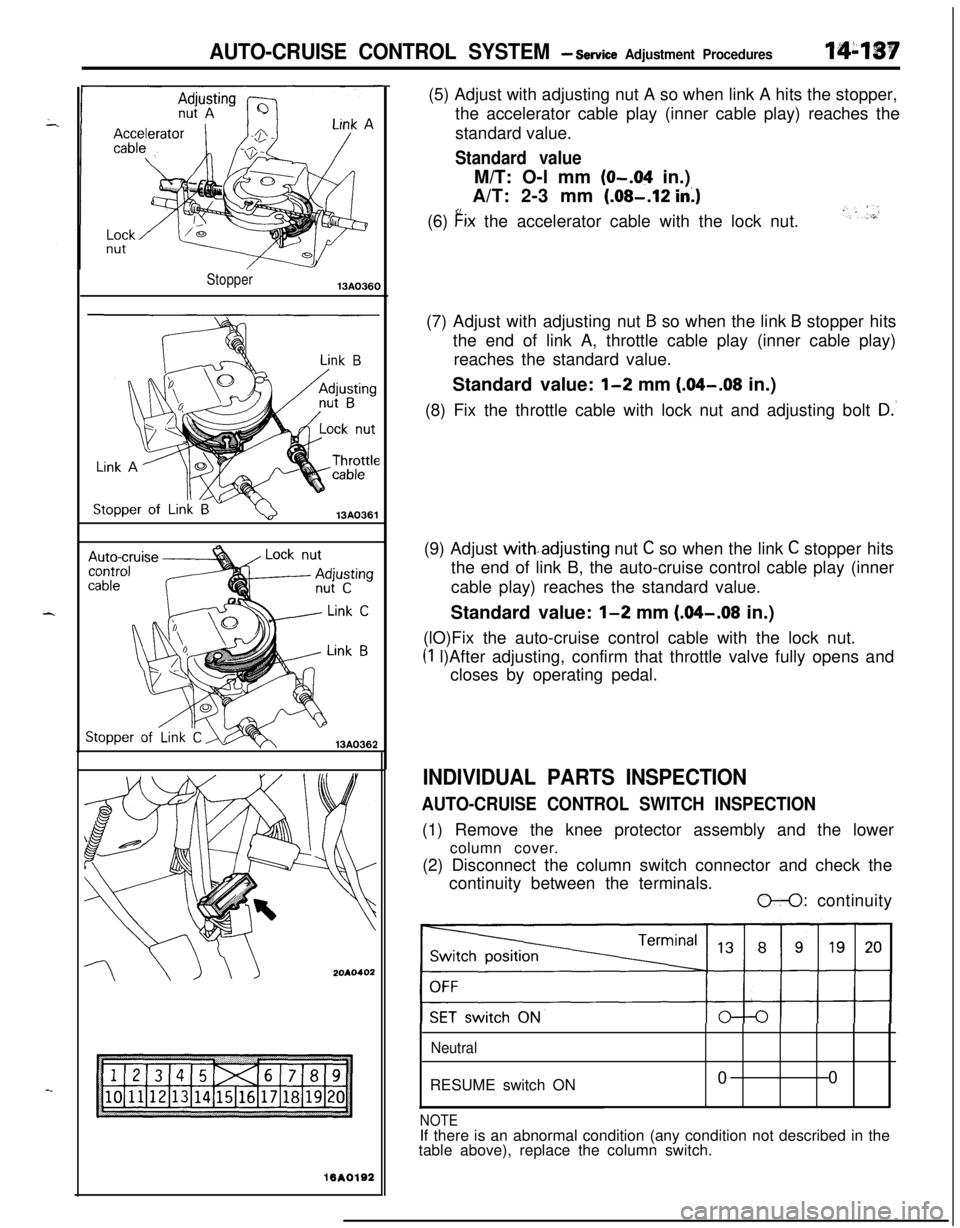
lBAOlS2(5) Adjust with adjusting nut A so when link A hits the stopper,
the accelerator cable play (inner cable play) reaches the
standard value.
Standard valueM/T: O-l mm
(O-.04 in.)
A/T: 2-3 mm (.08-.12
in.)(6)
Fix the accelerator cable with the lock nut.
(7) Adjust with adjusting nut
B so when the link B stopper hits
the end of link A, throttle cable play (inner cable play)
reaches the standard value.
Standard value:
l-2 mm (.04-.08 in.)
(8) Fix the throttle cable with lock nut and adjusting bolt
D.‘(9) Adjust with.adjusting nut
C so when the link C stopper hits
the end of link B, the auto-cruise control cable play (inner
cable play) reaches the standard value.
Standard value:
l-2 mm (.04-.08 in.)
(lO)Fix the auto-cruise control cable with the lock nut.
(1 l)After adjusting, confirm that throttle valve fully opens and
closes by operating pedal.
INDIVIDUAL PARTS INSPECTION
AUTO-CRUISE CONTROL SWITCH INSPECTION(1) Remove the knee protector assembly and the lower
column cover.
(2) Disconnect the column switch connector and check the
continuity between the terminals.
O-0: continuity
NeutralRESUME switch ON00
NOTEIf there is an abnormal condition (any condition not described in the
table above), replace the column switch.
Page 592 of 1216
14-138AUTO-CRUISE CONTROL SYSTEM - Service Adjustment Procedures
07A0051
07AOO50
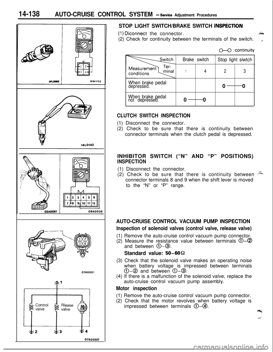
STOP LIGHT SWITCH/BRAKE SWITCH ItiSPECTlON
(1) Diconnect the connector.66(2) Check for continuity between the terminals of the switch.
_
When brake pedaldepressed.
When brake pedalnot depressed.
m :continuity
Brake switch
Stop light siwtch
142300
00
CLUTCH SWITCH INSPECTION(1) Disconnect the connector.
(2) Check to be sure that there is continuity between
connector terminals when the clutch pedal is depressed.
INHIBITOR SWITCH (“N” AND “P” POSITIONS)
INSPECTION(1) Disconnect the connector.
(2) Check to be sure that there is continuity between
Aconnector terminals 8 and 9 when the shift lever is moved
to the “N” or “P” range.
AUTO-CRUISE CONTROL VACUUM PUMP INSPECTION
Inspection of solenoid valves (control valve, release valve)(1) Remove the auto-cruise control vacuum pump connector.
(2) Measure the resistance value between terminals
0-0and between
0-0.
Standard value: 50-6OQ
(3) Check that the solenoid valve makes an operating noise
when battery voltage is impressed between terminals
0-0 and between 0-0.(4) If there is a malfunction of the solenoid valve, replace the
auto-cruise control vacuum pump assembly.
Motor inspection(1) Remove the auto-cruise control vacuum pump connector.
(2) Check that the motor revolves when battery voltage is
impressed between terminals @-@I.
@k
Page 593 of 1216
AUTO-CRUISE CONTROL SYSTEM - service Adjustment ~rocehre~
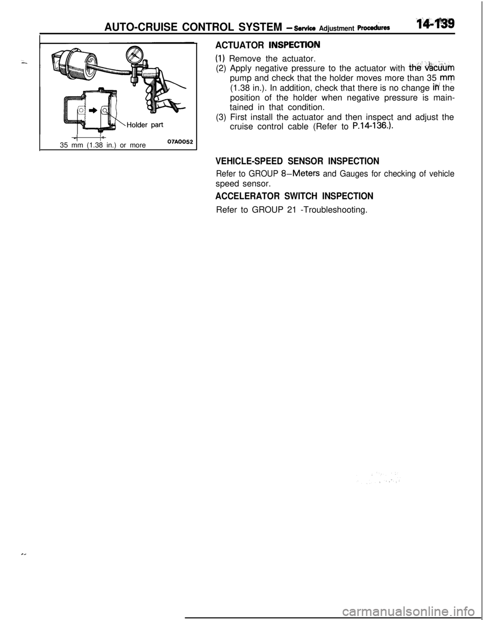
ACTUATOR INSPECTlCfN
(1) Remove the actuator.
(2) Apply negative pressure to the actuator with
the! &c&mpump and check that the holder moves more than 35
,mm(1.38 in.). In addition, check that there is no change
iii the
position of the holder when negative pressure is main-
tained in that condition.
(3) First install the actuator and then inspect and adjust the
cruise control cable (Refer to
P.14-136.).
I,_1I-35 mm (1.38 in.) or more07AOO52
VEHICLE-SPEED SENSOR INSPECTION
Refer to GROUP 8-Meters and Gauges for checking of vehiclespeed sensor.
ACCELERATOR SWITCH INSPECTIONRefer to GROUP 21 -Troubleshooting.
Page 594 of 1216
14-140AUTO-CRUISE ‘CONTROL SYSTEM - Auto-cruise Control
AUTO-CRUISE CONTROLN14TLL
REMOVAL AND INSTALLATION
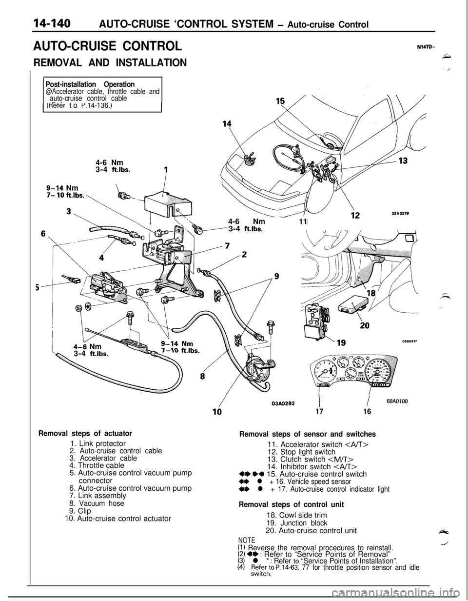
Post-installation Operation@Accelerator cable, throttle cable andauto-cruise control cableI- _1 (Keter to P.14-136.)4-6 Nm
3-4
ft:lbs.
9-14 Nm7- 10 ft.lbs. \
\ I- \ ‘.\-4-6 Nm - 11
3-4 ft.lbs.
4-6 Nmw3-4 ft.lbs.--Qc ‘”
Removal steps of actuator1. Link protector
2. Auto-cruise control cable
3. Accelerator cable4. Throttle cable
5. Auto-cruise control vacuum pump
connector
6. Auto-cruise control vacuum pump
7. Link assembly
8. Vacuum hose9. Clip
IO. Auto-cruise control actuator
/03AO28210II68AOlOO
1716
Removal steps of sensor and switches11. Accelerator switch
12. Stop light switch
13. Clutch switch
Removal steps of control unit18. Cowl side trim
19. Junction block20. Auto-cruise control unit
NOTE(1) Reverse the removal procedures to reinstall.(2) +* : Refer to “Service Points of Removal”(3) l * : Refer to “Service Points of Installation”.(4)%l;;to P. 14-63, 77 for throttle position sensor and idle
Page 595 of 1216
AUTO-CRUISE CONTROL SYSTEM - Auto-cruise Control14-141
SERVICE POINTS OF REMOVAL?trmNWpBC
15. REMOVAL OF AUTO-CRUISE CONTROL SWITCHRefer to GROUP
8-Column Switch.
16. REMOVAL OF VEHICLE SPEED SENSORRefer to GROUP
8-Meters and Gauges.
17. REMOVAL OF AUTO-CRUISE CONTROL INDICATOR
LIGHTRefer to GROUP
8-Meters and Gauges.
INSPECTIONN14lDCEl Check the inner and outer cable for damage.
l Check the cable for smooth movement.
l Check the link protector for damage.
CHECKING THE AUTO-CRUISE CONTROL ACTUATORRefer to
P.14-138.
SERVICE POINTS OF INSTALLATIONN14TDDDD
17. INSTALLATION OF AUTO-CRUISE CONTROL INDICA-
TOR LIGHTRefer to GROUP
8-Meters and Gauges.
16. INSTALLATION OF AUTO-CRUISE CONTROL SWITCHRefer to GROUP
8-Column Switch.
15. INSTALLATION OF VEHICLE SPEED SENSORRefer to GROUP
8-Meter and Gauges.
Page 898 of 1216
21-204AUTOMATIC TRANSAXLE - Troubleshooting
c;_----__---___-.
IGNITIONSWITCH(IG2)0
?
3E-7r
0
1UA
\IEjC-53mJ
ca (LB)
POWER/
ECONOMY
;$;;E OVER "r-
D-19A, .
12l!i3Fl3453$
,F
IGHT
3 19 ~lo~ll~l2~la~lq1qls
E
A/T SELECTOR
LEVER POSITION
ILLUMINATIONLIGHT
WITHOUTAU;iUi~;UISE
hf---
II
sP5 11
LIEI
AUTO-
CRUISE
CONTROL
UNIT
Y
-t
______--___---__--------
4
gF
C-61 57_______-__-----_---_-----
J/B
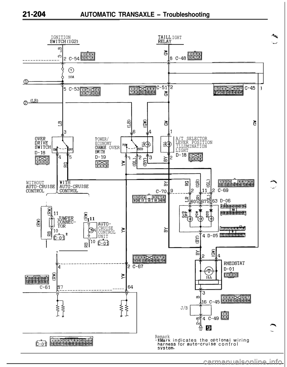
Remark**Mark indicates the oPtional wiringFEI~~I;S for auto-cruise control
Page 899 of 1216
AUTOMATIC TRANSAXLE - Troubleshooting21-205
AIR CONDITIONER
CONTROL UNITIGNI
CRCFILTER
B-11
ON+OFF:2700kP.%(384Psl)OFF+ON:
$;X;kERATOR
SWITCH
WITH
WITHOUT,$J;$JR~;UISE 1AUTO-CRUISE. CONTROL
SELFJ-DIAGNOSIS
CONNECTOR
TIO1
/-1. 8LENGINE
3J
I
IL.&.j IUK1
mB
x 1
mm
CLCL
--
‘----_06
Pz
1_----
t
29I
POWE
TRANSTOR
c-30
FRONT SIDE
p&a-q
E%ERSE
p!!iQqI-----
101
NON-TURBC
/ 0
2_----II
A
-----02
9
I.----,
IL-B
GtD G:DGB“tD----1
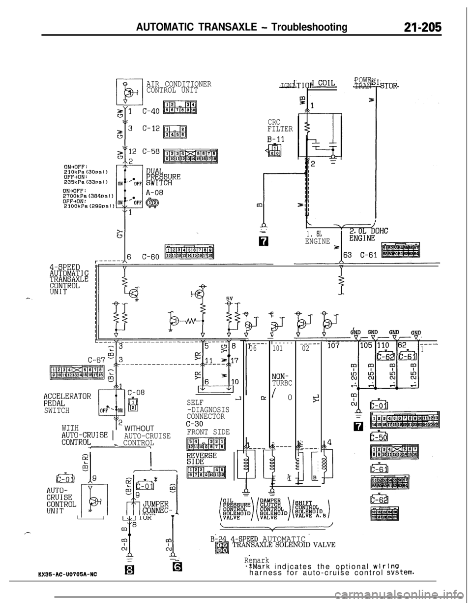
B-24 4-SPEED AUTOMATICTRANSAXLE SOLENOID VALVE
Remark*%Mark indicates the optional wlrlnsharness for auto-cruise control system.KX35-AC-U0705A-NCfg