fuse chart MITSUBISHI ECLIPSE 1991 Service Manual
[x] Cancel search | Manufacturer: MITSUBISHI, Model Year: 1991, Model line: ECLIPSE, Model: MITSUBISHI ECLIPSE 1991Pages: 1216, PDF Size: 67.42 MB
Page 150 of 1216

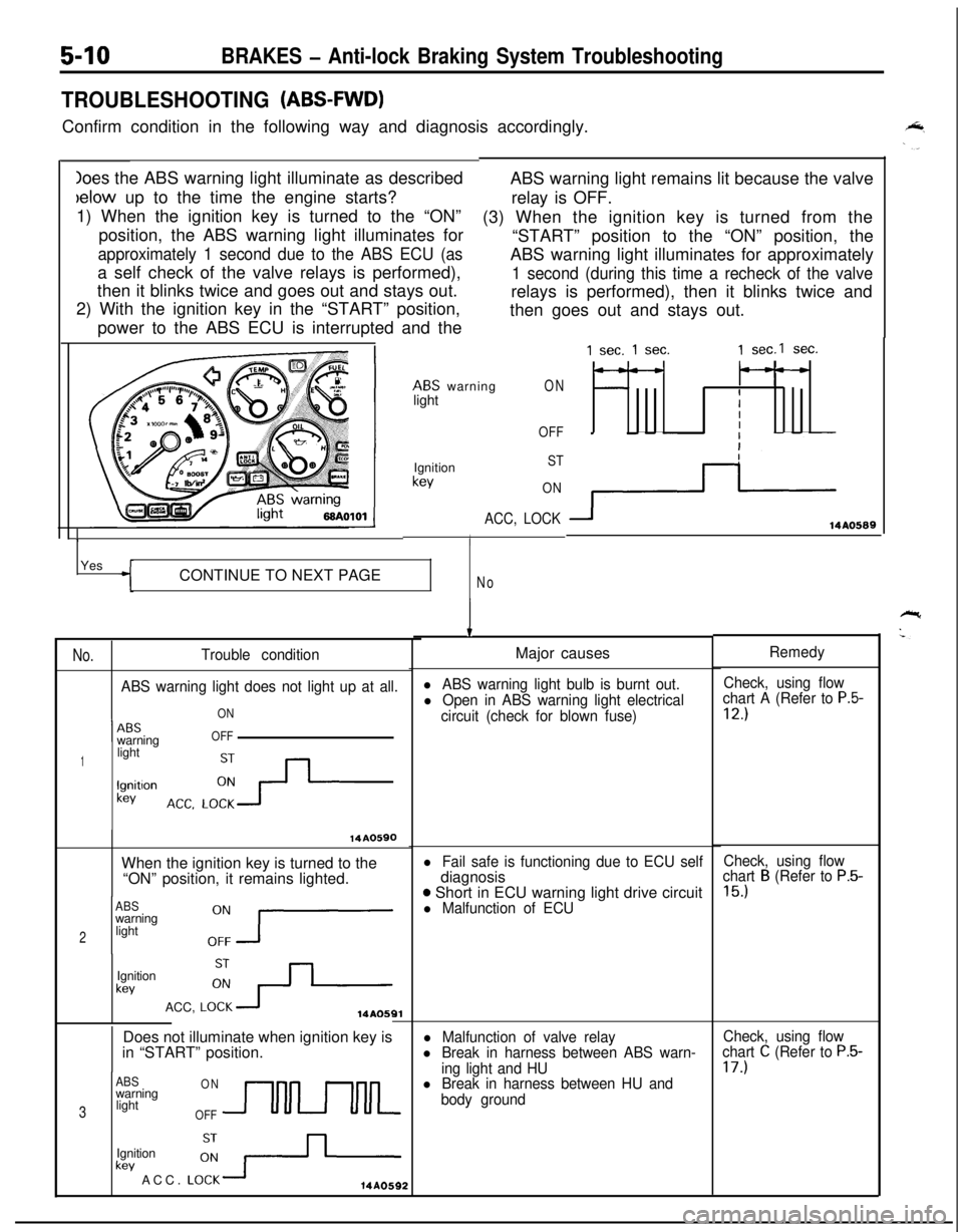
Ioes the ABS warning light illuminate as describedbelow up to the time the engine starts?
1) When the ignition key is turned to the “ON”
position, the ABS warning light illuminates for
approximately 1 second due to the ABS ECU (asa self check of the valve relays is performed),
then it blinks twice and goes out and stays out.
2) With the ignition key in the “START” position,
power to the ABS ECU is interrupted and the
5-10BRAKES - Anti-lock Braking System Troubleshooting
TROUBLESHOOTING (ABS-FWD)Confirm condition in the following way and diagnosis accordingly.
ABS warning light remains lit because the valve
relay is OFF.
(3) When the ignition key is turned from the
“START” position to the “ON” position, the
ABS warning light illuminates for approximately
1 second (during this time a recheck of the valverelays is performed), then it blinks twice and
then goes out and stays out.
ABS warning
lightON
OFF
1Ignition
kev
ST
ON
ACC, LOCK
IYes
CONTINUE TO NEXT PAGE
No
No.Trouble condition
ABS warning light does not light up at all.
ON
1 --ABSwarningOFF
1lightlgnitlon
kev
14A0590When the ignition key is turned to the
“ON” position, it remains lighted.
ABSwarning
2light
Ignition
kevACC,
LO:+14AOSQlDoes not illuminate when ignition key is
in “START” position.
ABSONwarning
3lightOFFUULkev ACC.
LO:-+-Ignition14A0592
1 sec. 1 sec.1 sec.1 sec.
---
IIII
3114AO589
IMajor causes
l ABS warning light bulb is burnt out.Check, using flow
l Open in ABS warning light electricalchart A (Refer to P.5-
circuit (check for blown fuse)12.)
l Fail safe is functioning due to ECU selfdiagnosis
o Short in ECU warning light drive circuitl Malfunction of ECU
l Malfunction of valve relayl Break in harness between ABS warn-
ing light and HU
l Break in harness between HU and
body groundRemedy
Check, using flow
chart
B (Refer to P.5-
15.)
Check, using flow
chart C (Refer to P.5-17.)
Page 165 of 1216

BRAKES - Anti-lock Braking System Troubleshooting5-25
TROUBLESHOOTING (ABS-AWD)Confirm condition in the following way and diagnosis accordingly.
C
F
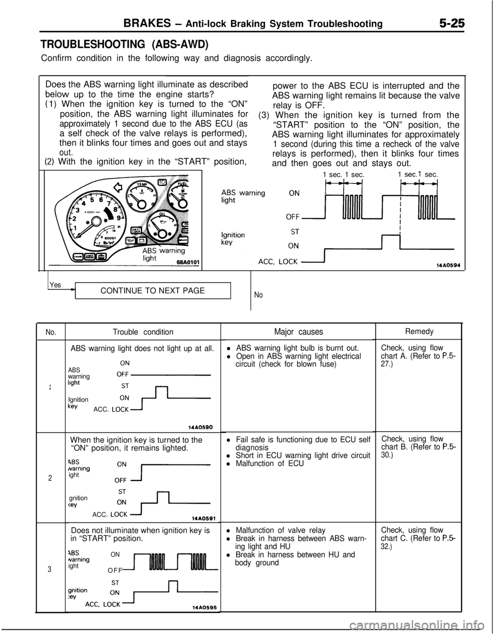
>oes the ABS warning light illuminate as described
relow up to the time the engine starts?
1) When the ignition key is turned to the “ON”
position, the ABS warning light illuminates for
approximately 1 second due to the ABS ECU (asa self check of the valve relays is performed),
then it blinks four times and goes out and stays
out.power to the ABS ECU is interrupted and the
ABS warning light remains lit because the valve
relay is OFF.
t:2) With the ignition key in the “START” position,(3) When the ignition key is turned from the
“START” position to the “ON” position, the
ABS warning light illuminates for approximately
1 second (during this time a recheck of the valverelays is performed), then it blinks four times
and then goes out and stays out.IO1
-1 sec. 1 sec.1
sec.1 sec.
14AO594
YesCONTINUE TO NEXT PAGE
No
No.
1
2
3
Trouble condition
ABS warning light does not light up at all.
ABSwarninglightOFFIgnitionkey
ACC.
LO;-+
14AOSSOWhen the ignition key is turned to the
“ON” position, it remains lighted.
4BSNamingight
0:7gnition
wACC.
LO:+14A0591Does not illuminate when ignition key is
in “START” position.
4BSNamingightONOFF
14A0595
Major causes
l ABS warning light bulb is burnt out.
l Open in ABS warning light electrical
circuit (check for blown fuse)
l Fail safe is functioning due to ECU self
diagnosis
l Short in ECU warning light drive circuitl Malfunction of ECU
l Malfunction of valve relay
l Break in harness between ABS warn-
ing light and HU
l Break in harness between HU and
body groundRemedy
Check, using flow
chart A. (Refer to
P.5-27.)
Check, using flow
chart B. (Refer to P.5-30.)
Check, using flow
chart C. (Refer to
P.5-
32.)
Page 568 of 1216

14-114AUTO-CRUISE CONTROL SYSTEM - Troubleshooting
CHECK CHART
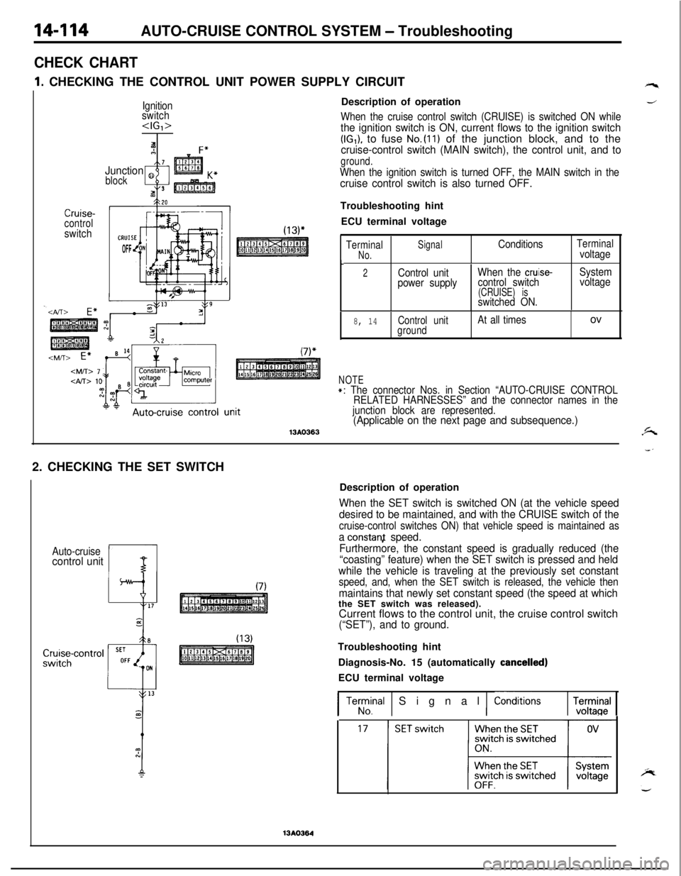
1I. CHECKING THE CONTROL UNIT POWER SUPPLY CIRCUIT
Ignition
switch
IAF”7Junction 8
block
tI3
Crurse-controlswitch
OFFDescription of operation
When the cruise control switch (CRUISE) is switched ON whilethe ignition switch is ON, current flows to the ignition switch(IG,), to fuse No.(ll) of the junction block, and to thecruise-control switch (MAIN switch), the control unit, and to
ground.When the ignition switch is turned OFF, the MAIN switch in thecruise control switch is also turned OFF.Troubleshooting hint
ECU terminal voltage
TerminalSignal
No.ConditionsTerminalvoltage
t2Control unitWhen the cruise-System
power supplycontrol switchvoltage
(CRUISE) isswitched ON.
8, 14Control unitAt all timesovground
NOTE+: The connector Nos. in Section “AUTO-CRUISE CONTROL
RELATED HARNESSES” and the connector names in the
junction block are represented.
(Applicable on the next page and subsequence.)13AO3632. CHECKING THE SET SWITCH
Auto-cruisecontrol unitDescription of operation
When the SET switch is switched ON (at the vehicle speed
desired to be maintained, and with the CRUISE switch of the
cruise-control switches ON) that vehicle speed is maintained as
a constanf speed.
Furthermore, the constant speed is gradually reduced (the
“coasting” feature) when the SET switch is pressed and held
while the vehicle is traveling at the previously set constant
speed, and, when the SET switch is released, the vehicle then
maintains that newly set constant speed (the speed at whichthe SET switch was released).
Current flows to the control unit, the cruise control switch
(“SET”), and to ground.Troubleshooting hint
Diagnosis-No. 15 (automatically
cancelled)ECU terminal voltage
1 Terrrnal 1 Signal 1 ConditionsrEl
13AO364
Page 1063 of 1216

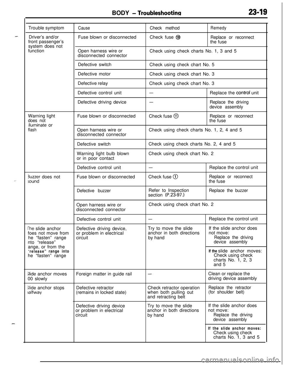
BODY - Troubleshootinn2349Trouble symptom
Driver’s and/or
front passenger’s
system does not
function
CauseFuse blown or disconnected
Open harness wire or
disconnected connectorCheck methodRemedyCheck fuse
@IReplace or reconnectthe fuse
Check using check charts No. 1, 3 and 5
Defective switch
Defective motor
Defective relay
Defective control unit
Defective driving deviceCheck using check chart No. 5
Check using check chart No. 3
Check using check chart No. 3
-Replace the control unit
-Replace the driving
device assemblyWarning light
does notlluminate or
flashFuse blown or disconnected
Open harness wire or
disconnected connectorCheck fuse
@IReplace or reconnectthe fuse
Check using check charts No. 1, 2, 4 and 5
Defective switch
Warning light bulb blown
or in poor contactCheck using check charts No. 2, 4 and 5
Check using check chart No. 2
3uzzer does notsoundDefective control unit
Fuse blown or disconnected
Defective buzzer
-Check fuse @
Refer to Inspection
section
(P.23-97.)Replace the control unit
Replace or reconnectthe fuse
Replace the buzzerOpen harness wire or
disconnected connectorCheck using check chart No. 2
Defective control unit
-Replace the control unit
The slide anchorDefective driving device,Try to move the slideIf the slide anchor does
foes not move fromor problem in electricalanchor in both directionsnot move:
he “fasten” rangecircuitby hand
Replace the drivingnto “release”device assemblyange, or from the
‘release”range intoIf the slide anchor moves:
he “fasten” rangeCheck using check
charts No. 1, 2, 3
and 5
Glide anchor moves
00 slowly
Slide anchor stopsralfwayForeign matter in guide rail
Defective retractor
(remains in locked state)
-Clean or replace the
driving device assembly
Check retractor operation
Replace the retractorwhen both pulling out(for shoulder belt)and retracting belt
Defective driving deviceTry to move the slide
or problem in electricalanchor in both directions
circuit
by handIf the slide anchor does
not move:
Replace the driving
device assemblyIf the slide anchor moves:
Check using check
charts No. 1, 3 and 5