Table MITSUBISHI ECLIPSE CROSS 2020 (in English) User Guide
[x] Cancel search | Manufacturer: MITSUBISHI, Model Year: 2020, Model line: ECLIPSE CROSS, Model: MITSUBISHI ECLIPSE CROSS 2020Pages: 427, PDF Size: 78.05 MB
Page 153 of 427
4-wheel drive operation 5-72 Features and controls
5
N00542501087
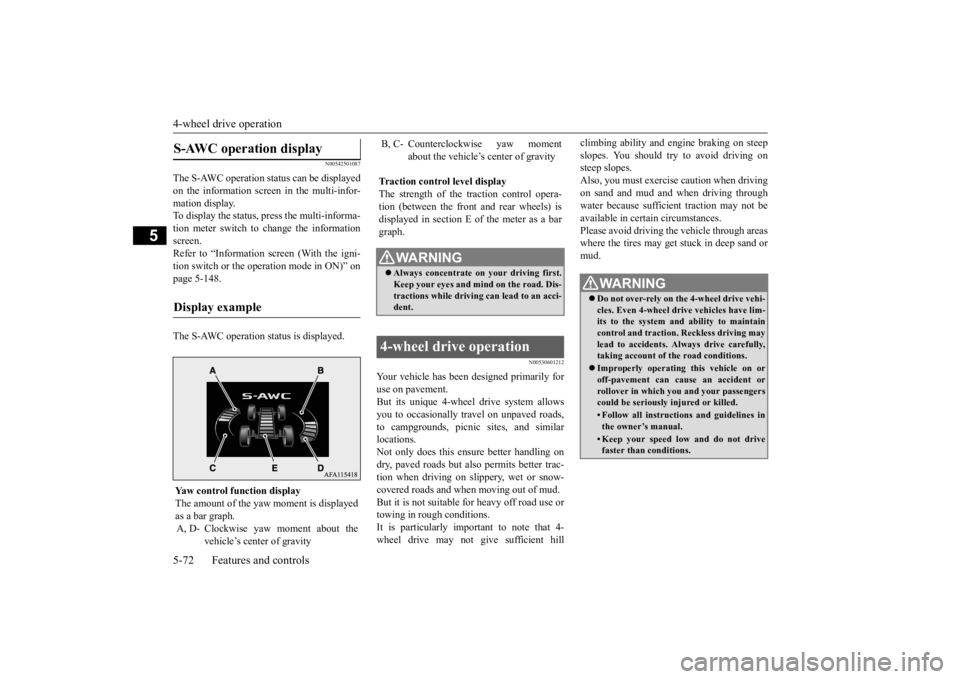
The S-AWC operation status can be displayed on the information screen in the multi-infor-mation display. To display the status, press the multi-informa- tion meter switch to change the informationscreen. Refer to “Information screen (With the igni- tion switch or the operation mode in ON)” onpage 5-148. The S-AWC operation status is displayed.
N00530601212
Your vehicle has been designed primarily for use on pavement. But its unique 4-wheel drive system allowsyou to occasionally travel on unpaved roads, to campgrounds, picnic sites, and similar locations.Not only does this ensure better handling on dry, paved roads but also permits better trac- tion when driving on slippery, wet or snow-covered roads and when moving out of mud. But it is not suitable for heavy off road use or towing in rough conditions.It is particularly important to note that 4- wheel drive may not give sufficient hill
climbing ability and engine braking on steep slopes. You should try to avoid driving on steep slopes. Also, you must exercise caution when drivingon sand and mud and when driving through water because sufficient traction may not be available in certain circumstances.Please avoid driving the vehicle through areas where the tires may get stuck in deep sand or mud.
S-AWC operation display
Display example
Yaw control function displayThe amount of the yaw
moment is displayed
as a bar graph. A, D- Clockwise yaw moment about the
vehicle’s center of gravity
B, C- Counterclockwise yaw moment
about the vehicle’s center of gravity
Traction control level display The strength of the traction control opera-tion (between the front and rear wheels) is displayed in section E of the meter as a bar graph.
WA R N I N G Always concentrate on your driving first. Keep your eyes and mi
nd on the road. Dis-
tractions while driving can lead to an acci- dent.
4-wheel drive operation
WA R N I N G Do not over-rely on the 4-wheel drive vehi- cles. Even 4-wheel drive vehicles have lim-its to the system and ability to maintain control and traction. Reckless driving may lead to accidents. Always drive carefully,taking account of the road conditions. Improperly operating this vehicle on or off-pavement can cause an accident or rollover in which you and your passengers could be seriously injured or killed.• Follow all instructions and guidelines inthe owner’s manual.• Keep your speed low and do not drivefaster than conditions.
BK0277700US.bo
ok 72 ページ 2019年3月8日 金曜日 午前9時23分
Page 156 of 427
Cautions on the handling of 4-wheel drive vehicles
Features and controls 5-75
5
Carefully wash the vehicle with water. Drive the vehicle slowly while lightly depressing the brake pedal in order to dry out the brakes. If the brakes still do notfunction properly, co
ntact an authorized
Mitsubishi Motors dealer or a repair facil- ity of your choice as soon as possible tohave the brakes checked. Remove the insects, dried grass, etc. clog- ging the radiator core. After driving through water, check the engine, transaxle and differential oil. If the oil or grease is milky or cloudy because of water contamination, it mustbe replaced with new oil. Check the inside of the vehicle. If water entry is found, dry the carpet etc. Inspect the headlights. If water is in the headlight housing, have it drained at an authorized Mitsubishi Motors dealer or arepair facility of your choice.
N00530801230
Since the driving torque can be applied to thefour wheels, the driving performance of the
vehicle when operating in 4-wheel drive is greatly affected by the condition of the tires. Pay close attention to the tires. Install only the specified tires on all wheels. Refer to “Tires and wheels” on page 11-7. Be sure all four tires and wheels are the same size and type. When it is necessary to replace any of thetires or wheels, replace all four. All tires should be rotated before the wear difference between the front and rear tires is recognizable.
Good vehicle performance cannot be expected if there is a difference in wear between tires. Refer to “Tire rotation” on page 9-17. Check the tire inflation pressure regularly.
Cautions on the handling of 4-wheel drive vehicles Tires and wheels
CAUTION Always use tires of the same size, type, and brand that have no wear differences. Using tires of different size, type, brands or degree of wear, will increase the differential oil tem- perature and result in possible damage to thedriving system. Further, the drive train will be subject to excessive loading, possibly leading to oil leakage, component seizure, orother serious failures.
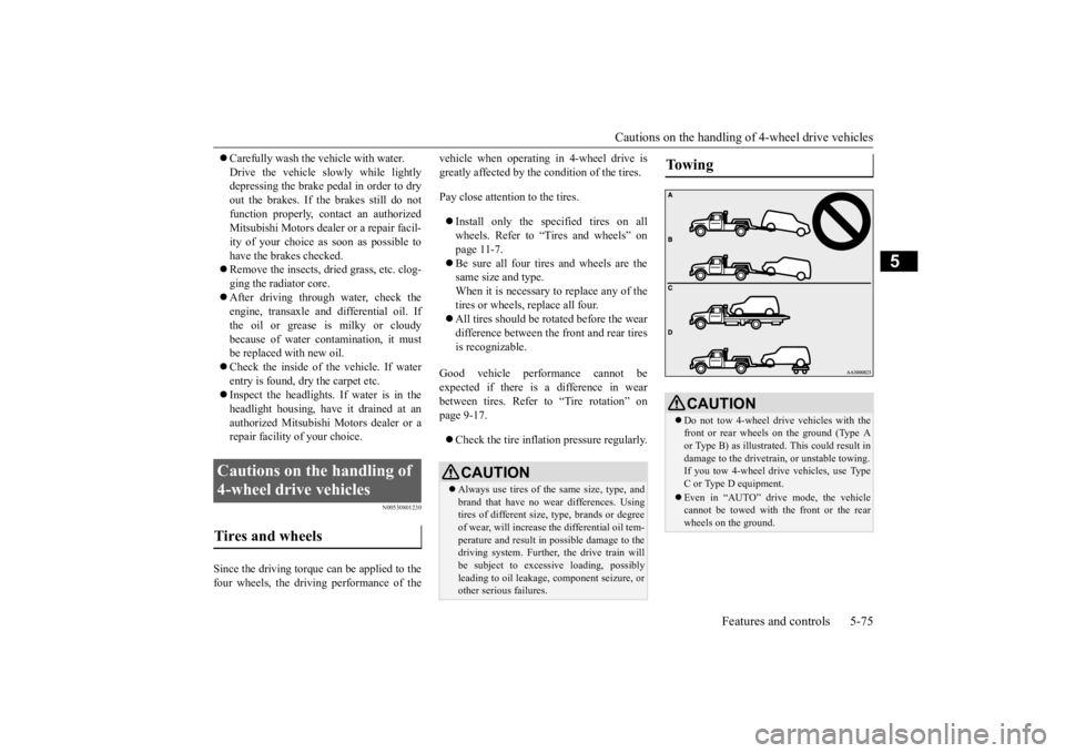
To w i n g
CAUTION Do not tow 4-wheel drive vehicles with the front or rear wheels on the ground (Type Aor Type B) as illustrated. This could result in damage to the drivetra
in, or unstable towing.
If you tow 4-wheel dr
ive vehicles, use Type
C or Type D equipment. Even in “AUTO” drive mode, the vehicle cannot be towed with the front or the rear wheels on the ground.
BK0277700US.bo
ok 75 ページ 2019年3月8日 金曜日 午前9時23分
Page 159 of 427
Brake auto hold (if so equipped) 5-78 Features and controls
5
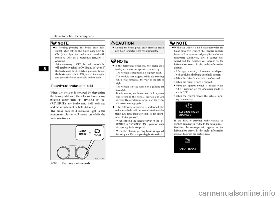
When the vehicle is stopped by depressing the brake pedal with the selector lever in anyposition other than “P” (PARK) or “R” (REVERSE), the brake auto hold activates and the vehicle will be held stationary.The brake auto hold indicator light in the instrument cluster will come on while the system activates. If keeping pressing the brake auto hold switch after setting the brake auto hold to ON (stand by), the brake auto hold will return to OFF as a protection function is operated.After returning to OFF, the brake auto hold will not be switched to ON (Stand by) even if the brake auto hold switch is pressed. To setthe brake auto hold to ON, restart the engine and press the brake auto
hold switch again.
To activate brake auto hold
NOTE
or
CAUTIONRelease the brake pedal only after the brake auto hold indicator light has illuminated.NOTE
In the following situations, the brake auto hold system may not operate temporarily. • The vehicle is stopped on a slippery road. • The vehicle was stopped while the steering wheel was turned all the way to the left or right. • The vehicle is being turned on a parking lot turntable. If this occurs, the brake auto hold systemwill return to the normal operation if you depress the accelerator pedal and the vehi- cle starts moving again.
If the following operation is performed, the brake auto hold will be deactivated and thebrake auto hold indicator light in the instru- ment cluster goes off. • When shifting the selector lever to the “P” (PARK) or “R” (REVERSE) position with depressing the brake pedal. • When the Electric parking brake is applied by using the Electric parking brake switch.
While the vehicle is held stationary with the brake auto hold system, the Electric parking brake will be automatically applied under the following conditions, and a buzzer will sound and the message will appear on theinformation screen in the multi-information display. • After approximately 10 minutes has elapsed with applying the brake auto hold system. • When the driver’s seat belt is unfastened. • When the driver’s door is opened.• When the ignition switch is turned to the “OFF” position or the operation mode isput in OFF. • When the system detects the vehicle mov- ing down a slope. If the Electric parking brake cannot be applied automatically due to the system mal-function, the message
will appear on the
information screen in the multi-information display. Depress the brake pedal.NOTE
BK0277700US.bo
ok 78 ページ 2019年3月8日 金曜日 午前9時23分
Page 164 of 427
Anti-lock braking system
Features and controls 5-83
5
N00531701715
Avoid hard braking and high-speed driv-
ing. Stop the vehicle in a safe place.
Test the system by restarting the engine
and driving at a speed of approximately
12 mph (20 km/h) or higher.
If the warning light/display then remains
off during driving, there is no abnormal
condition.
However, if the warning light/display do
not disappear, or if they come on again
when the vehicle is driven, have the vehi-
cle checked by an authorized Mitsubishi
Motors dealer or repair facility of your
choice as soon as possible. Warning light
or
Warning display
The anti-lock braking system and brake force
distribution function may not work, so hard
braking could make the vehicle unstable.
Avoid hard braking and high-speed driving.
Stop the vehicle in a safe place and contact an
authorized Mitsubishi Motors dealer or repair
facility of your choice.
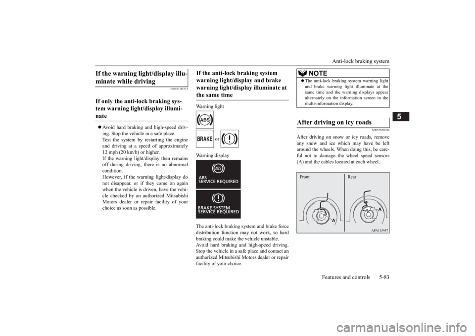
N00529201104
After driving on snow or icy roads, remove
any snow and ice which may have be left
around the wheels. When doing this, be care-
ful not to damage the wheel speed sensors
(A) and the cables located at each wheel.
If the warning light/display illu-
minate while driving If only the anti-lock braking sys-
tem warning light/display illumi-
nate
If the anti-lock braking system
warning light/display and brake
warning light/display illuminate at
the same time
NOTE
The anti-lock braking system warning light
and brake warning light illuminate at the
same time and the warning displays appear
alternately on the information screen in the
multi-information display.After driving on icy roads Front Rear
BK0277700US.book 83 ページ 2019年3月12日 火曜日 午前9時34分
Page 206 of 427
Lane Departure Warning (LDW) (if so equipped)
Features and controls 5-125
5
N00578100058
If a problem occurs with the system, a visual warning specific to the type of the problem isgiven together with an audible alarm.
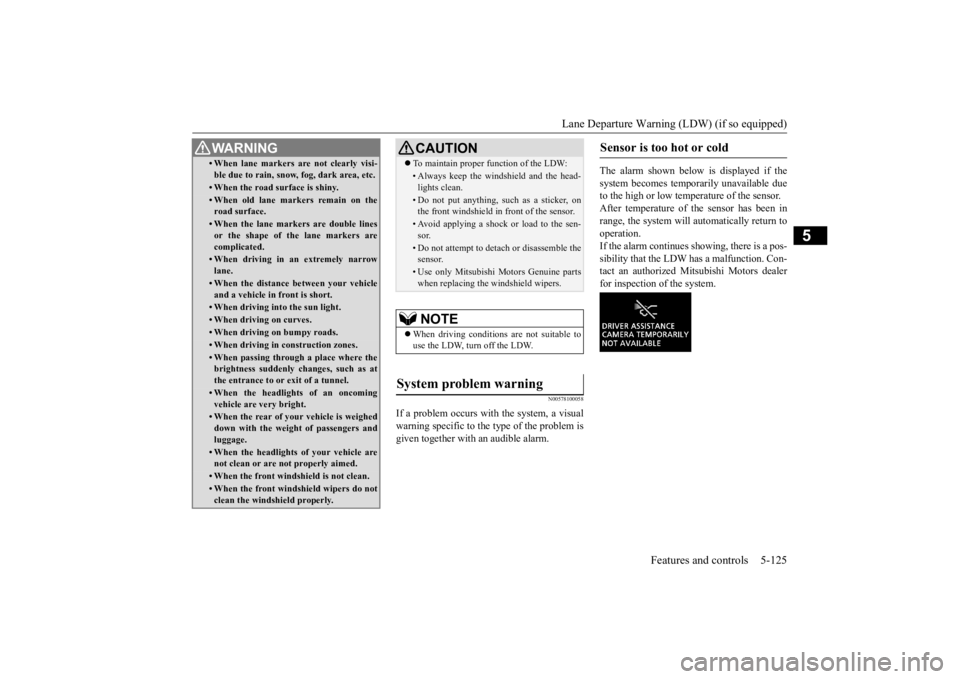
The alarm shown below is displayed if the system becomes temporarily unavailable due to the high or low temperature of the sensor.After temperature of the sensor has been in range, the system will automatically return to operation.If the alarm continues showing, there is a pos- sibility that the LDW has a malfunction. Con- tact an authorized Mitsubishi Motors dealerfor inspection of the system.
• When lane markers are not clearly visi- ble due to rain, snow, fog, dark area, etc.• When the road surface is shiny.• When old lane markers remain on theroad surface.• When the lane markers are double linesor the shape of the lane markers are complicated.• When driving in an extremely narrowlane.• When the distance between your vehicleand a vehicle in front is short.• When driving into the sun light.• When driving on curves.• When driving on bumpy roads.• When driving in construction zones.• When passing through a place where the brightness suddenly changes, such as at the entrance to or exit of a tunnel.• When the headlights of an oncomingvehicle are very bright. • When the rear of your vehicle is weigheddown with the weight of passengers andluggage.• When the headlights of your vehicle arenot clean or are not properly aimed.• When the front windshield is not clean.• When the front windshield wipers do notclean the windshield properly.WA R N I N G
CAUTION To maintain proper function of the LDW:• Always keep the windshield and the head- lights clean.• Do not put anything, such as a sticker, onthe front windshield in front of the sensor.• Avoid applying a shock or load to the sen-sor.• Do not attempt to detach or disassemble thesensor.• Use only Mitsubishi Motors Genuine partswhen replacing the windshield wipers.NOTE
When driving conditions are not suitable to use the LDW, turn off the LDW.
System problem warning
Sensor is too hot or cold
BK0277700US.book
125 ページ 2019年3月8日 金曜日 午前9時23分
Page 266 of 427
Warning lights
Features and controls 5-185
5
N00520501856
This indicator is a part
of the onboard diag-
nostic (OBD) system which monitors the emissions, engine control system or continu-ously variable transmission (CVT) control system. If a problem is detected in one of these systems, this indicator illuminates orflashes. When the igniti
on switch is turned to
the “ON” position or the operation mode is put in ON, this indicator normally comes onand goes off after the engine has started. This indicator will come on if the fuel tank filler cap is not properly tightened. If this
indicator comes on and stays on after refuel- ing, stop the engine and check that the cap is properly tightened. (Turn the cap clockwise until you hear clicking sounds.)If this indicator does not go off after several seconds or lights up while driving, have the system checked as soon as possible at anauthorized Mitsubishi Motors dealer or a repair facility of your choice.
CAUTION When the warning light remains on or does not come on, there is the possibility that the parking brake cannot be operated or released. Immediately contact the nearest authorized Mitsubishi Motors dealer. Whenthe warning light comes on during driving, immediately stop the vehicle in a safe place, and contact an authorized Mitsubishi Motorsdealer. If you inevitably have to park, park the vehicle on level and stable ground, shift the selector lever in “P” (PARK) positionand place chocks or blocks.
Engine malfunction indicator (“SERVICE ENGINE SOON” or “Check engine light”)
CAUTION Driving for a long time with the engine mal- function indicator on may cause more dam- age to the emission control system. This could also affect fuel economy and drivabil-ity. If this indicator does not come on when the ignition switch is turned to the “ON” posi- tion or the operation mode is put in ON, have the system checked at an authorizedMitsubishi Motors dealer or a repair facility of your choice.
If the engine malfunction indicator comes on while the engine is running, avoid driving at high speeds. During vehicle operation with the indicator on, the vehicle may not accelerate when youdepress the accelerator pedal. When the vehicle is stationary with the indi- cator on, you must depress the brake pedalmore firmly than usual since the engine idling speed is higher than usual and a vehi- cle with continuously variable transmission(CVT) has a stronger tendency to creep for- ward.NOTE
Do not disconnect the battery cable when the engine malfunction indicator (“SERVICEENGINE SOON” or “Check engine light”) is on. The engine electronic control module storescritical OBD information (especially exhaust emission data), which may be lost if the bat- tery cable is disconnected while the enginemalfunction indicator is on. This will make it difficult to diagnose the cause of future prob- lems.CAUTION
BK0277700US.book
185 ページ 2019年3月8日 金曜日 午前9時23分
Page 291 of 427
Sun visors 5-210 Features and controls
5
4. To remove the USB connector cable, turn the ignition switch to the “OFF” position or put the operation mode in OFF first and perform the installation steps in reverse.
N00566901274
1. Park your vehicle in a safe place and turnthe ignition switch to the “OFF” position or put the operation mode in OFF. 2. Connect the connector cable to the iPod. 3. Connect the connector cable to the USB input terminal. 4. To remove the connector cable, turn the ignition switch to the “OFF” position orput the operation mode in OFF first and perform the installation steps in reverse.
N00567001126
For details, please refer to the separatedowner’s manual for “Smartphone Link Dis- play Audio” or the “DISPLAY AUDIO”.
N00524601419
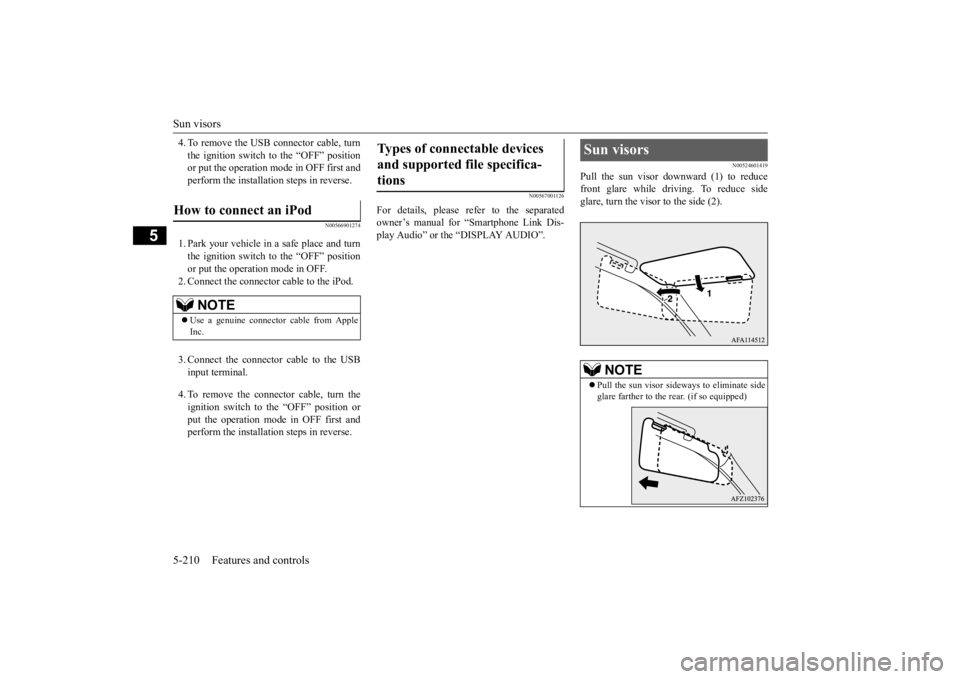
Pull the sun visor downward (1) to reducefront glare while driving. To reduce sideglare, turn the visor to the side (2).
How to connect an iPod
NOTE
Use a genuine connector cable from Apple Inc.
Types of connectable devices and supported file specifica- tions
Sun visors
NOTE
Pull the sun visor sideways to eliminate side glare farther to the rear. (if so equipped)
BK0277700US.book
210 ページ 2019年3月8日 金曜日 午前9時23分
Page 318 of 427
Loading information Driving safety 6-9
6
NOTE
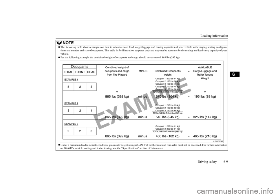
The following table shows examples on how to calculate total lo
ad, cargo/luggage and towing capaciti
es of your vehicle with var
ying seating configura-
tions and number and size of occupants. This
table is for illustration purposes only
and may not be accurate for the seating an
d load carry capacity of your
vehicle. For the following example the combined weight of
occupants and cargo should never exceed 865 lbs (392 kg).
Under a maximum loaded vehicle condition, gross axle weight rati
ngs (GAWR’s) for the front and r
ear axles must not be exceeded.
For further information
on GAWR’s, vehicle loading and trailer towing,
see the “Specifications” section of this manual.
BK0277700US.bo
ok 9 ページ 2019年3月8日 金曜日 午前9時23分
Page 322 of 427
Trailer towing
Driving safety 6-13
6
A safety chain must always be used between the towing vehicle and the trailer. Leave suf- ficient slack in the chain for turns. The chain should cross under the trailer tongue to pre-vent the tongue from dropping to the ground in case it becomes damaged or separated. For correct safety chain procedures, consultyour authorized Mitsubishi Motors dealer.
Your vehicle will need service more often when you’re towing a trailer. Refer to “WAR- RANTY AND MAINTENANCE MAN- UAL”. Especially important in traileroperation are automatic transaxle fluid, engine oil, rear axle oil, belt, cooling system and brake system. Each of these is covered inthis manual.For details, please refer to the “Vehicle care and maintenance” section. Check periodically to see that all hitch nutsand bolts are tight. Mitsubishi Motors recommends that any trailer having a total weight of 1,250 lb (567 kg) or more be equipped with its own electric or surge-type brakes. If you choose electric brakes, be sure they are electrically actuated. Do not attempt to tap into your vehicle’s hydraulic system. No mat- ter how successful it may seem, any attemptto attach trailer brakes to your vehicle’s hydraulic system will lower braking effec- tiveness and create a potential hazard.
Trailer lights and equipment must comply with federal, state, and local regulations.Check with your local recreational vehicle dealer for the requirements in your area, and use only equipment designed for your vehi-cle. Since lighting and wiring vary by trailer type and brand, you should have a qualified tech- nician install a suitable connector between the vehicle and the trailer. Improper equipment orinstallation can cause damage to your vehi- cle’s electrical system and affect your vehicle warranty. Many states and Canadian provinces require special outside mirrors when towing a trailer.Even if not required, you should install spe- cial mirrors if you cannot clearly see behind you, or if the trailer creates a blind spot. Ask your trailer sales or rental agency if any other items are recommended or required for your towing situation.
NOTE
Mitsubishi Motors recommends that sway control be used when
ever you are towing, to
improve towing stability. For further information, please contact your authorized Mitsubishi Motors dealer.
Safety chains
CAUTION Never tow a trailer without using a safety chain securely attached to both the trailer and the vehicle. If the coupling unit or hitch ball experiences a problem, the trailer may separate from your vehicle.
Maintenance when trailer tow- ing Trailer brakes
Trailer lights Additional trailer equipment
BK0277700US.bo
ok 13 ページ 2019年3月8日 金曜日 午前9時23分
Page 354 of 427
Jump-starting the engine For emergencies 8-3
8
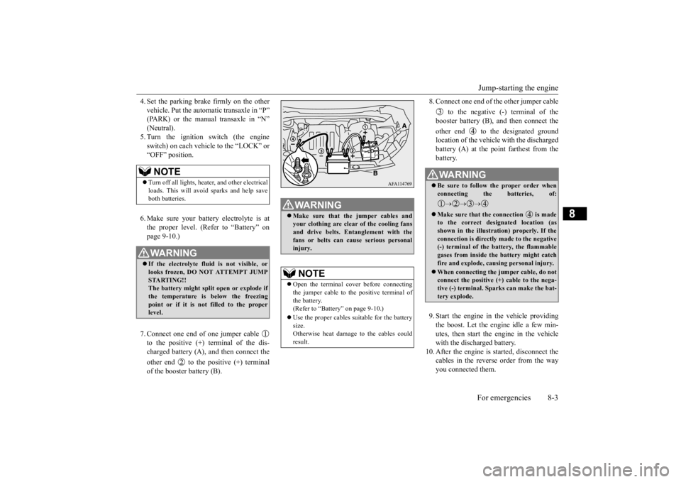
4. Set the parking brake firmly on the other vehicle. Put the automatic transaxle in “P” (PARK) or the manual transaxle in “N” (Neutral).5. Turn the ignition switch (the engine switch) on each vehicle to the “LOCK” or “OFF” position. 6. Make sure your battery electrolyte is at the proper level. (Refer to “Battery” on page 9-10.) 7. Connect one end of one jumper cable to the positive (+) terminal of the dis- charged battery (A), and then connect the other end to the positive (+) terminal of the booster battery (B).
8. Connect one end of the other jumper cable
to the negative (-) terminal of the booster battery (B), and then connect the other end to the designated ground location of the vehicle with the discharged battery (A) at the point farthest from thebattery. 9. Start the engine in the vehicle providing the boost. Let the engine idle a few min- utes, then start the engine in the vehicle with the discharged battery.
10. After the engine is started, disconnect the
cables in the reverse order from the way you connected them.
NOTE
Turn off all lights, heater, and other electrical loads. This will avoid sparks and help save both batteries.WA R N I N G If the electrolyte fluid is not visible, or looks frozen, DO NOT ATTEMPT JUMP STARTING!! The battery might split open or explode ifthe temperature is below the freezing point or if it is not filled to the proper level.
WA R N I N G Make sure that the jumper cables and your clothing are clear of the cooling fans and drive belts. Entanglement with the fans or belts can cause serious personalinjury.NOTE
Open the terminal cover before connecting the jumper cable to the positive terminal ofthe battery. (Refer to “Battery” on page 9-10.) Use the proper cables suitable for the battery size. Otherwise heat damage to the cables couldresult.
WA R N I N G Be sure to follow the proper order when connecting the batteries, of:
Make sure that the connection is made to the correct designated location (as shown in the illustration) properly. If the connection is directly made to the negative(-) terminal of the battery, the flammable gases from inside the battery might catch fire and explode, causing personal injury. When connecting the jumper cable, do not connect the positive (+) cable to the nega-tive (-) terminal. Sparks can make the bat- tery explode.
BK0277700US.bo
ok 3 ページ 2019年3月8日 金曜日 午前9時23分