Abs sensor MITSUBISHI ENDEAVOR 2004 Service Repair Manual
[x] Cancel search | Manufacturer: MITSUBISHI, Model Year: 2004, Model line: ENDEAVOR, Model: MITSUBISHI ENDEAVOR 2004Pages: 3870, PDF Size: 98.47 MB
Page 1 of 3870
2004 BRAKES
Anti-Lock Braking System (ABS) - Endeavor
GENERAL DESCRIPTION FEATURES The 4ABS ensures directional stability and control during hard braking.
This ABS uses a 4-sensor 4-channel system that controls all four wheels
independently of each other. The basic system is the same as that for the Lancer.
EBD (Electronic Brake-force Distribution system) control has been installed to
provide the ideal braking force for the rear wheels.
EBD CONTROL In ABS, electronic control is used so the rear wheel brake hydraulic pressure during
braking is regulated by rear wheel control solenoid valves in accordance with the
vehicle's rate of deceleration. The front and rear wheel slippages are calculated from
the signals received from the various wheel sensors. EBD control is a control
system which provides a high level of control for both vehicle braking force and
vehicle stability. The system has the following features:
To shorten the harness wires and enhance data transmission reliability,
communication with other ECU is performed over a CAN (Controller Area
Network). Fail-safe function ensures that safety is maintained. Diagnostic function provides improved serviceability. Because the system provides the optimum rear wheel braking force regardless
of vehicle load and the condition of the road surface, the system reduces the
required pedal depression force, particularly when the vehicle is heavily
loaded. Because the duty placed on the front brakes is reduced, the increases in pad
temperature can be controlled during front brake application to improve pad
wear.
2004 Mitsubishi Endeavor LS
2004 BRAKES Anti-Lock Braking System (ABS) - Endeavor
2004 Mitsubishi Endeavor LS
2004 BRAKES Anti-Lock Braking System (ABS) - Endeavor
Page 19 of 3870
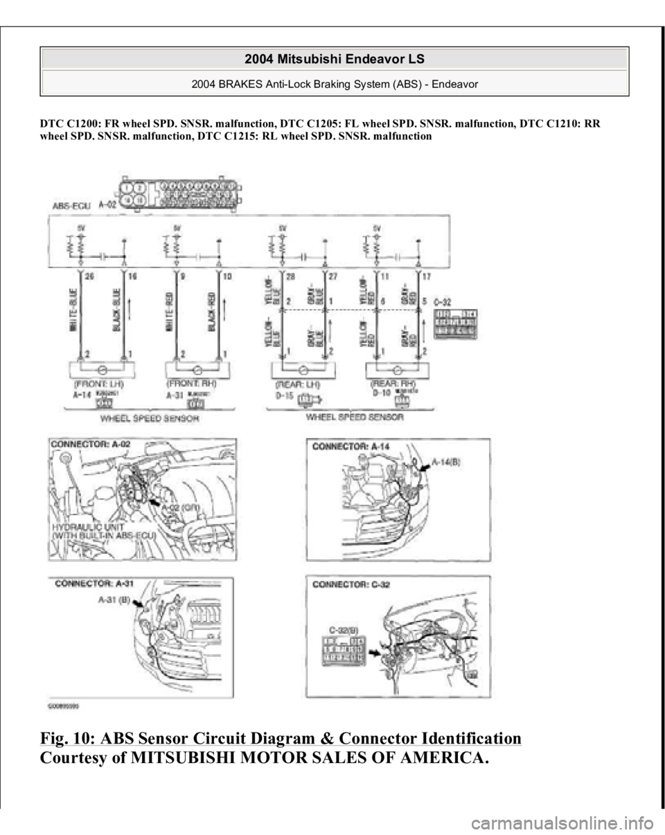
DTC C1200: FR wheel SPD. SNSR. malfunction, DTC C1205: FL wheel SPD. SNSR. malfunction, DTC C1210: RR
wheel SPD. SNSR. malfunction, DTC C1215: RL wheel SPD. SNSR. malfunction Fig. 10: ABS Sensor Circuit Diagram & Connector Identification
Courtes
y of MITSUBISHI MOTOR SALES OF AMERICA
.
2004 Mitsubishi Endeavor LS
2004 BRAKES Anti-Lock Braking System (ABS) - Endeavor
Page 20 of 3870
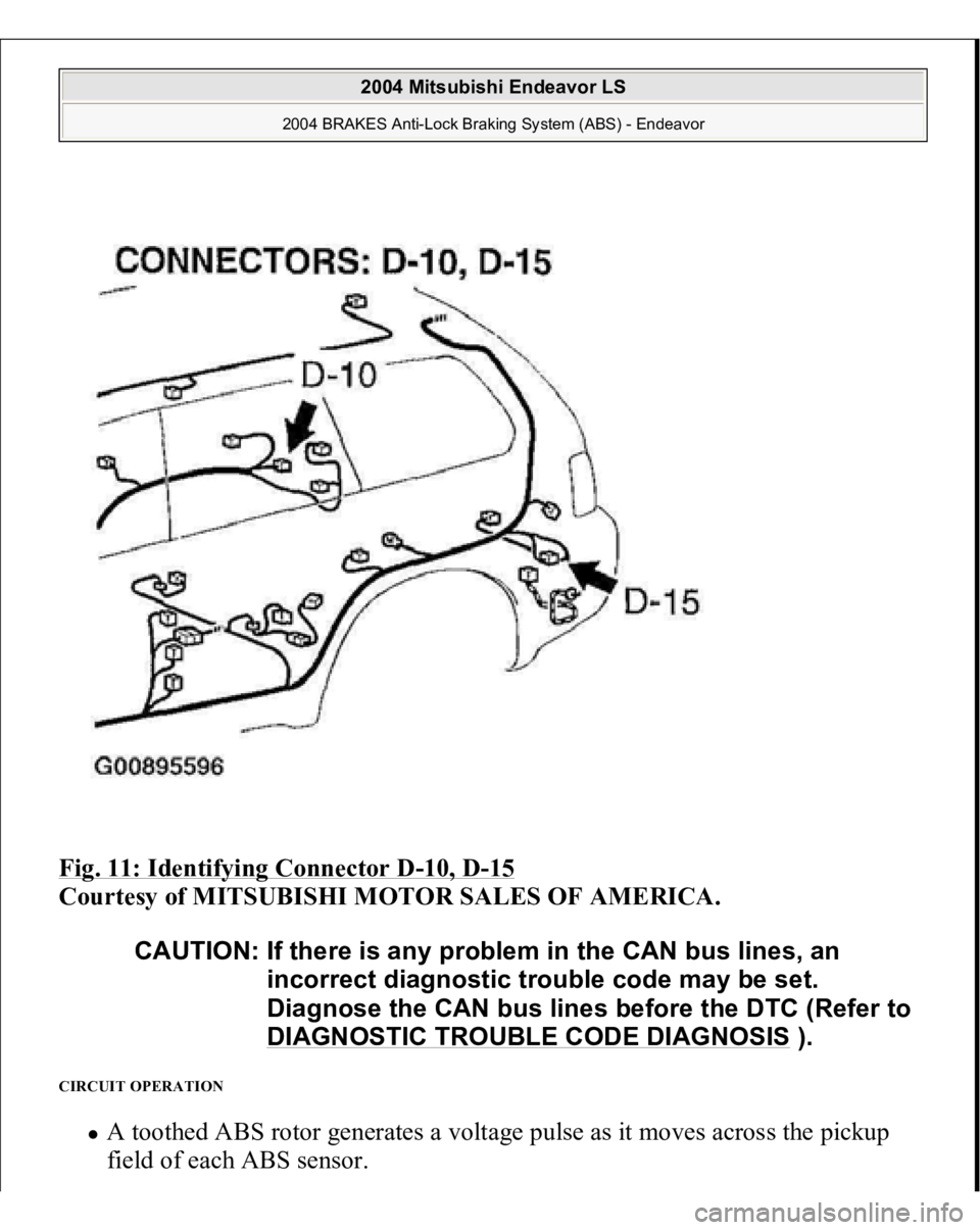
Fig. 11: Identifying Connector D
-10, D
-15
Courtesy of MITSUBISHI MOTOR SALES OF AMERICA.
CIRCUIT OPERATION
A toothed ABS rotor generates a voltage pulse as it moves across the pickup
field of each ABS sensor.
CAUTION: If there is any problem in the CAN bus lines, an
incorrect diagnostic trouble code may be set.
Diagnose the CAN bus lines before the DTC (Refer to
DIAGNOSTIC TROUBLE CODE DIAGNOSIS
).
2004 Mitsubishi Endeavor LS
2004 BRAKES Anti-Lock Braking System (ABS) - Endeavor
Page 21 of 3870
The amount of voltage generated at each wheel is determined by the clearance
between the ABS rotor teeth and the ABS sensor, and by the speed of rotation. Sends alternating current signals at frequencies which are proportional to the
rotation speeds of each wheel to the ABS electronic control unit (ABS-ECU). The ABS hydraulic unit modulates the amount of braking force individually
applied to each wheel cylinder.
ABS DTC SET CONDITIONS The ABS-ECU monitors voltage fluctuation in each ABS sensor circuit. If the ECU
detects short or open circuit in the circuit, it will set a diagnostic trouble code. TROUBLESHOOTING HINTS (THE MOST LIKELY CAUSES FOR THESE DTCS ARE TO SET ARE:)
Current trouble
Malfunction of the ABS sensor Damaged wiring harness or connector Malfunction of the hydraulic unit (integrated with ABS-ECU)
Past trouble
Carry out diagnosis with particular emphasis o connector(s) or wiring harness
in ABS sensor circuit. For diagnosis procedures, refer to HOW TO USE TROUBLESHOOTING/ INSPECTION SERVIC
).
DIAGNOSIS Required Special Tools:
MB991958: Scan Tool (MUT-III Sub Assembly)
MB991824: Vehicle Communication Interface (V.C.I.) MB991827: MUT-III USB Cable MB991910: MUT-III Main Harness A
MB991970: ABS Check Harness
STEP 1. Using scan tool MB991958, diagnose the CAN bus line.
2004 Mitsubishi Endeavor LS
2004 BRAKES Anti-Lock Braking System (ABS) - Endeavor
Page 28 of 3870
Connector
Courtesy of MITSUBISHI MOTOR SALES OF AMERICA.
2. Start the engine.
3. Set scan tool MB991958 to the data reading mode, and check the data list
items by driving the vehicle.
Item 01 (DTC C1200 is set): Front right ABS sensor Item 02 (DTC C1205 is set): Front left ABS sensor Item 03 (DTC C1210 is set): Rear right ABS sensor Item 04 (DTC C1215 is set): Rear left ABS sensor
4. Turn the ignition switch to the "LOCK" (OFF) position.
Q: Does the speedometer indication match the scan tool indication?
YES: It can be assumed that this malfunction is intermittent. Refer to
HOW TO COPE WITH INTERMITTENT MALFUNCTIONS
.
NO: Go to Step 4.
STEP 4. Measure the voltage at ABS-ECU connector A-02.
1. Disconnect the connector A-02, and connect special tool ABS Check
Harness (MB991970) to the wiring harness-side connector.
2. Turn the ignition switch to the "ON" position.
3. Measure the voltage between the relevant signal and ground terminals in
the ABS sensor circuit and body ground. It should be less than 1V.
DTC C1200 is set: Between signal terminal 9 and body ground, and
between ground terminal 10 and body ground DTC C1205 is set: Between signal terminal 26 and body ground, and
between ground terminal 16 and body ground DTC C1210 is set: Between signal terminal 11 and body ground, and between
ground terminal 17 and bod
y ground NOTE: Do not connect special tool ABS Check Harness
(MB991970) to the ABS-ECU.
2004 Mitsubishi Endeavor LS
2004 BRAKES Anti-Lock Braking System (ABS) - Endeavor
Page 30 of 3870
Fig. 15: Measuring Voltage At ABS
-ECU Connector A
-02
Courtesy of MITSUBISHI MOTOR SALES OF AMERICA.
Q: Does the voltage measure 1 V or less?
YES: Go to Step 5.
NO (When the voltage between terminal 9 or 10 - and body ground
measures more than 1 V): Go to Step 7 .
NO (When the voltage between terminal 26 or 16 - and body ground
measures more than 1 V): Go to Step 9 .
NO (When the voltage between terminal 11 or 17 - and body ground
measures more than 1 V): Go to Step 11 .
NO (When the voltage between terminal 28 or 27 - and body ground
measures more than 1 V): Go to Step 13 .
STEP 5. Measure the resistance at ABS-ECU connector A-02.
1. Disconnect the connector A-02, and connect special tool ABS Check
Harness (MB991970) to the wiring harness-side connector.
2. Measure the resistance between the relevant signal and ground terminals
in the ABS sensor circuit and body ground. There should be no continuity.
DTC C1200 is set: Between signal terminal 9 and body ground, and
between ground terminal 10 and body ground DTC C1205 is set: Between signal terminal 26 and body ground, and
between ground terminal 16 and body ground DTC C1210 is set: Between signal terminal 11 and body ground, and
between ground terminal 17 and body ground DTC C1215 is set: Between signal terminal 28 and body ground, and between
ground terminal 27 and bod
y ground NOTE: Do not connect special tool ABS Check Harness
(MB991970) to the ABS-ECU.
2004 Mitsubishi Endeavor LS
2004 BRAKES Anti-Lock Braking System (ABS) - Endeavor
Page 34 of 3870
Q: Is the resistance between terminals 16 and 26, 9 and 10, 27 and 28, or
11 and 17 within the standard value?
YES (When resistances between all terminals are within the standard
value): Go to Step 16 .
NO (When resistance between terminals 9 and 10 is not within the
standard value): Go to Step 7.
NO (When resistance between terminals 16 and 26 is not within the
standard value): Go to Step 9 .
NO (When resistance between terminals 11 and 17 is not within the
standard value): Go to Step 11 .
NO (When resistance between terminals 27 and 28 is not within the
standard value): Go to Step 13 .
STEP 7. Check ABS-ECU connector A-02 and ABS sensor < front : RH >
connector A-31 for loose, corroded or damaged terminals, or terminals
pushed back in the connector.
2004 Mitsubishi Endeavor LS
2004 BRAKES Anti-Lock Braking System (ABS) - Endeavor
Page 36 of 3870
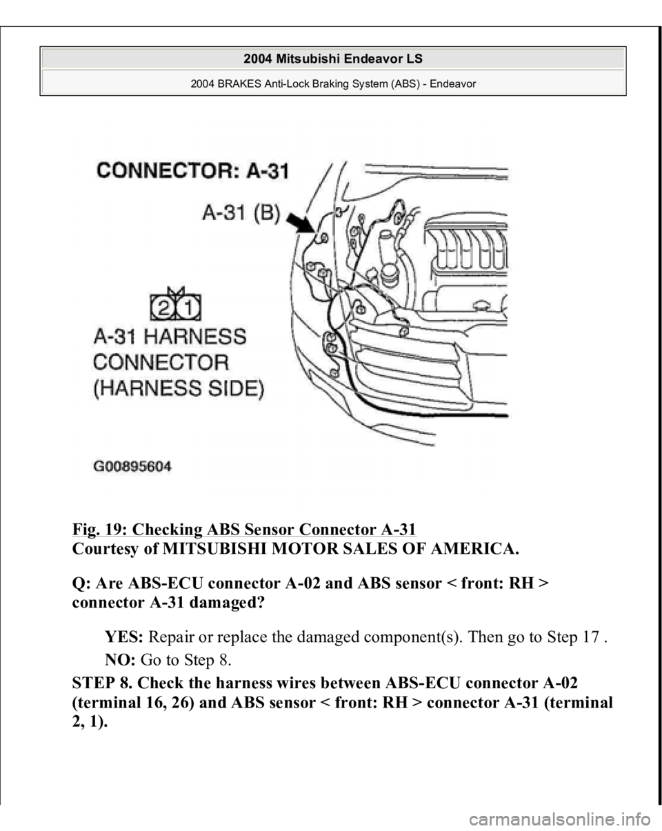
Fig. 19: Checking ABS Sensor Connector A
-31
Courtesy of MITSUBISHI MOTOR SALES OF AMERICA.
Q: Are ABS-ECU connector A-02 and ABS sensor < front: RH >
connector A-31 damaged?
YES: Repair or replace the damaged component(s). Then go to Step 17 .
NO: Go to Step 8.
STEP 8. Check the harness wires between ABS-ECU connector A-02
(terminal 16, 26) and ABS sensor < front: RH > connector A-31 (terminal
2, 1).
2004 Mitsubishi Endeavor LS
2004 BRAKES Anti-Lock Braking System (ABS) - Endeavor
Page 38 of 3870
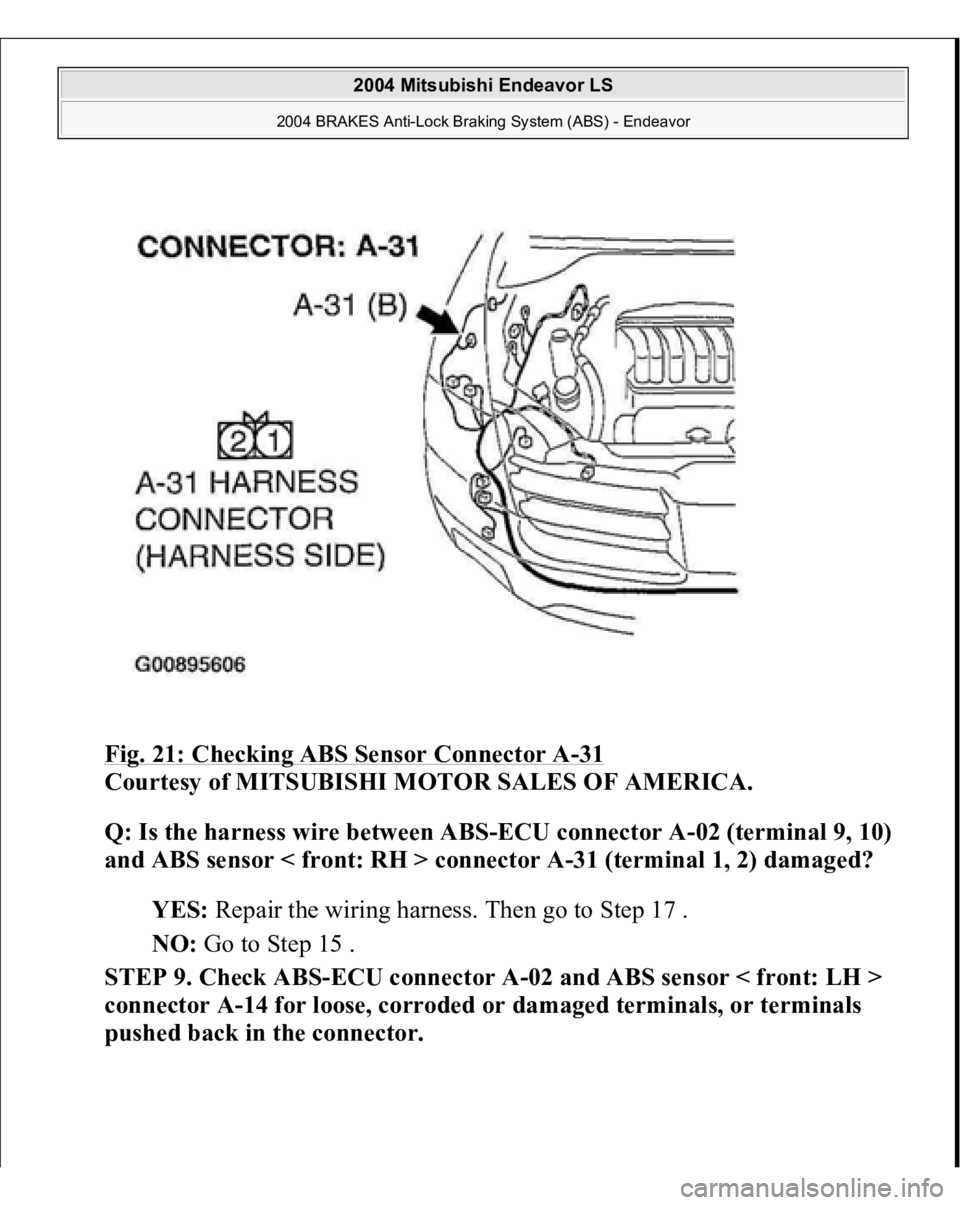
Fig. 21: Checking ABS Sensor Connector A
-31
Courtesy of MITSUBISHI MOTOR SALES OF AMERICA.
Q: Is the harness wire between ABS-ECU connector A-02 (terminal 9, 10)
and ABS sensor < front: RH > connector A-31 (terminal 1, 2) damaged?
YES: Repair the wiring harness. Then go to Step 17 .
NO: Go to Step 15 .
STEP 9. Check ABS-ECU connector A-02 and ABS sensor < front: LH >
connector A-14 for loose, corroded or damaged terminals, or terminals
pushed back in the connector.
2004 Mitsubishi Endeavor LS
2004 BRAKES Anti-Lock Braking System (ABS) - Endeavor
Page 40 of 3870
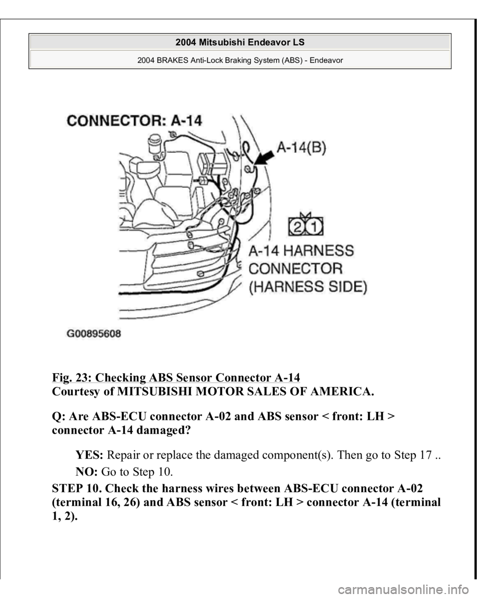
Fig. 23: Checking ABS Sensor Connector A
-14
Courtesy of MITSUBISHI MOTOR SALES OF AMERICA.
Q: Are ABS-ECU connector A-02 and ABS sensor < front: LH >
connector A-14 damaged?
YES: Repair or replace the damaged component(s). Then go to Step 17 ..
NO: Go to Step 10.
STEP 10. Check the harness wires between ABS-ECU connector A-02
(terminal 16, 26) and ABS sensor < front: LH > connector A-14 (terminal
1, 2).
2004 Mitsubishi Endeavor LS
2004 BRAKES Anti-Lock Braking System (ABS) - Endeavor