MITSUBISHI GALANT 1989 Service Repair Manual
Manufacturer: MITSUBISHI, Model Year: 1989, Model line: GALANT, Model: MITSUBISHI GALANT 1989Pages: 1273, PDF Size: 37.62 MB
Page 141 of 1273
ENGINE
J
Tensioner armTensioner arm
TSB Revision
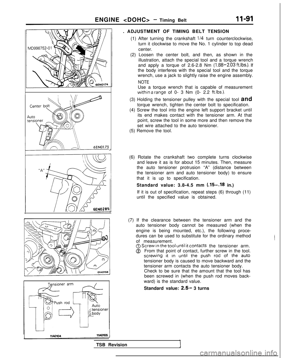
. ADJUSTMENT OF TIMING BELT TENSION
(1) After turning the crankshaft
l/4 turn counterclockwise,
turn it clockwise to move the No. 1 cylinder to top dead
center.
(2) Loosen the center bolt, and then, as shown in the illustration, attach the special tool and a torque wrench
and apply a torque of 2.6-2.8 Nm (1.88-2.03
ft.lbs.). If
the body interferes with the special tool and the torque
wrench, use a jack to slightly raise the engine assembly.
NOTE
Use a torque wrench that is capable of measurement
within a range of 0- 3 Nm (0- 2.2 ftlbs.).
(3) Holding the tensioner pulley with the special tool and torque wrench, tighten the center bolt to specification.
(4) Screw the tool into the engine left support bracket until its end makes contact with the tensioner arm. At that
point, screw the tool in some more and then remove the
set wire attached to the auto tensioner.
(5) Remove the tool.
(6) Rotate the crankshaft two complete turns clockwise and leave it as is for about 15 minutes. Then, measure
the auto tensioner protrusion “A” (distance between
the tensioner arm and auto tensioner body) to ensure
that it is up to specification.
Standard value: 3.8-4.5 mm
(.15-.I8 in.)
If it is out of specification, repeat steps (6) through (11)
until the specified value is obtained.
(7) If the clearance between the tensioner arm and the auto tensioner body cannot be measured (when the
engine is being mounted, etc.), the following proce-
dures can be used to substitute for the ordinary method
of measurement.
@j Screw in
the tool until it
contacts the tensioner arm.
@From that point of contact, further screw in the tool.
screwing it in
until the push
rod
of the auto
tensioner body is caused to move backward and the
tensioner arm contacts the auto tensioner body.
Check to be sure that the amount that the tool has
been screwed in (when the push rod moves back-
ward) is the standard value.
Standard value:
2.5- 3 turns
Page 142 of 1273
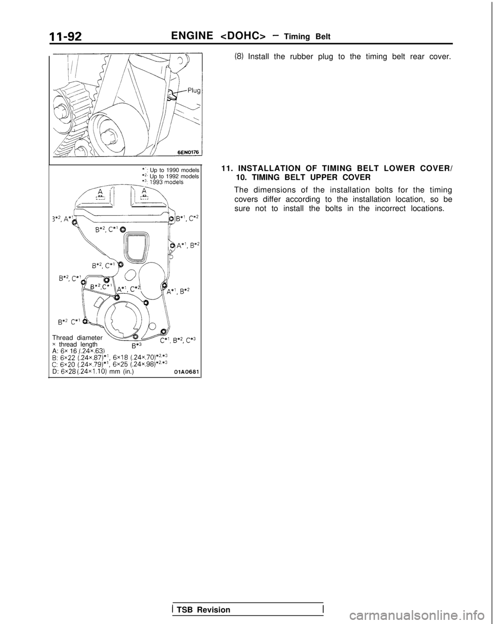
(8) Install the rubber plug to the timing belt rear cover.
ENGINE
- Timing Belt
*‘: Up to 1990 models*>. Up to 1992 models A*
B+2
C*’
Thread diameterx thread length
A: 6x
16 1.24x.63)B: 6x22
(.24?87j*‘, 6x18 (.24~.70)*~,*~C: 6x20
(.24x.79)*‘,
6x25 (.24x.98)*2,*3D: 6x28 (.24x1.10)
mm (in.)OlA0681
11. INSTALLATION OF TIMING BELT LOWER COVER/
10. TIMING BELT UPPER COVER
The dimensions of the installation bolts for the timing covers differ according to the installation location, so be
sure not to install the bolts in the incorrect locations.
1 TSB Revision
Page 143 of 1273
13-1
FUEL
CONTENTSM’ISAA--
AUTO-CRUISE CONTROL SYSTEM.............
.
332
AUTO-CRUISE CONTROL ............................. 408
SERVICE ADJUSTMENT PROCEDURES .................397
Accelerator Cables
inspectron and Adjustment ........
.
398 Auto-cruise
Control System Inspection
..............397
Individual Parts Inspection ......................
401SPECfAL
TOOLS
.....................................
333
SPECIFICATIONS .................................... 332
TROUBLESHOOTING ................................. 334
Auto-cruise Control Components Location ..........368
Auto-cruise Control
Related Harnesses
..........365
Check Chart
Check Chart
Circuit Diagram ................................
371input Checking................................
.
366
On-board Diagnostic Checking ......................
361Troubleshooting Quick-reference Chart
.
334
Troubleshooting Quick-reference Chart
ENGINE CONTROL...............................
.
328
ENGINE CONTROL ..................................
330
SERVICE ADJUSTMENT PROCEDURES .................329
Accelerator Cable inspectron and Adjustment
...........329
Accelerator Switch Inspection and Adjustment ..........329
SPECIFICATIONS ....................................
328
TROUBLESHOOTlNG................................
.
328
Accelerator
Cable and Accelerator Pedal .............
.
328
FUEL SYSTEM
FUEL FILTER .........................................
327
FUEL LINE AND VAPOR LINE
.
326
FUEL LINE AND VAPOR LINE
.
324
FUEL TANK
.
322
FUELTANK
.
318
GENERAL INFORMATION ............................ 196
ON-VEHICLE INSPECTION OF MFI
COMPONENTS
......251
Air Conditioning Switch and A/C Compressor Clutch Relay .....................................
285
Barometric Pressure Sensor .................... 266
Boost Meter
311Camshaft Position Sensor ........................
.
277Closed Throttle Position Switch
.....................
.
274
Component Location .............................
251Components Inspection Pocedure
................. 255
Crankshaft Position Sensor ..................... 280EGR
Solenord
...................
.
307EGR Temperature Sensor
.............
.
288Engrne Control Module Power Ground
................
.
257
Engine Coolant Temperature Sensor ..................
268Evaporative Emission Purge Solenoid .................
.
307
Fuel Pressure Solenoid
307Fuel Pressure Test...............................
.
312
Fuel Pump ...................................... 258
Heated Oxygen Sensor ............................ 290
Idle Air Control Motor (Stepper Motor) ................
238Ignition Coil and Ignition Power Transistor .............
.
302
Ignition Switch-ST .................................. 284
Ignition Switch-ST and Park/Neutral Position Switch .....284
Injectors .......................................
295Inspection of Engine Control Module Terminal
Voltage .......................................
.
315
Intake Air Temperature Sensor .......................263
Knock Sensor
Power Steering Pressure Switch ......................
284Power Supply and Ignition Switch ...................
.
255Resistor
..............................
.
298Terminal Voltage Check Chart
......................
.
315Throttle Position Sensor
..........................
.
270Turbocharger Waste Gate Solenoid
.........
.
309 Vehicle
Speed Sensor
............................... 284
Volume Air Flow Sensor ............................
261SERVICE ADJUSTMENT PROCEDURES ...............
.
245
Basic
idle Speed Adjustment .......................
.
245
Closed Throttle Position Switch (Fixed
SAS)Adjustment ......................................
.
250
Curb
Idle Speed Inspection
..........................245Throttle Body (Throttle Valve Area) Cleaning
...........
.
248Throttle Position Sensor Adjustment
..................
.
248
SPECIALTOOLS...................................
.
204
SPECIFICATIONS ...................................
201TROUBLESHOOTING ...............................
.
205
Check Engine/Malfunction Indicator Lamp ..............205
Circuit Diagram .................................... 214
Clear Memory of Diagnostic Trouble Code .............
211Explanation and Precaution Related to Harness
Checking ......................................
.
205Explanation of Troubleshooting Procedures
............
.
205Failsafe/Back-up Functions List
.....................
.
211Fuel tank and Fuel Line
............................
.
244
Read Out Diagnostic Trouble Code ...................
211Troubleshooting Table
.............................
.
208(CONTINUED ON NEXT PAGE)
Page 144 of 1273
13-2
FUEL SYSTEM
..........
FUEL FILTER ....................................
FUEL LINE AND VAPOR LINE .....................FUELTANK....................................
.
GENERAL INFORMATION ........................
ON-VEHICLE INSPECTION OF MFI
COMPONENTS . .
Air
Conditionrng Switch and A/C CompressorClutch Relay ......
.
.............
Barometric Pressure Sensor .........
Camshaft Position Sensor ...........
Closed Throttle Position Switch ...........
Component Location .............
Components
Inspectron Procedure .......
.
Crankshaft Positron Sensor ............
EGR Solenoid
. . .3. .
115..,.113
. 109
. . 3
. . . 38
83
536961384173101EGR Temperature Sensor
.
85
Enqine Control Module Power Ground ......
.
....
45
Engine Coolant Temperature Sensor ...............
55Evaporative Emission Purge Solenord..............
.
99
Fuel Pressure ...............................
102Fuel Pump
...................................
.
46
Idle Speed Control Motor (DC Motor) ................
.
93
Idle Speed Control Motor Positron Sensor ............
.
64
lgnitron Co11 and Ignition Power Transistor .........
.
96
Ignition Switch-ST ..........................
77Ignition Switch-ST and Park/Neutral Position Switch
...78
Injectors..................................
.
90
Inspection of
Engrne Control Module Terminal
Voltage .........
.
..........................
105Intake Air Temperature Sensor ..................
.
51Oxygen Sensor
............................
.
87Power Steering Pressure Switch
..................
.
81Power Supply
.........................
.
42
Terminal Voltage Check Chart ......................
106Throttle Positron Sensor.....................
.
57Vehicle Speed Sensor
.........................
.
80
Volume Air Flow Sensor .........................
49
SERVICE ADJUSTMENT PROCEDURES .................
32
Basic
Idle Speed Adjustment ...................
.
33
Curb Idle Speed Inspection ..........................
32Throttle Body (Throttle Valve Area) Cleaning........
.
35
Throttle Positron Sensor Adjustment ................
35
SPECIAL TOOLS 7
.................
...................
SPECIFICATIONS ....................................
5
TROUBLESHOOTING .................................
8
Check Engine/Malfunction Indicator Lamp ..............
10Crrcuit Diagram.................................
.
20
Clear Memory of Diagnostic Trouble Code ............
17Explanation and Precaution Related to HarnessChecking......................................
.
9Explanation of Troubleshooting Procedures
...........
.
8
Failsafe/Back-up Functions List ....................
16Fuel Tank and Fuel Lrne.........................
.
32Read Out of Diagnostic Trouble Code
...............
.
16Troubleshooting Table
.........................
.
13
FUEL SYSTEM
116
FUEL FILTER .......................................
195
FUEL LINE AND VAPOR LINE ........................
195
FUEL TANK ........................................ 195
GENERAL INFORMATION ............................
116
ON-VEHICLE INSPECTION OF MFI
COMPONENTS
Air Conditioning Switch and A/C Compressor Clutch Relay .............................
Barometric Pressure Sensor .................
Camshaft Position Sensor ....................
Closed Throttle Position Switch ................
Component Location .......................
Components Inspectron Pocedure
..............
Crankshaft Position Sensor .................
EGR Solenoid
EGR Temperature Sensor
Engine Control Module Power Ground ..........
Engine Coolant Temperature Sensor .............
Evaporative Emission Purge Solenoid ............
Fuel Pressure Test ...........................
Fuel Pump ..................................
IAC Valve Positon Sensor
......................
Idle Air Control Motor (DC Motor) ..............
lgnrtion Coil and Ignition Power Transistor
.......
.
Ignition Switch-ST ...........................
Ignition Switch-ST and Park/Neutral Position Switch
Injectors ....................................
Inspection of Engine Control Module Terminal
Voltage .....................................
Intake Air Temperature Sensor .................
Oxygen Sensor .............................
Power Steering Pressure
Swatch..............
.
Power Supply ...............................
Terminal Voltage Check Chart ..................
Throttle Position Sensor .......................
Vehicle Speed Sensor ......................... . . . . 139
176
154
165
16013914216
7
..,_ 191177146
155
189192
147
162
184
186
171172181
192152
179
175
143
192
157
173
Volume Air Flow Sensor ...........................
.
150
SERVICE ADJUSTMENT PROCEDURES
...............
.
133
Basic Idle Speed Adjustment 133
Closed Throttle Position Switch and Throttle Position
Sensor Adjustment .................................
136Curb Idle Speed Inspection
.........................
.
133Fixed SAS Adjustment
.............................
.
138Throttle Body (Throttle Valve Area) Cleaning
...........
.
136
SPECIAL TOOLS
...................................
.
119
SPECIFICATIONS 118
.... ..............................
TROUBLESHOOTING ..................
.............
119
Check Engine/Malfunction Indicator Lamp ..............
120Circuit Diagram...................................
.
128Clear Memory of Diagnostic Trouble Code
............
.
126Explanation and Precaution Related to Harness
Checking ........................................
.
119Explanation of Troubleshooting Procedures
............
.
119Failsafe/Back-up
Fuctions List
........................
126
Fuel Tank and Fuel Line .............................
133Read Out of Diagnostic Trouble Code ................
.
126
Troubleshooting Table ..............................
123
Page 145 of 1273
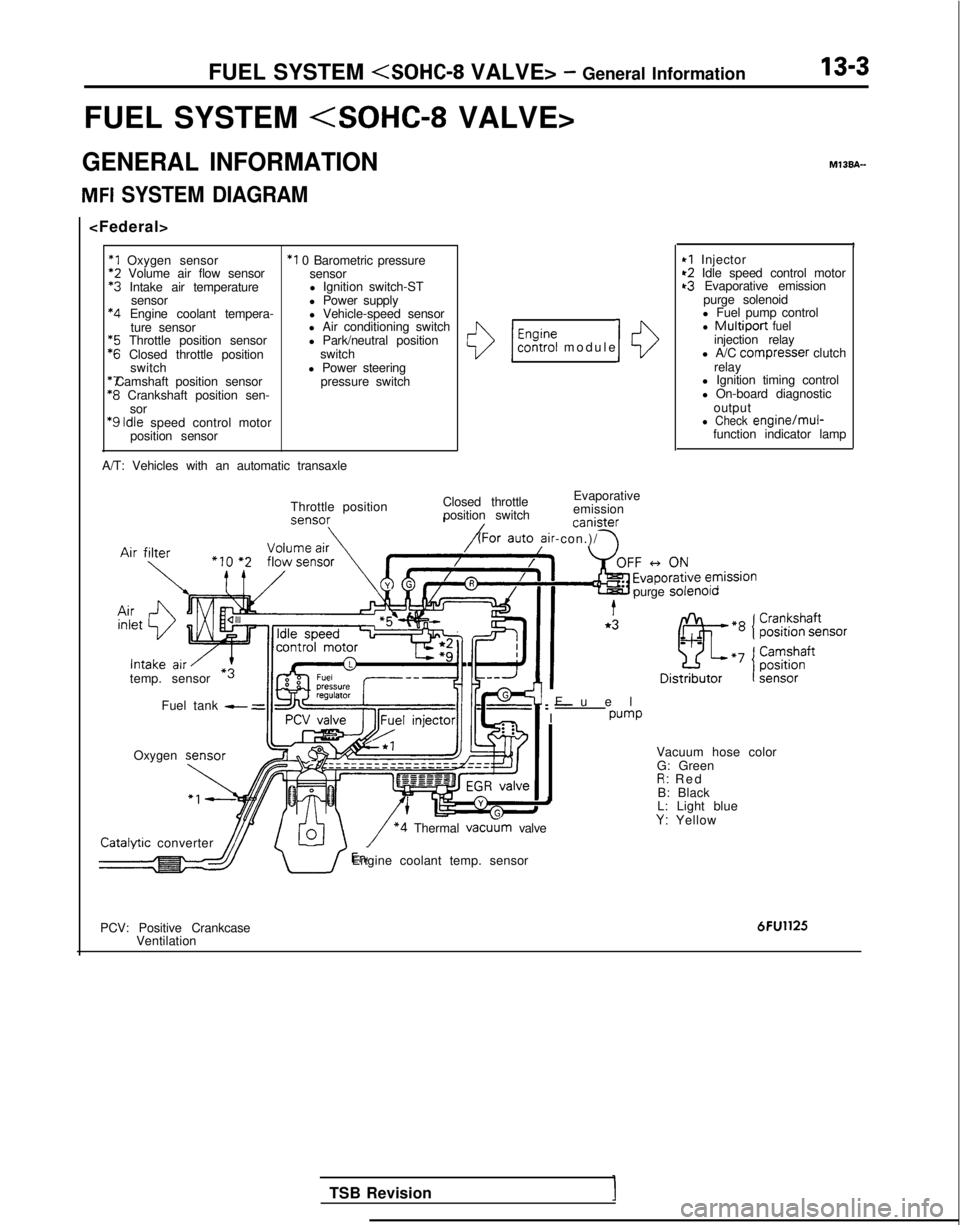
FUEL SYSTEM
FUEL SYSTEM
GENERAL INFORMATION
MFI SYSTEM DIAGRAM
*1 Oxygen sensor
*2
Volume air flow sensor *3
Intake air temperature
sensor *4
Engine coolant tempera-
ture sensor *5
Throttle position sensor *6
Closed throttle position
switch *7 Camshaft position sensor
*8
Crankshaft position sen-
sor
‘9 Idle
speed control motor
position sensor
*I 0 Barometric pressure sensor
l Ignition switch-ST
l Power supply
l Vehicle-speed sensor
l Air conditioning switch
l Park/neutral position
switch
l Power steering pressure switch
A/T: Vehicles with an automatic transaxle
()/ $%?i modul
e
Closed throttle Evaporative
position switch emission canister
ir-con.)/ \
10
Throttle position
temp. sensor Fuel tank
- =
Oxygen M13BA-
I
*I Injector~2 Idle speed control motort3 Evaporative emission
purge solenoid
l Fuel pump control
l Multiport fuelinjection relay
l A/C compresser clutch
relay
l Ignition timing control
l On-board diagnostic
output
l Check engine/mul-function indicator lamp
Fue
l
: -
I
pump
purge
solenolo Catalvtic
converter
\/ *4 Thermal vacu
G: Green
R: Re
d
B: Black
L: Light blue
Y: Yellow
dJJ/ U’Engine coolant temp. sensor
PCV: Positive Crankcase Ventilation
6FU1125
TSB Revision
Page 146 of 1273
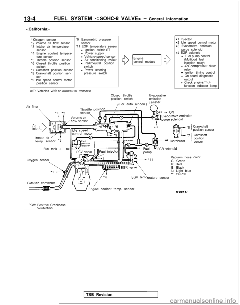
13-4FUEL SYSTEM
*2 Volume
air
flow sensor$3 Intake air temperature
sensor
*4 Engine coolant tempera-ture sensor
“5 Throttle position sensor‘6 Closed throttle position switch
*7 Camshaft position sensor*8 Crankshaft position sen-
sor
*9 Idle speed control motor position sensor “I 0
Barometric pressure
sensor
‘11 EGR temperature sensor
l Ignition switch-STl Power supply
l
Vehrcle-speed sensor
l Air conditioning switch
l Park/neutral position
switch
l Power steering pressure switchI13
Engrnecontrol module10
rl Injectort2 Idle speed control motorr3 Evaporative emission
purge solenoid
r4 EGR solenoidl Fuel pump control
(Multiport fuel
injection relay)
l A/C compresser clutchrelay0 Ignition timing control
l On-board diagnostic
output
l Check engine/muj-function indicator lamp
A/T: Vehicles
with an automatrc
transaxle
Closed throttleposition switch Evaporative
emission
/(For auto air-con.) can’ster
/ n
Vacuum hose
G: Green
R: Red
B: Black L: Light blue
Y: Yellow
erature sensor Air
filter
Fuel tank - =
Oxygen sensor
\ U /Eni coolant temp. sensor1FUO447
Crankshaft
position sensor
Camshaft
position
sensor
color
PCV: Posrtive
Crankcase
TSB Revision
Page 147 of 1273
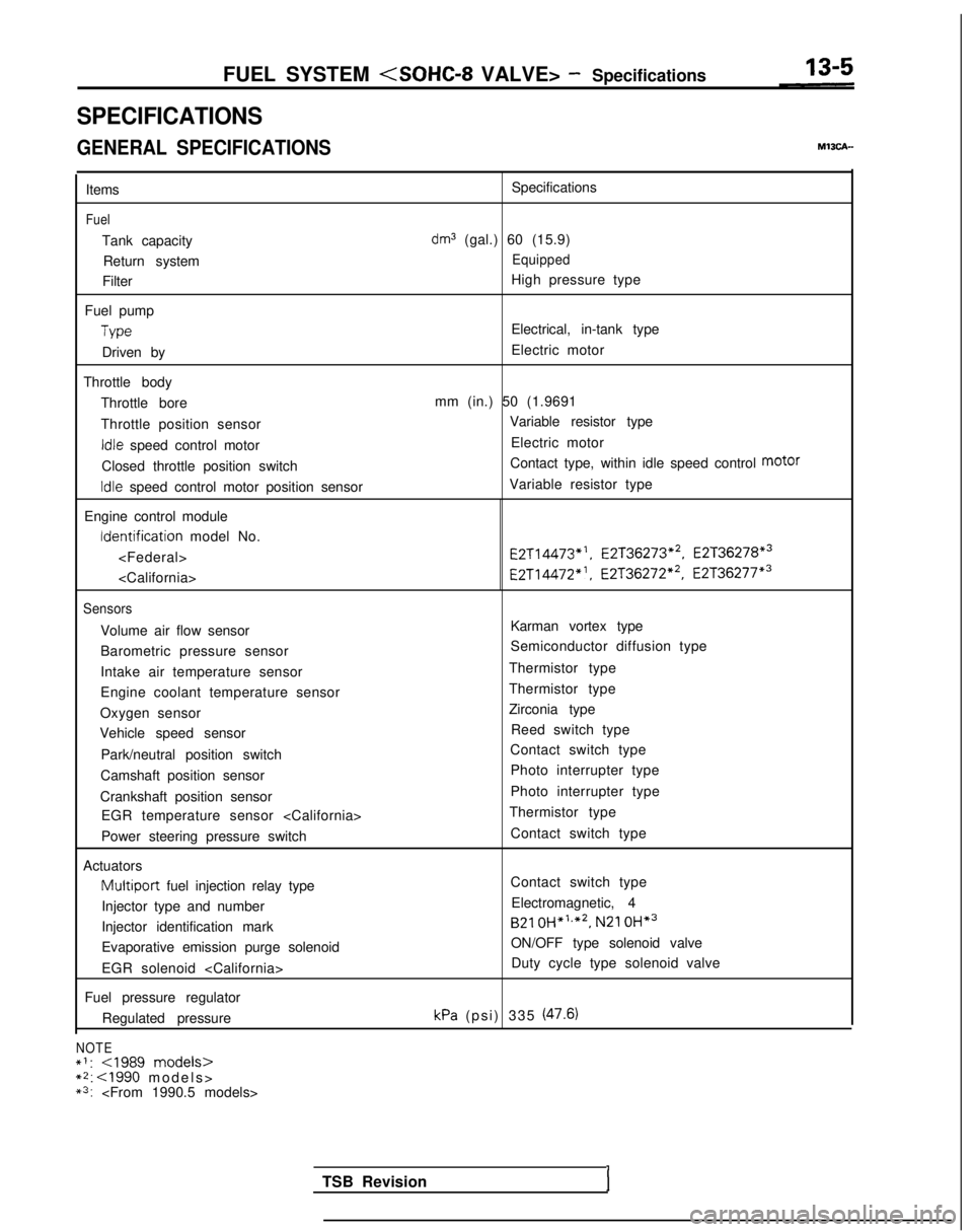
FUEL SYSTEM
SPECIFICATIONS
GENERAL SPECIFICATIONS
Items
Fuel
Tank capacity
Return system
Filter
Fuel pump
Type
Driven by
Throttle body Throttle bore
Throttle position sensor
Idle speed control motor
Closed throttle position switch
Idle speed control motor position sensor
Engine control module Identification
model No.
Sensors
Volume air flow sensor
Barometric pressure sensor
Intake air temperature sensor
Engine coolant temperature sensor
Oxygen sensor
Vehicle speed sensor
Park/neutral position switch
Camshaft position sensor
Crankshaft position sensor EGR temperature sensor
Power steering pressure switch
Actuators
Multiport fuel injection relay type
Injector type and number
Injector identification mark
Evaporative emission purge solenoid
EGR solenoid
Fuel pressure regulator Regulated pressure
NOTE*I:
*3:
dm3 (gal.) 60 (15.9)
Equipped
High pressure type
Electrical, in-tank type
Electric motor
mm (in.) 50 (1.9691 Variable resistor type
Electric motor
Contact type, within idle speed control motor
Variable resistor type E2T14473*‘,
E2T36273*2, E2T36278*3
E2T14472”. E2T36272*2, E2T36277*3
Karman vortex type
Semiconductor diffusion type
Thermistor type
Thermistor type
Zirconia type Reed switch type
Contact switch type
Photo interrupter type
Photo interrupter type
Thermistor type
Contact switch type
Contact switch typeElectromagnetic, 4
B21 OH*‘,*2,
N21 OH*3
ON/OFF type solenoid valve
Duty cycle type solenoid valve
kPa (psi) 335 (47.6)
TSB RevisionI
Page 148 of 1273
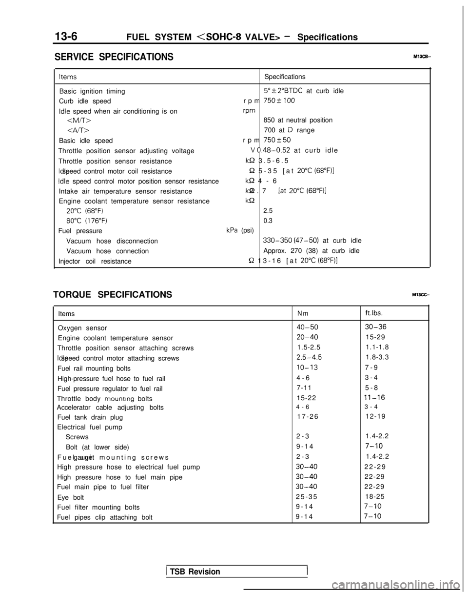
13-6
FUEL SYSTEM
SERVICE SPECIFICATIONSMl3CE.
ItemsSpecifications
Basic ignition timing
5”?2”BTDC at curb idle
Curb idle speed rpm
7502 100Idle
speed when air conditioning is on rpm
-am-r>850 at neutral position
4A>700 at D range
Basic idle speed rpm
750+50
Throttle position sensor adjusting voltageV 0.48-0.52 at curb idl
e
Throttle position sensor resistance
k-2 3.5-6.
5
Idle speed control motor coil resistance
Q 5-35 [at 20°C (68”F)l
Idle
speed control motor position sensor resistance
M-2 4-
6
Intake air temperature sensor resistance kQ 2.7 [at
20°C (68”F)l
Engine coolant temperature sensor resistancekc2
20°C (68°F)2.5
80°C (176°F)0.3
Fuel pressurekPa (psi)
Vacuum hose disconnection
330-350 (47-50) at curb idle
Vacuum hose connection Approx. 270 (38) at curb idle
Injector coil resistance
R 13-16 [at 20°C (68”F)]
TORQUE SPECIFICATIONSMIICC-
Items
Oxygen sensor
Engine coolant temperature sensor
Throttle position sensor attaching screws Idle speed control motor attaching screws
Fuel rail mounting bolts
High-pressure fuel hose to fuel rail
Fuel pressure regulator to fuel rail
Throttle body mounting
bolts
Accelerator cable adjusting bolts
Fuel tank drain plug
Electrical fuel pump Screws
Bolt (at lower side)
Fuel unit mounting screws gauge
High pressure hose to electrical fuel pump
High pressure hose to fuel main pipe
Fuel main pipe to fuel filter
Eye bolt
Fuel filter mounting bolts
Fuel pipes clip attaching boltNmft.lbs.
40-5030-36
20-4015-29
1.5-2.5 1.1-1.8
2.5-4.51.8-3.3
IO-137-
9
4-6 3-4
7-11 5-8
15-22
11-16
4-
6
3-4
17-26 12-19
2-3 1.4-2.2
9-14
7-10
2-
3
1.4-2.2
30-4022-2
9
30-4022-29
30-4022-29
25-3
5
18-25
9-14
7-10
9-1
4
7-10
1 TSB Revision
Page 149 of 1273
FUEL SYSTEM
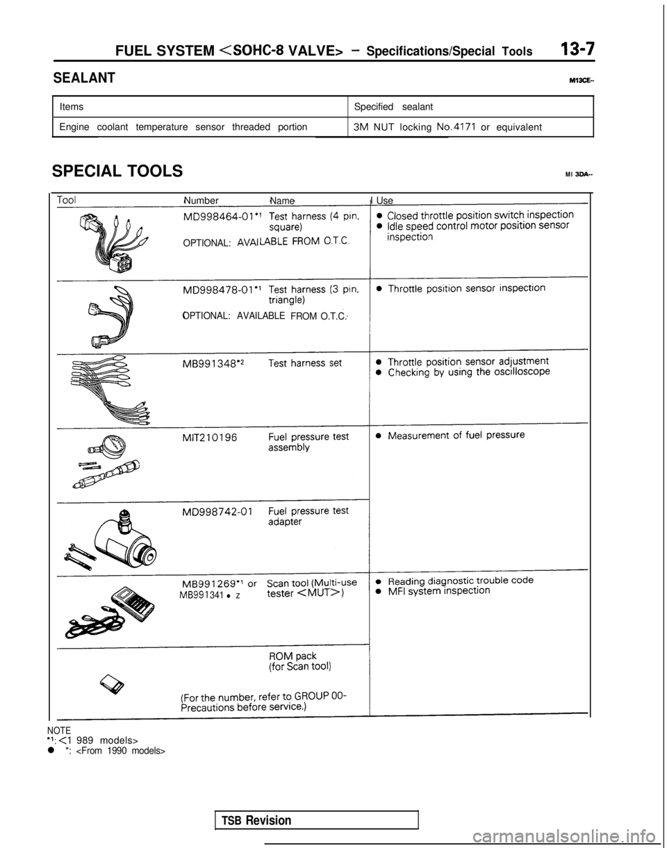
SEALANTM13CE-
Items Specified sealant
Engine coolant temperature sensor threaded portion 3M
NUT locking
No.4171 or equivalent
SPECIAL TOOLS
Ml JDA-
Number
NameI Use
OPTIONAL: AVAI
OPTIONAL: AVAILABLE FROM O.T.C.
MB991 341 l z
NOTE
‘1: <1
989 models>l *:
TSB Revision
Page 150 of 1273
13-8
FUEL SYSTEM
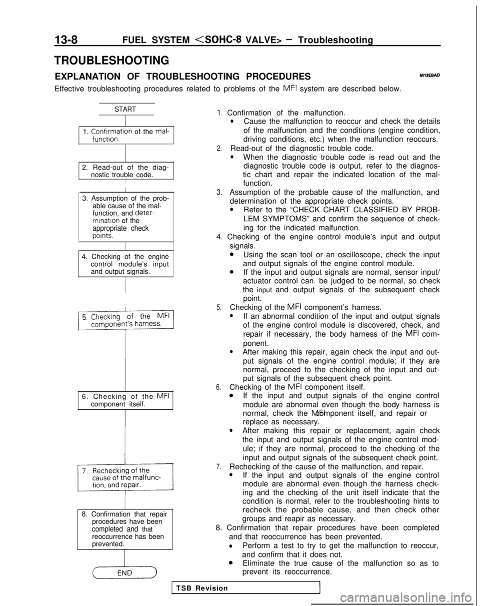
TROUBLESHOOTING
EXPLANATION OF TROUBLESHOOTING PROCEDURESMlBEBAD
Effective troubleshooting procedures related to problems of the MFI
system are described below.
START
1. Confrrmatron of the mal-functron.
2. Read-out of the diag-
nostic trouble code.
I
I
3. Assumption of the prob-
able cause of the mal-
function, and deter-
mrnatron of theappropriate checkpoints.
4. Checking of the engine
control module’s inputand output signals.
6. Checking of the
MFIcomponent itself.
8. Confirmation that repair procedures have been
completed and thatreoccurrence has been
prevented.
I. Confirmation of the malfunction.lCause the malfunction to reoccur and check the details
of the malfunction and the conditions (engine condition,
driving conditions, etc.) when the malfunction reoccurs.
2.Read-out of the diagnostic trouble code.
lWhen the diagnostic trouble code is read out and the diagnostic trouble code is output, refer to the diagnos-
tic chart and repair the indicated location of the mal- function.
3.Assumption of the probable cause of the malfunction, and
determination of the appropriate check points.
lRefer to the “CHECK CHART CLASSIFIED BY PROB-
LEM SYMPTOMS” and confirm the sequence of check-
ing for the indicated malfunction.
4. Checking of the engine control module’s input and output signals.
0Using the scan tool or an oscilloscope, check the input
and output signals of the engine control module.
aIf the input and output signals are normal, sensor input/
actuator control can. be judged to be normal, so check
the input and output signals of the subsequent check point.
5.Checking of the MFI
component’s harness.lIf an abnormal condition of the input and output signals
of the engine control module is discovered, check, and
repair if necessary, the body harness of the
MFI com-
ponent.
lAfter making this repair, again check the input and out- put signals of the engine control module; if they are
normal, proceed to the checking of the input and out-
put signals of the subsequent check point.
6.Checking of the MFI
component itself.aIf the input and output signals of the engine control
module are abnormal even though the body harness is
normal, check the MFI component itself, and repair or
replace as necessary.
lAfter making this repair or replacement, again check
the input and output signals of the engine control mod-
ule; if they are normal, proceed to the checking of the
input and output signals of the subsequent check point.
7.Rechecking of the cause of the malfunction, and repair.lIf the input and output signals of the engine control
module are abnormal even though the harness check-
ing and the checking of the unit itself indicate that the
condition is normal, refer to the troubleshooting hints to recheck the probable cause, and then check other
groups and reapir as necessary.
8. Confirmation that repair procedures have been completed and that reoccurrence has been prevented.
lPerform a test to try to get the malfunction to reoccur,
and confirm that it does not.
aEliminate the true cause of the malfunction so as to
prevent its reoccurrence.
TSB Revision