clock MITSUBISHI L200 2013 (in English) Owner's Guide
[x] Cancel search | Manufacturer: MITSUBISHI, Model Year: 2013, Model line: L200, Model: MITSUBISHI L200 2013Pages: 362, PDF Size: 21.07 MB
Page 319 of 362
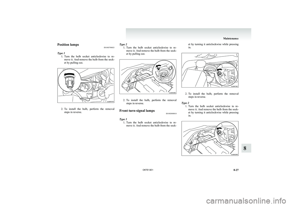
Position lampsE01003700833
Type 1 1.Turn the bulb socket anticlockwise to re-
move it. And remove the bulb from the sock-
et by pulling out.
2. To install the bulb, perform the removal
steps in reverse.
Type 2
1.Turn the bulb socket anticlockwise to re-
move it. And remove the bulb from the sock-
et by pulling out.
2. To install the bulb, perform the removal
steps in reverse.
Front turn-signal lamps E01003800818
Type 1
1.Turn the bulb socket anticlockwise to re-
move it. And remove the bulb from the sock-
et by turning it anticlockwise while pressing
in.
2. To install the bulb, perform the removal
steps in reverse.
Type 2 1.Turn the bulb socket anticlockwise to re-
move it. And remove the bulb from the sock-
et by turning it anticlockwise while pressing
in.
Maintenance
8-27
OKTE13E1
8
Page 320 of 362
2.To install the bulb, perform the removal
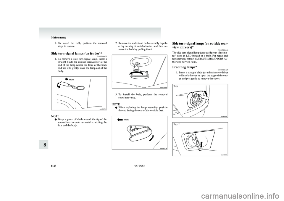
steps in reverse.Side turn-signal lamps (on fender)* E01003900633
1.To remove a side turn-signal lamp, insert a
straight blade (or minus) screwdriver at the
end of the lamp nearer the front of the body
and use it to gently lever the lamp out of the
body.
Front
NOTE
l Wrap a piece of cloth around the tip of the
screwdriver in order to avoid scratching the
lens and the body.
2. Remove the socket and bulb assembly togeth-
er by turning it anticlockwise, and then re-
move the bulb by pulling it out.
3. To install the bulb, perform the removal
steps in reverse.
NOTE l When replacing the lamp assembly, push in
the end facing the rear of the vehicle first.
FrontSide turn-signal lamps (on outside rear-
view mirrors)* E01003900646
The side turn-signal lamp (on outside rear-view mir-
ror) uses an LED instead of a bulb. For repair and
replacement, contact a MITSUBISHI MOTORS Au-
thorized Service Point.Front fog lamps* E01004001537
1.Insert a straight blade (or minus) screwdriver
with a cloth over its tip at the edge of the cov-
er and pry gently to remove the cover.
Type 1Type 2
Maintenance
8-28 OKTE13E1
8
Page 321 of 362
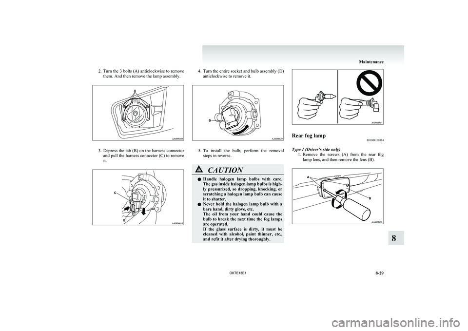
2.Turn the 3 bolts (A) anticlockwise to remove
them. And then remove the lamp assembly.
3. Depress the tab (B) on the harness connector
and pull the harness connector (C) to remove
it.
4. Turn the entire socket and bulb assembly (D)
anticlockwise to remove it.
5. To install the bulb, perform the removal
steps in reverse.
CAUTIONl Handle halogen lamp bulbs with care.
The gas inside halogen lamp bulbs is high-
ly pressurized, so dropping, knocking, or
scratching a halogen lamp bulb can cause
it to shatter.
l Never hold the halogen lamp bulb with a
bare hand, dirty glove, etc.
The oil from your hand could cause the
bulb to break the next time the fog lamps
are operated.
If the glass surface is dirty, it must be
cleaned with alcohol, paint thinner, etc.,
and refit it after drying thoroughly.Rear fog lamp E01004100384
Type 1 (Driver’s side only)
1.Remove the screws (A) from the rear fog
lamp lens, and then remove the lens (B).
Maintenance
8-29
OKTE13E1
8
Page 322 of 362
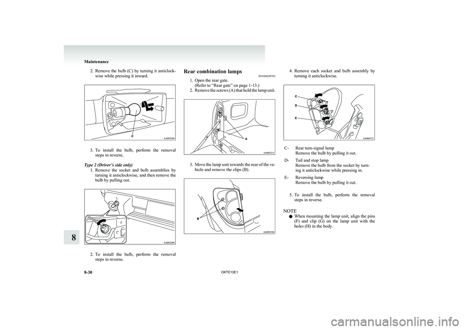
2.Remove the bulb (C) by turning it anticlock-
wise while pressing it inward.
3. To install the bulb, perform the removal
steps in reverse.
Type 2 (Driver’s side only) 1.Remove the socket and bulb assemblies by
turning it anticlockwise, and then remove the
bulb by pulling out.
2. To install the bulb, perform the removal
steps in reverse.
Rear combination lamps E01004200763
1. Open the rear gate.
(Refer to “Rear gate” on page 1-13.)
2. Remove the screws (A) that hold the lamp unit.
3.Move the lamp unit towards the rear of the ve-
hicle and remove the clips (B).
4. Remove each socket and bulb assembly by
turning it anticlockwise.C-Rear turn-signal lamp
Remove the bulb by pulling it out.D-Tail and stop lamp
Remove the bulb from the socket by turn-
ing it anticlockwise while pressing in.E-Reversing lamp
Remove the bulb by pulling it out.
5. To install the bulb, perform the removal
steps in reverse.
NOTE l When mounting the lamp unit, align the pins
(F) and clip (G) on the lamp unit with the
holes (H) in the body.
Maintenance
8-30 OKTE13E1
8
Page 323 of 362
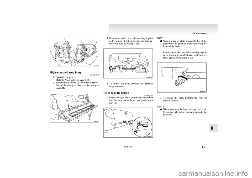
High-mounted stop lampE01004500577
1. Open the rear gate.
(Refer to “Rear gate” on page 1-13.)
2. Remove the 8 screws (A) from the inner sur-
face of the rear gate. Remove the rear gate
cover (B).
3. Remove the socket and bulb assembly togeth-
er by turning it anticlockwise, and then re-
move the bulb by pulling it out.
4. To install the bulb, perform the removal
steps in reverse.
Licence plate lamps E01004601025
1.Insert a straight blade (or minus) screwdriver
into the lamp assembly and pry gently to re-
move it.
NOTE
l Wrap a piece of cloth around the tip of the
screwdriver in order to avoid scratching the
lens and the body.
2. Remove the socket and bulb assembly togeth-
er by turning it anticlockwise, and then re-
move the bulb by pulling it out.
3. To install the bulb, perform the removal
steps in reverse.
NOTE l When mounting the lamp unit, put the hook
(A) on the right side of the lamp unit into the
body first.
Maintenance
8-31
OKTE13E1
8
Page 326 of 362
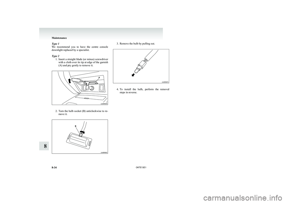
Type 1
We recommend you to have the centre console
downlight replaced by a specialist.
Type 2 1.Insert a straight blade (or minus) screwdriver
with a cloth over its tip at edge of the garnish
(A) and pry gently to remove it.
2. Turn the bulb socket (B) anticlockwise to re-
move it.
3. Remove the bulb by pulling out.
4. To install the bulb, perform the removal
steps in reverse.
Maintenance
8-34 OKTE13E1
8
Page 349 of 362
4
4-wheel drive operation 4-35A
Accessory (Installation) 04
Accessory socket 5-72
Active Stability & Traction Control (ASTC) 4-43
Additional equipment 8-19
Air conditioning Automatic air conditioning 5-08
Important operation tips for the air condition-
ing 5-12
Manual air conditioning 5-03
Air purifier 5-12
Airbag 2-27
Antenna 5-50
Anti-lock brake system (ABS) 4-40 Warning lamp 4-41
Armrest (Double cab) 2-07
Ashtray 5-70
Audio Audio system anti-theft feature 5-48
Error codes 5-42
Handling of compact discs 5-48
LW/MW/FM electronic tuning radio with CD
player 5-13
Steering wheel remote control switch 5-40
Automatic air conditioning 5-08
Automatic transmission Sports Mode 4A/T, 5A/
T 4-17 Fluid 8-07,9-20
Selector lever operation 4-17
Selector lever position indicator 4-18
Selector lever positions 4-18
Sports mode 4-19
Sports mode indicator 4-19
B
Battery 8-10 Discharged battery (Emergency starting) 6-02
Specification 9-16
Bleeding the fuel system 6-05
Bluetooth® 2.0 interface 5-51
Bonnet 8-03
Bottle holder 5-79
Brake Anti-lock brake 4-40
Brake assist system 4-40
Braking 4-39
Fluid 8-08,9-20
Parking brake 4-06
Parking brake lever stroke 8-16
Pedal free play 8-16
Warning lamp 3-08
C
Cargo loads 4-50
Catalytic converter 8-02
Cautions on handling of 4-wheel drive vehi-
cles 4-37
Central door locks 1-07
Centre console downlight 5-75 Bulb capacity 8-24
Replacement 8-34
Centre information display 3-10
Changing a fuse 8-22
Changing gears 4-15
Check engine warning lamp 3-08
Child restraint 2-13
Child-protection rear doors 1-08
Cigarette lighter 5-71
Cleaning Exterior of your vehicle 7-03
Genuine leather 7-02
Interior of your vehicle 7-02
Plastic, vinyl leather, etc 7-02
Sunroof 7-05
Waxing 7-04
Clock 3-19,5-73
Clutch Fluid 8-09,9-20
Pedal free play 8-15
Coat hook 5-80
Combination headlamps and dipper switch 3-30
Convenient hook 5-79
Coolant (engine) 8-06,9-20
Cruise control 4-46 Switch 4-46
Cup holder 5-78
Curtain airbag system 2-35
D
Demister (rear window) 3-40
Diesel particulate filter (DPF) 4-13
Differential oil 9-20
Digital clock 3-19,5-73
Dimensions 9-03
Dipper (High/Low beam change) 3-31
Door courtesy lamps 5-75 Replacement 8-33
Doors Central door locks 1-07
Child-protection 1-08
Lock and unlock 1-06
Driving, alcohol and drugs 4-02
E
Easy select 4WD 4-22
Economical driving 4-02
Electric window control 1-08
Alphabetical index
1