driver seat adjustment MITSUBISHI LANCER 2005 Workshop Manual
[x] Cancel search | Manufacturer: MITSUBISHI, Model Year: 2005, Model line: LANCER, Model: MITSUBISHI LANCER 2005Pages: 788, PDF Size: 45.98 MB
Page 286 of 788

FUEL FILLER LID
BODY42-8
FUEL FILLER LID
REMOVAL AND INSTALLATIONM1421002500277
Pre-removal and Post-installation Operation
•Rear Seat Removal and Installation (Refer to GROUP
52A, Rear Seat P.52A-28.)
•Front Scuff Plate (Driver's Seat Side), Rear Scuff Plate
(Driver's Side), Centre Pillar Lower Trim (Driver's Side),
Quarter Trim (Driver's Side) Removal and Installation
(Refer to GROUP 52A, Trims P.52A-11.)
18M0109W0570AQ
AC005996
AC005973
3
54
3
2 1
5.0 ± 1.0 N·m
AC
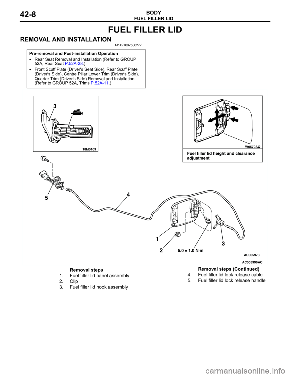
Fuel filler lid height and clearance
adjustment
Removal steps
1. Fuel filler lid panel assembly
2. Clip
3. Fuel filler lid hook assembly4. Fuel filler lid lock release cable
5. Fuel filler lid lock release handleRemoval steps (Continued)
Page 459 of 788

FOG LAMP
CHASSIS ELECTRICAL54A-71
FOG LAMP
SERVICE SPECIFICATIONM1542000300343
SPECIAL TOOLM1542000600894
TROUBLESHOOTINGM1542000701292
When the front fog lamp switch is turned to ON with
the tail lamp or the headlamp on (the tail lamp switch
or the headlamp switch is ON), the fog lamp relay
turns on, and the fog lamps will illuminate.
If the tail lamps or the headlamps are turned off with
the lighting switch OFF while the fog lamps are on,
the front fog lamps turn off at the same time to
prevent unattended operation.
If the tail lamps are turned off by the headlamp
automatic shutdown function, the fog lamps turn off
at the same time. However, if the tail lamps illuminate
again, the fog lamps do not.
The front fog lamps are controlled by the Smart
Wiring System (SWS). For troubleshooting, refer to
respective Groups below.
•Not using SWS monitor: GROUP 54B, SWS
Troubleshooting P.54B-38.
•Using SWS monitor: GROUP 54C, SWS
Troubleshooting P.54C-22.
ON-VEHICLE SERVICE
FRONT FOG LAMP AIMING CHECKM1542001100438
After setting the vehicles to the following condition,
adjust the front fog lamp aiming.
•Check that the tyre inflation pressure is at the
value indicated on the tyre pressure labels.
•Set the vehicle to the unladen condition and park
it on a level surface.
•Have a single person (approximately 75 kg) sit in
the driver’s seat.•Run the engine at a speed of 2000 r/min to fully
charge the battery.
Turn on the front fog lamps and check that the
illumination is within the standard value range.
Standard value: Illuminates to within 40
metres
CAUTION
For the fog lamp which is not being measured,
disconnect that fog lamp’s connector if possible
so that it does not illuminate while carrying out
the adjustment. Furthermore, make sure that the
light axis does not get shifted when
re-connecting the connector.
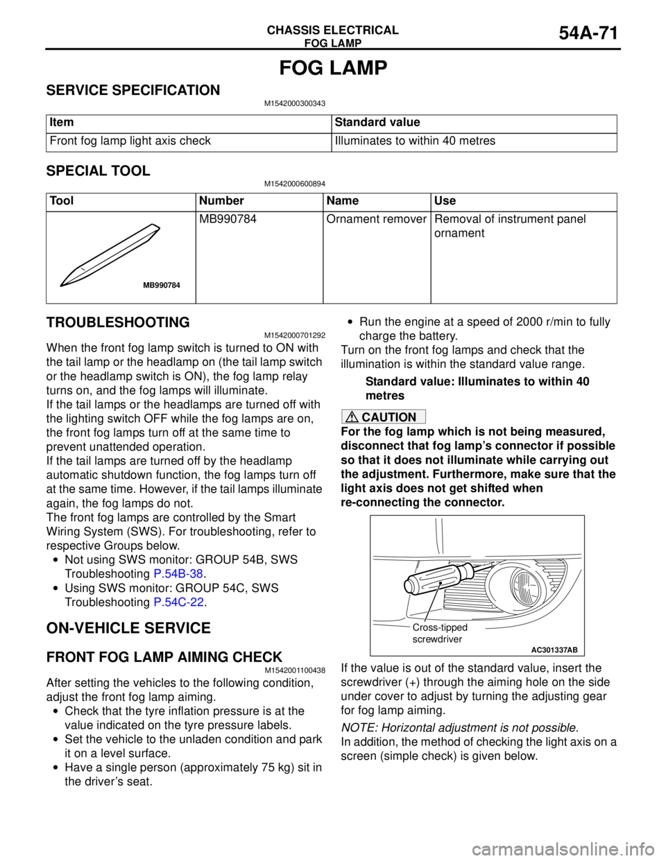
If the value is out of the standard value, insert the
screwdriver (+) through the aiming hole on the side
under cover to adjust by turning the adjusting gear
for fog lamp aiming.
NOTE: Horizontal adjustment is not possible.
In addition, the method of checking the light axis on a
screen (simple check) is given below. Item Standard value
Front fog lamp light axis check Illuminates to within 40 metres
Tool Number Name Use
MB990784 Ornament remover Removal of instrument panel
ornament
MB990784
AC301337
Cross-tipped
screwdriver
AB