warning light MITSUBISHI LANCER 2017 8.G User Guide
[x] Cancel search | Manufacturer: MITSUBISHI, Model Year: 2017, Model line: LANCER, Model: MITSUBISHI LANCER 2017 8.GPages: 385, PDF Size: 14.34 MB
Page 54 of 385
Supplemental Restraint System (SRS) - airbag
Seat and restraint systems 4-27
4
N00407900318
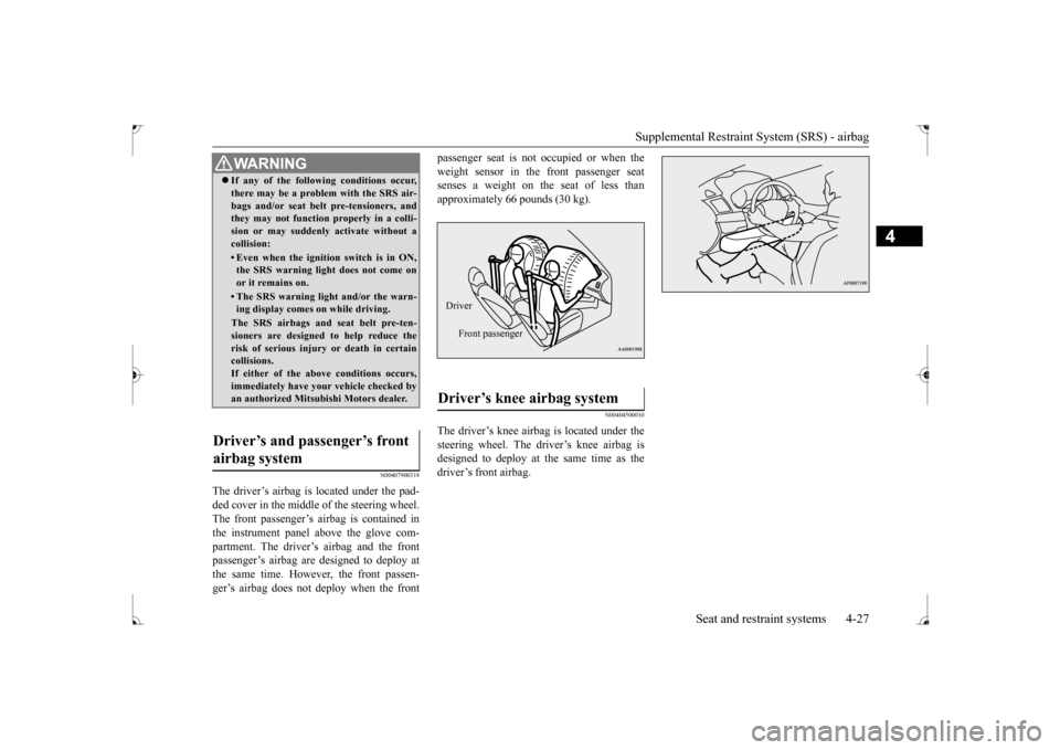
The driver’s airbag is located under the pad- ded cover in the middle of the steering wheel. The front passenger’s airbag is contained in the instrument panel above the glove com-partment. The driver’s airbag and the front passenger’s airbag are designed to deploy at the same time. However, the front passen-ger’s airbag does not deploy when the front
passenger seat is not occupied or when the weight sensor in the front passenger seat senses a weight on the seat of less than approximately 66 pounds (30 kg).
N00404500010
The driver’s knee airbag is located under the steering wheel. The driver’s knee airbag is designed to deploy at the same time as thedriver’s front airbag.
WA R N I N G If any of the following conditions occur, there may be a problem with the SRS air- bags and/or seat belt pre-tensioners, and they may not function properly in a colli- sion or may suddenly activate without acollision:• Even when the ignition switch is in ON,the SRS warning light does not come on or it remains on.• The SRS warning light and/or the warn-ing display comes on while driving.The SRS airbags and seat belt pre-ten-sioners are designed to help reduce the risk of serious injury or death in certaincollisions. If either of the above conditions occurs, immediately have your vehicle checked byan authorized Mitsubishi Motors dealer.
Driver’s and passenger’s front airbag system
Driver’s knee airbag system Driver
Front passenger
BK0237700US.bo
ok 27 ページ 2016年4月15日 金曜日 午前11時28分
Page 66 of 385
5
Features and controlsBreak-in recommendation
s ..............................................................5-3
Keys ..........................................
.......................................................5-3
Electronic immobilizer (Anti-thef
t starting system) ........................5-4
Keyless entry system (if so equipped) ..............................................5-7Free-hand Advanced Security Transmitter (F.A.S.T.-key) (if so
equipped) ..................................................5-12
Door locks .......................
...............................................................5-34
Power door locks ............
...............................................................5-37
“Child safety locks” for
rear door ..................................................5-38
Trunk lid ...................................
.....................................................5-39
Inside emergency trunk lid
release ................................................5-40
Theft-alarm system (if so
equipped) ...............................................5-41
Power windows ...............
...............................................................5-43
Sunroof (if so equipped
) .........................................
........................5-46
Parking brake ..................
...............................................................5-48
Steering wheel tilt lock lever .........................................................5-49Inside day/night rearview
mirror ...................................................5-50
Outside rearview mirr
ors ...............................................................5-51
Ignition switch ......
.................................................
........................5-52
Steering wheel lock
................................................
........................5-54
Starting and stopping the e
ngine ....................................................5-55
Manual transaxle (if so equipped) ..................................................5-57Continuously variable transmissi
on (CVT) (if so equipped)..........5-59
Electronically controlled 4WD system (if so equipped).................5-68 All-wheel driving opera
tion ...........................................................5-70
Cautions on handling of all-wheel drive vehicles ..........................5-71Service brake ..................
...............................................................5-72
Brake assist system
................................................
........................5-73
Anti-lock braking syst
em .....................................
......................... 5-74
Active Stability Control (ASC
) (if so equipped) ............................ 5-76
Power steering system
..........................................
......................... 5-79
Cruise control (if so eq
uipped) ....................................................... 5-80
Tire pressure monitoring
system ................................................... 5-84
Rear-view camera (if so
equipped)..............
................................... 5-88
Instrument cluster
.................................................
......................... 5-90
Multi-information disp
lay ....................................
......................... 5-91
Indicator light, warning light, and information screen display list .................................................
.......................................... 5-112
Indicators .................................
.................................................... 5-123
Warning lights ................
.................................................
............. 5-124
Information screen disp
lay ...................................
....................... 5-125
Combination headlights and dimmer switch ............................... 5-127 Headlight leveling switch (if
so equipped)................................... 5-132
Turn signal lever ..
.................................................
....................... 5-133
Hazard warning flasher
switch .................................................... 5-133
Front fog light switch (if so
equipped) ......................................... 5-134
Wiper and washer swit
ch ......................................
....................... 5-134
Electric rear window def
ogger switch ......................................... 5-138
Horn switch .............................
.................................................... 5-139
Link System (if so equi
pped) ....................................................... 5-139
Bluetooth
® 2.0 interface (if so
equipped)..................................... 5-139
USB input terminal
...............................................
....................... 5-160
Sun visors ......................
.................................................
............. 5-163
12 V power outlet ..........
.................................................
............. 5-163
Interior lights .................
.................................................
............. 5-164
Storage spaces ................
.................................................
............. 5-166
BK0237700US.bo
ok 1 ページ 2016年4月15日 金曜日 午前11時28分
Page 85 of 385
Free-hand Advanced Security Transmitter (F.A.S.T.-key) (if so equipped) 5-20 Features and controls
5
N00560100105
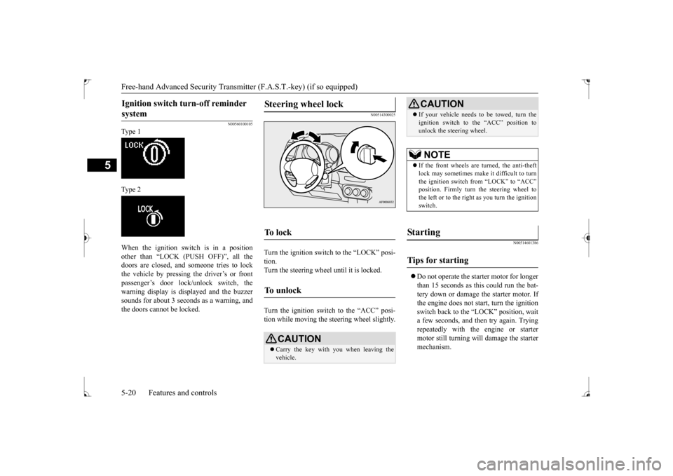
Ty p e 1 Ty p e 2 When the ignition switch is in a position other than “LOCK (PUSH OFF)”, all the doors are closed, and someone tries to lock the vehicle by pressing the driver’s or frontpassenger’s door lock/unlock switch, the warning display is displayed and the buzzer sounds for about 3 seconds as a warning, andthe doors cannot be locked.
N00514300025
Turn the ignition switch to the “LOCK” posi-tion.Turn the steering wheel until it is locked. Turn the ignition switch to the “ACC” posi- tion while moving the steering wheel slightly.
N00514601386
Do not operate the starter motor for longer than 15 seconds as this could run the bat-tery down or damage the starter motor. If the engine does not start, turn the ignition switch back to the “LOCK” position, waita few seconds, and then try again. Trying repeatedly with the engine or starter motor still turning will damage the startermechanism.
Ignition switch turn-off reminder system
Steering wheel lock
To l o c k
To u n l o c k
CAUTION Carry the key with you when leaving the vehicle.
If your vehicle needs to be towed, turn the ignition switch to the “ACC” position to unlock the steering wheel.NOTE
If the front wheels are turned, the anti-theft lock may sometimes make it difficult to turn the ignition switch from “LOCK” to “ACC”position. Firmly turn the steering wheel to the left or to the right as you turn the ignition switch.
St arting
Tips for starting
CAUTION
BK0237700US.bo
ok 20 ページ 2016年4月15日 金曜日 午前11時28分
Page 86 of 385
Free-hand Advanced Security Transmit
ter (F.A.S.T.-key) (if so equipped)
Features and controls 5-21
5
If the engine will not start because the bat- tery is weak or discharged, refer to “Jump-starting the engine” on page 8-2 for instructions. A longer warm up period will only con- sume extra fuel. The engine is warmed up enough for driving when the bar graph ofthe engine coolant temperature display starts to move. Refer to “Interrupt display screen (With ignition
switch in the “ON”
position)” on page 5-101.
Your vehicle is equipped with an electroni- cally controlled fuel injection system. This isa system that automatically controls fuel injection. There is no need to depress the accelerator pedal when starting the engine.The starter motor should not be run for more than 15 seconds at a time. To prevent battery drain, wait a few secondsbetween attempts to restart the engine. 1. Make sure all occupants are properly seated with seat belts fastened. 2. Make sure the parking brake is applied. 3. Press and hold the brake pedal downfirmly with your right foot. 4. Press and hold the clutch pedal all the way down (manual transaxle). 5. On vehicles with manual transaxle, place the gearshift lever in the “N” (Neutral) position.On vehicles with continuously variable transmission (CVT) make sure the selec- tor lever is in the “P” (PARK) position.
6. While pushing the ignition switch from “LOCK” (PUSH OFF) to “LOCK” (PUSH ON), set the ignition switch to the“ON” position and confirm that all warn-ing lights and warning displays are oper- ating properly. 7. Without pressing the accelerator pedal,slowly turn the ignition switch to the “START” position to start the engine. Release the ignition switch when theengine starts.
After several attempts, you may experience that the engine still does not start.
WA R N I N G Never run the engine in a closed or poorly ventilated area any longer than is needed to move your vehicle out of the area. Car-bon monoxide gas, which is odorless and extremely poisonous, could build up and cause serious injury or death.CAUTION Do not push-start the vehicle.Do not run the engine at high rpms or drive at high speeds until the engine has had a chance to warm up. Release the ignition switch as soon as the engine starts. Otherwise, the starter motorwill be damaged.
Starting the engine
NOTE
For models equipped with a manual trans- axle, the starter will not operate unless the clutch pedal is fully depressed (Clutch inter-lock). This is a safety feature.
NOTE
On vehicles with CVT, the starter will not operate unless the selector lever is in the “P” (PARK) or “N” (NEUTRAL) position. For safety reasons, start the engine in the “P” (PARK) position so that the wheels arelocked.NOTE
Minor noises may be heard on engine start- up. These will disappear as the engine warms up.
When the engine is hard to start
BK0237700US.bo
ok 21 ページ 2016年4月15日 金曜日 午前11時28分
Page 91 of 385
Free-hand Advanced Security Transmitter (F.A.S.T.-key) (if so equipped) 5-26 Features and controls
5
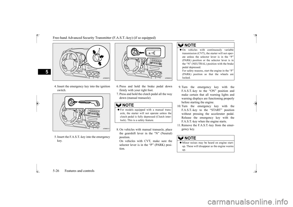
4. Insert the emergency key into the ignition switch. 5. Insert the F.A.S.T.-key into the emergency key.
6. Press and hold the brake pedal down firmly with your right foot.7. Press and hold the clutch pedal all the way down (manual transaxle). 8. On vehicles with manual transaxle, place the gearshift lever in the “N” (Neutral) position. On vehicles with CVT, make sure theselector lever is in the “P” (PARK) posi- tion.
9. Turn the emergency key with the F.A.S.T.-key to the “ON” position and make certain that all warning lights and warning displays are functioning properlybefore starting the engine.
10. Turn the emergency key with the
F.A.S.T.-key to the “START” positionwithout pressing the accelerator pedal. Release the emergency key with the F.A.S.T.-key when the engine starts.
11. Remove the F.A.S.T.-key from the emer-
gency key.
NOTE
For models equipped with a manual trans- axle, the starter will
not operate unless the
clutch pedal is fully depressed (Clutch inter-lock). This is a safety feature.
NOTE
On vehicles with continuously variable transmission (CVT), the starter will not oper- ate unless the selector lever is in the “P” (PARK) position or the selector lever is in the “N” (NEUTRAL) position with the brakepedal depressed. For safety reasons, start the engine in the “P” (PARK) position so that the wheels arelocked.NOTE
Minor noises may be heard on engine start- up. These will disappear as the engine warms up.
BK0237700US.bo
ok 26 ページ 2016年4月15日 金曜日 午前11時28分
Page 107 of 385
Theft-alarm system (if so equipped) 5-42 Features and controls
5
4. The system has entered the armed stage after about 20 seconds, when the theft- alarm indicator (A) flashing becomes slower.The theft-alarm indicator (A) continues to flash while the system is in the armed stage.
N00510401197
The alarm will be activated if any of the fol-lowing occur while the vehicle is parked andthe system is armed.
One of the doors is opened without using the remote control transmitter or the F. A . S . T. - k e y. The engine hood or the trunk lid is opened.
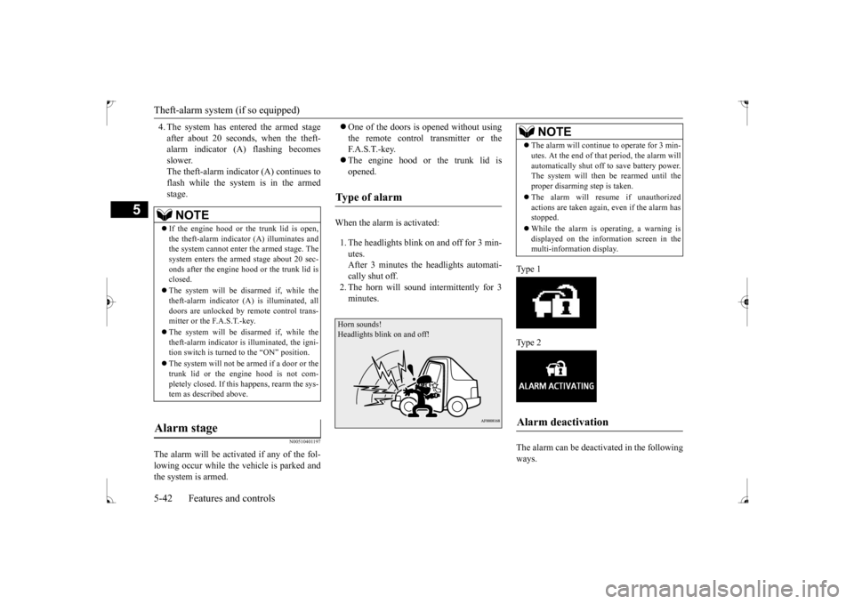
When the alarm is activated: 1. The headlights blink on and off for 3 min- utes.After 3 minutes the headlights automati- cally shut off. 2. The horn will sound intermittently for 3minutes.
Ty p e 1 Ty p e 2 The alarm can be deactivated in the following ways.
NOTE
If the engine hood or the trunk lid is open, the theft-alarm indicator (A) illuminates and the system cannot enter the armed stage. The system enters the armed stage about 20 sec-onds after the engine hood or the trunk lid is closed. The system will be disarmed if, while the theft-alarm indicator (A) is illuminated, all doors are unlocked by remote control trans-mitter or the F.A.S.T.-key. The system will be disarmed if, while the theft-alarm indicator is illuminated, the igni- tion switch is turned to the “ON” position. The system will not be
armed if a door or the
trunk lid or the engine hood is not com- pletely closed. If this happens, rearm the sys-tem as described above.
Alarm stage
Type of alarm
Horn sounds!Headlights blink on and off!
NOTE
The alarm will continue to operate for 3 min- utes. At the end of that period, the alarm will automatically shut off to save battery power. The system will then
be rearmed until the
proper disarming step is taken. The alarm will resume if unauthorized actions are taken again, even if the alarm hasstopped. While the alarm is operating, a warning is displayed on the information screen in the multi-information display.
Alarm deactivation
BK0237700US.bo
ok 42 ページ 2016年4月15日 金曜日 午前11時28分
Page 113 of 385
Parking brake 5-48 Features and controls
5
N00511401439
To park the vehicle, first bring it to a com- plete stop and fully engage the parking brake.For vehicles with a manual transaxle, move the gear shift lever to 1st (on a uphill) or “R” (Reverse) (on a downhill) position.For vehicles with a continuously variable transmission (CVT), set the selector lever to “P” (PARK) position.
When parking on a hill, apply the parking brake and turn the front wheels toward thecurb on a downhill grade, away from the curb on an uphill grade.
Be sure to close the sunroof completely when washing the vehicle or when leaving the vehicle. Do not put any wax on the weatherstrip (black rubber) around the sunroof opening. If it is waxed, the weatherstrip cannot maintain a weatherproof seal with the sunroof. After washing the vehicle or after rain be sure to wipe off any water that is on the sun-roof before operating it. Operating the sunroof repeatedly with the engine turned off will run down the battery. Operate the sunroof only while the engine is running.
Parking brake
NOTE
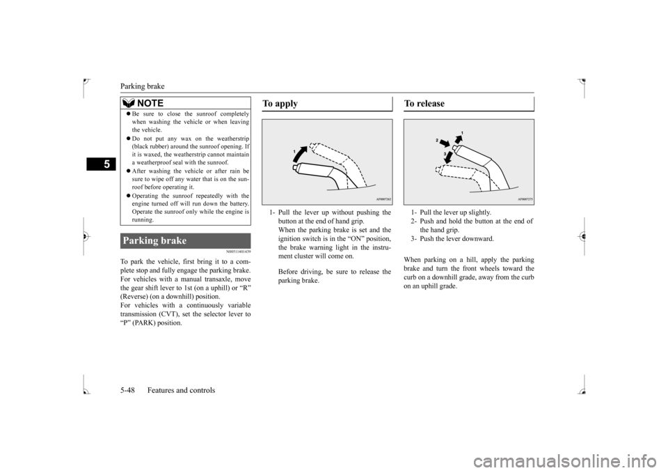
To apply 1- Pull the lever up without pushing the
button at the end of hand grip. When the parking brake is set and theignition switch is in the “ON” position, the brake warning light in the instru- ment cluster will come on. Before driving, be sure to release the parking brake.
To r e l e a s e 1- Pull the lever up slightly. 2- Push and hold the button at the end of
the hand grip.
3- Push the lever downward.
BK0237700US.bo
ok 48 ページ 2016年4月15日 金曜日 午前11時28分
Page 114 of 385
Steering wheel tilt lock lever Features and controls 5-49
5
N00511501270
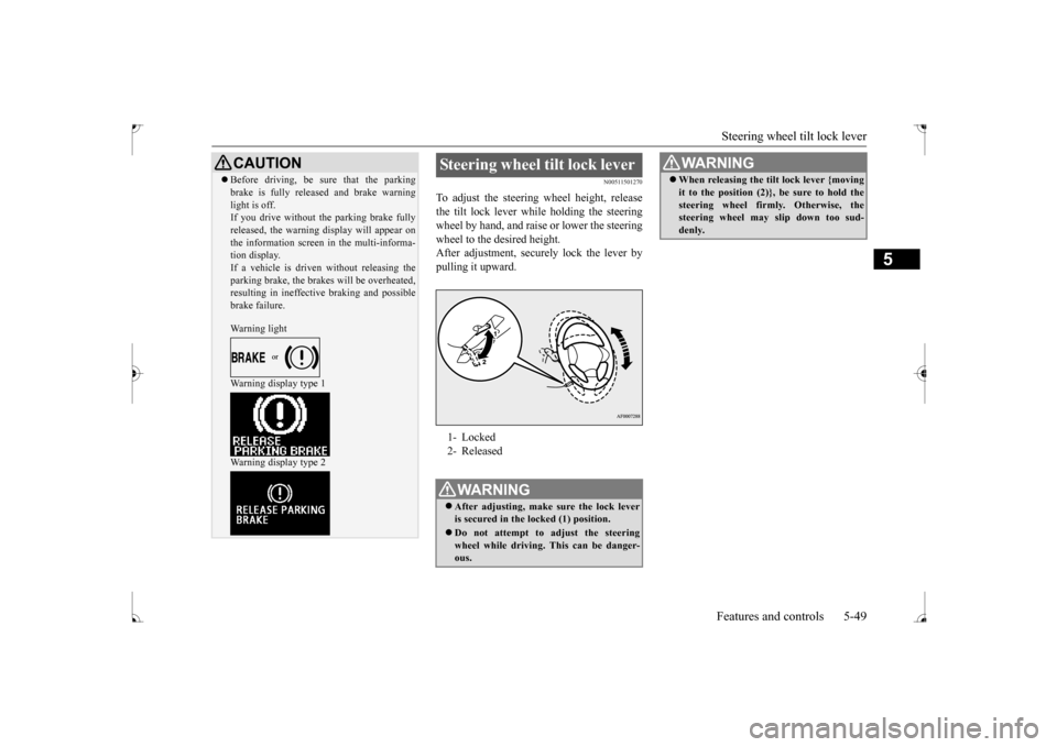
To adjust the steering wheel height, release the tilt lock lever while holding the steeringwheel by hand, and raise or lower the steering wheel to the desired height. After adjustment, securely lock the lever bypulling it upward.
CAUTION Before driving, be sure that the parking brake is fully released and brake warning light is off. If you drive without the parking brake fully released, the warning display will appear onthe information screen in the multi-informa- tion display. If a vehicle is driven without releasing theparking brake, the brakes will be overheated, resulting in ineffective braking and possible brake failure. Warning light Warning display type 1 Warning display type 2
Steering wheel tilt lock lever 1- Locked 2- ReleasedWA R N I N G After adjusting, make sure the lock lever is secured in the locked (1) position. Do not attempt to adjust the steering wheel while driving. This can be danger-ous.
When releasing the tilt lock lever {moving it to the position (2)}, be sure to hold the steering wheel firmly. Otherwise, the steering wheel may slip down too sud- denly. WA R N I N G
BK0237700US.bo
ok 49 ページ 2016年4月15日 金曜日 午前11時28分
Page 121 of 385
Starting and stopping the engine 5-56 Features and controls
5
7. Turn the ignition switch to the “ON” posi- tion and make certain that all warning lights are functioning properly beforestarting the engine.8. Turn the ignition switch to the “START” pedal. Release the key when the enginestarts.
After several attempts, you may experience that the engine still does not start. 1. Make sure that all electric devices, such as lights, air conditioning blower and rearwindow defogger, are turned off.
2. While depressing the brake pedal on vehi- cles equipped with continuously variable transmission (CVT) or the clutch pedal on the vehicles equipped with manual trans-axle, press the accelerator pedal halfway and hold it there, then crank the engine. Release the accelerator pedal, immedi-ately after the engine starts. 3. If the engine still will not start, the engine could be flooded with too much gasoline.While depressing the brake pedal on vehi-cles equipped with CVT or the clutch pedal on the vehicles
equipped with man-
ual transaxle, push the accelerator pedalall the way down and hold it there, then crank the engine for 5 to 6 seconds. Return the ignition switch to the “LOCK”position and release the accelerator pedal. Wait a few seconds, and then crank the engine again for 5 to 6 seconds whiledepressing the brake pedal or the clutch pedal, but do not push the accelerator pedal. Release the ignition key if theengine starts. If the engine fails to start, repeat these procedures. If the engine still will not start, contact your local Mitsubi-shi Motors dealer or a repair facility of your choice for assistance.
When the ambient temperature is -4 °F (-20 °C) or lower on vehicles with CVT, itmay not be possible to start from a standstill even with the selector lever in the “D” (DRIVE) or “R” (REVERSE) position.This phenomenon occurs because the trans-axle has not warmed up sufficiently; it does not indicate a problem. If it occurs, place the selector lever in the “P” (PARK) position andlet the engine idle for at least 10 minutes. The transaxle will warm up, and you will be able to start normally.Do not leave the vehicle during warm-up operation.
N00542301102
1. Bring the vehicle to a complete stop. 2. Fully engage the parking brake while depressing the brake pedal. 3. For vehicles with a manual transaxle, turn the ignition switch to the “LOCK” posi- tion to stop the engine, and then move thegearshift lever to the 1st (on a uphill) or “R” (Reverse) (on a downhill) position.
NOTE
On vehicles with CVT, the starter will not operate unless the selector lever is in the “P” (PARK) or “N” (NEUTRAL) position. For safety reasons, start the engine in the “P” (PARK) position so that the wheels arelocked.NOTE
Minor noises may be heard on engine start- up. These will disappear as the engine warms up.
When the engine is hard to start
Startability of continuously vari- able transmission (CVT) vehicles at extremely cold ambient temper- ature Stopping the engine
BK0237700US.bo
ok 56 ページ 2016年4月15日 金曜日 午前11時28分
Page 135 of 385
All-wheel driving operation 5-70 Features and controls
5
N00530600169
Full-time 4WD vehicles are propelled by engine power distributed constantly andappropriately to all 4 wheels. Not only does this ensure enhanced handling on dry, paved roads but also permits bettertraction when driving on slippery, wet orsnow-covered roads and when moving out of mud. These vehicles, however, are not designedfor off-road use, and are unsuitable for driving on bumpy ground that may cause excessive strain.
Full-time 4WD vehicles
should be driven only under the same condi- tions as are suitable for ordinary front-wheel drive vehicles. Electronically controlled 4WD system vehi- cles are propelled by engine power distrib- uted constantly and appropriately to all 4 wheels. Not only does this ensure enhanced handling on dry, paved roads but also permits better
traction when driving on slippery, wet or snow-covered roads and when moving out of mud. These vehicles, however, are not designedfor off-road use, and are unsuitable for driving on bumpy ground that may cause excessive strain.
Electronically controlled
4WD system vehicles should be driven only under the same conditions as are suitable for ordinary front-wheel drive vehicles. When turning a sharp corner in “4WD LOCK” position at low speed, a slight differ- ence in steering may be experienced similarto feeling as if the brakes were applied. This is called tight corner braking and results from each of the four tires being at a different dis-tance from the corner. The phenomenon is typical of 4-wheel drive vehicles. If this occurs, either straighten out the steeringwheel, or change to “2WD” or “4WD AUTO” mode. Set the drive mode-selector to “4WD AUTO” conditions, and then gradually depress theaccelerator pedal for a smooth start.
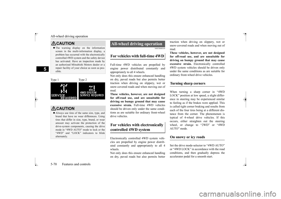
CAUTION The warning display on the information screen in the multi-information display, a problem has occurred with the electronically controlled 4WD system and the safety device has activated. Have an inspection made byan authorized Mitsubishi Motors dealer or a repair facility of your choice as soon as pos- sible.
Type 1 Type 2
CAUTION Always use tires of the same size, type, and brand that have no wear differences. Using tires that differ in size, type, brand, or wear amount may activate the protection of thedrive-system components, causing the drive mode in “4WD AUTO” mode to lock or the “4WD” and “LOCK” indicators to blinkalternately.
All-wheel driving operation For vehicles with full-time 4WD For vehicles with electronically controlled 4WD system
Turning sharp corners On snowy or icy roads
BK0237700US.bo
ok 70 ページ 2016年4月15日 金曜日 午前11時28分