hazard relay MITSUBISHI MONTERO 1987 1.G Workshop Manual
[x] Cancel search | Manufacturer: MITSUBISHI, Model Year: 1987, Model line: MONTERO, Model: MITSUBISHI MONTERO 1987 1.GPages: 284, PDF Size: 14.74 MB
Page 21 of 284
8-1
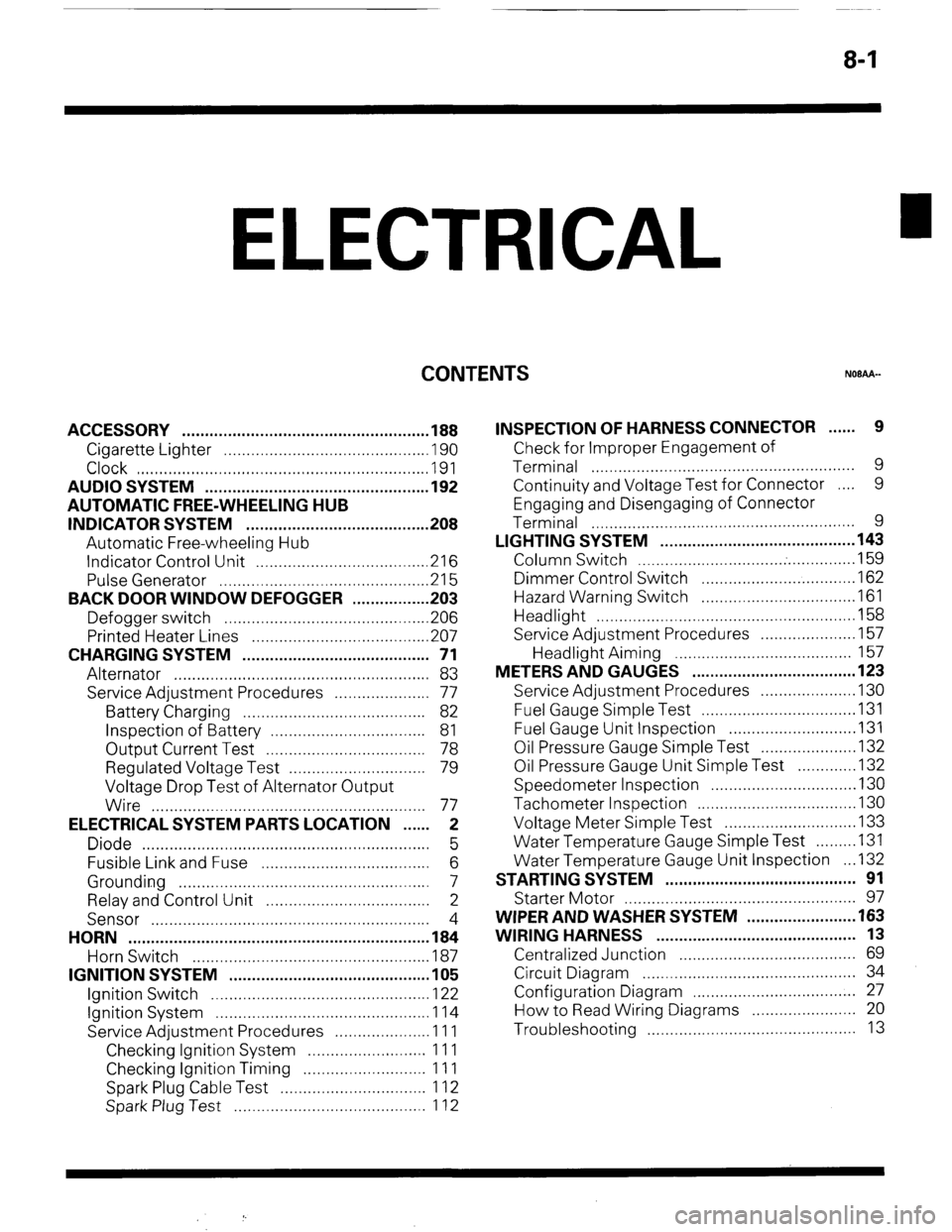
ELECTRICAL
CONTENTS
NOBAA-
ACCESSORY ......................................................
188
Cigarette Lighter ............................................
,190
Clock ...............................................................
,191
AUDIO SYSTEM ................................................
.192
AUTOMATIC FREE-WHEELING HUB
INDICATOR SYSTEM ........................................
208
Automatic Free-wheeling Hub
Indicator Control Unit
..................................... ,216
Pulse Generator ..............................................
215
BACK DOOR WINDOW DEFOGGER
................ .203
Defogger switch ............................................
,206
Printed Heater Lines
...................................... ,207
CHARGING SYSTEM .........................................
71
Alternator ........................................................
83
Service Adjustment Procedures
..................... 77
Battery Charging ........................................
82
Inspection of Battery ..................................
81
Output Current Test ...................................
78
Regulated Voltage Test ..............................
79
Voltage Drop Test of Alternator Output
Wire ............................................................
77
ELECTRICAL SYSTEM PARTS LOCATION
...... 2
Diode ...............................................................
5
Fusible Link and Fuse
..................................... 6
Grounding .......................................................
7
Relay and Control Unit ....................................
2
Sensor .............................................................
4
HORN ..................................................................
184
Horn Switch
.................................................... 187
IGNITION SYSTEM ............................................
105
Ignition Switch
................................................ 122
Ignition System ...............................................
1 14
Service Adjustment Procedures
.................... .l 1 1
Checking Ignition System
..........................
11 1
Checking Ignition Timing
...........................
11 1
Spark Plug Cable Test
................................
1 12
Spark Plug Test
.......................................... 1 12 INSPECTION OF HARNESS CONNECTOR ...... 9
Check for Improper Engagement of
Terminal .......................................................... 9
Continuity and Voltage Test for Connector .... 9
Engaging and Disengaging of Connector
Terminal ..........................................................
9
LIGHTING SYSTEM ........................................... 143
Column Switch
................................ .
.............. .I59
Dimmer Control Switch
................................. .I62
Hazard Warning Switch
................................. .I61
Headlight ........................................................ ,158
Service Adjustment Procedures
.................... .I57
Headlight Aiming .......................................
157
METERS AND GAUGES .................................... 123
Service Adjustment Procedures
.................... .I30
Fuel Gauge Simple Test ................................. .I31
Fuel Gauge Unit Inspection ........................... .I31
Oil Pressure Gauge Simple Test
.................... .I32
Oil Pressure Gauge Unit Simple Test
............ ,132
Speedometer Inspection
............................... .I30
Tachometer Inspection .................................. ,130
Voltage Meter Simple Test
............................ .I33
Water Temperature Gauge Simple Test
....... ..I3 1
Water Temperature Gauge Unit Inspection
. ..I3 2
STARTING SYSTEM .......................................... 91
Starter Motor ............ ....................................... 97
WIPER AND WASHER SYSTEM
....................... .163
WIRING HARNESS ............................................ 13
Centralized Junction ....................................... 69
Circuit Diagram ............................................... 34
Configuration Diagram .................................... 27
How to Read Wiring Diagrams ....................... 20
Troubleshooting .............................................. 13
Page 22 of 284
8-2 ELECTRICAL SYSTEM PARTS LOCATION - Relay and Control Unit
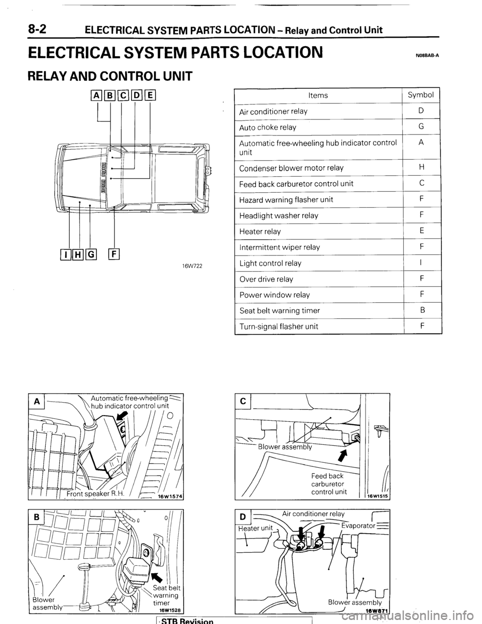
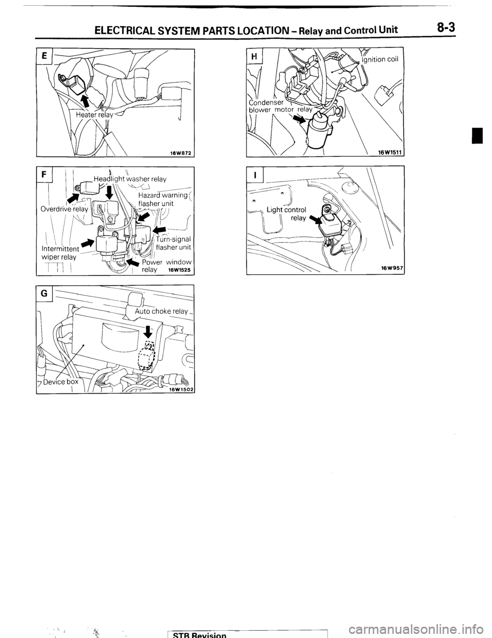
ELECTRICAL SYSTEM IPARTS LOCATION NOIBAB-A
RELAY AND CONTROL UNIT
16W722
n 17
hub indicator control unit A A Automatic free-wheeling 2
Blower
assembiy& x v/i 16W152B Items Symbol
--
Air conditioner relay D
--
Auto choke relay G
--
Automatic free-wheeling hub indicator control
A
unit
Condenser blower motor relay H
Feed back carburetor control unit C
Hazard warning flasher unit F
Headlight washer relay F
Heater relay E
Intermittent wiper relay F
~___
Light control relay I
~___
Over drive relay F
Power window relay F
Seat belt warning timer B
Turn-signal flasher unit F
carburetor
control unit
Air conditioner relay
d--- I- Jr Evaporator E
1 .STB Re\iision
Page 23 of 284
ELECTRICAL SYSTEM PARTS LOCATION - Relay and Control Unit 8-3
FI)I h” -Headlight washer relay
k\\ Hazard warnina f
1 STB Revision
Page 53 of 284
WIRING HARNESS - Instrument Panel 8-33
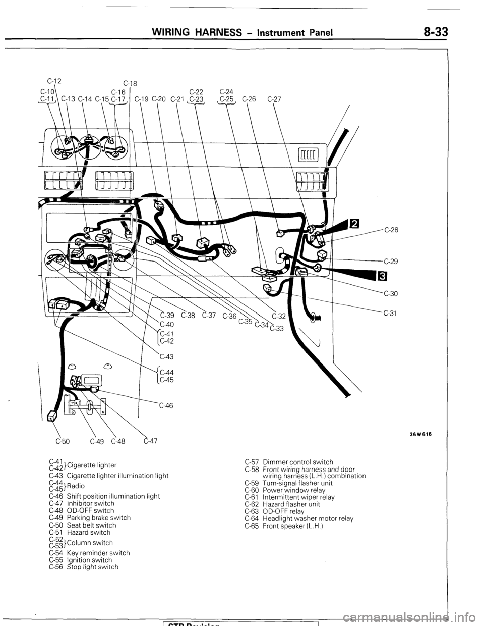
cy50 C149 Cl48 c-47
El$,}Cigarette lightet
C-43 Cigarette lighter illumination light
E::$ Radio
C-46 Shift position illumination light
C-47 Inhibitor switch
C-48 OD-OFF switch
C-49 Parking brake switch
C-50 Seat belt switch
C-51 Hazard switch
E3 Column switch
C-54 Key reminder switch
C-55 Ignition switch
C-56 Stop light switch C-57 Dimmer control switch
C-58 Front wiring harness and door
wiring harness (L.H.) combination
C-59 Turn-signal flasher unit
C-60 Power window relay
C-61 Intermittent wiper relay
C-62 Hazard flasher unit
C-63 OD-OFF relay
C-64 Headlight washer motor relay
C-65 Front speaker (L.H.)
Ision
Page 82 of 284
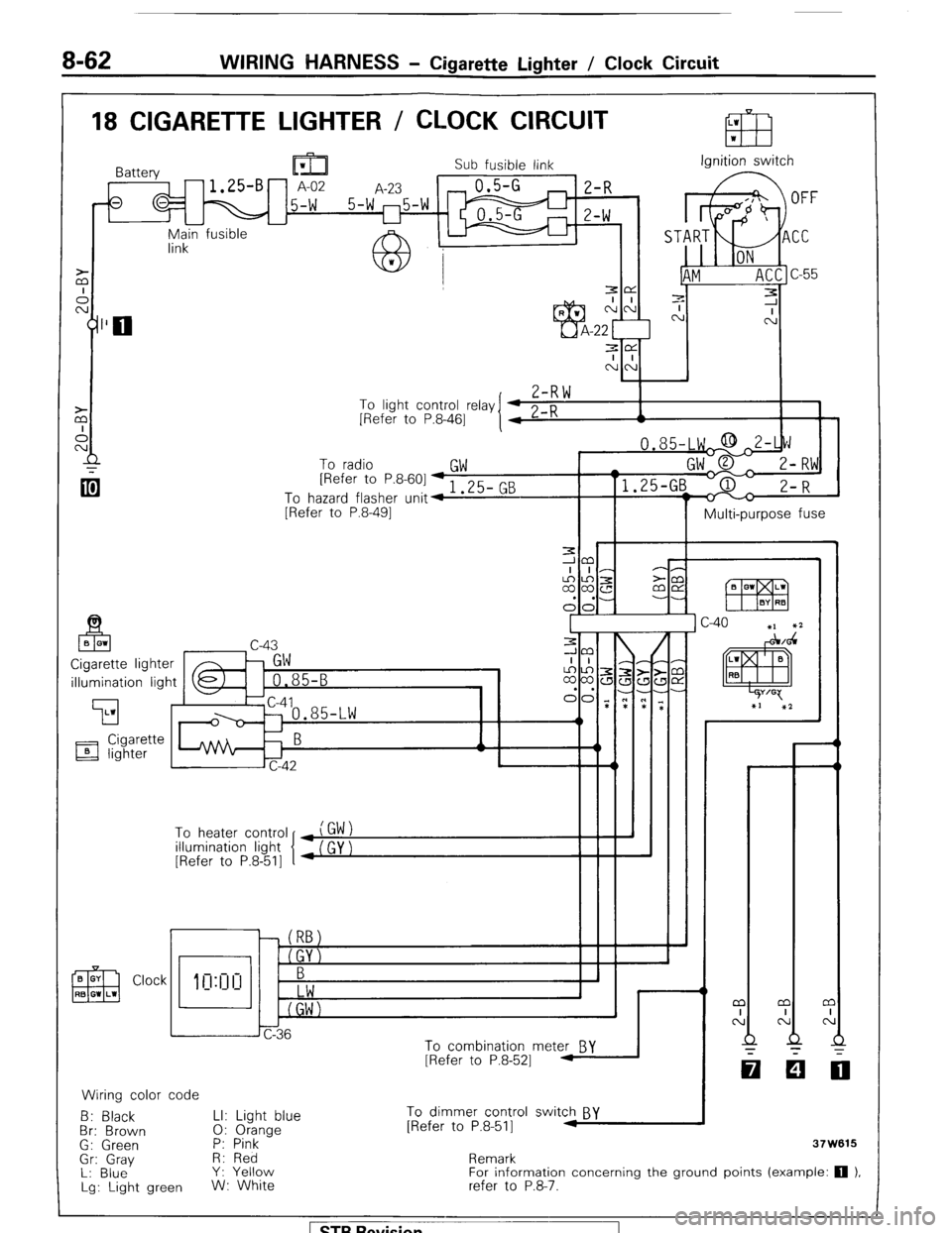
8-62 WIRING HARNESS - Cigarette Lighter / Clock Circuit
18 CIGARETTE LIGHTER / CLOCK CIRCUIT
Sub fusible link Ignition switch
r-l E-f? ‘) n
-u yn;in fusible
7-R \*I
To light control relay
[Refer to P.8-461
To radio
GW [Refer to P&601-, 3F- Pm
To hazard flasher unit4 I .LJ- G
[Refer to P.8-491
II I Multi-purpose fuse
illumination light
To heater control
illumination light
[Refer to P.8-511
Clock
CT
0: 1
h J
6
Jc-36
To combination mete& BY
[Refer to P.8-521 1
Wiring color code
B: Black LI: Light blue To dimmer control switch BY
Br: Brown 0: Orange [Refer to P.8-511 M
G: Green P: Pink
-
Gr: Gray H: Red
L: Blue Y: Yellow
Lg: Light green W: White Remark
For information concerning the ground points (example: 0 1,
refer to P.8-‘7.
Page 90 of 284
WIRING HARNESS - Centralized Junction
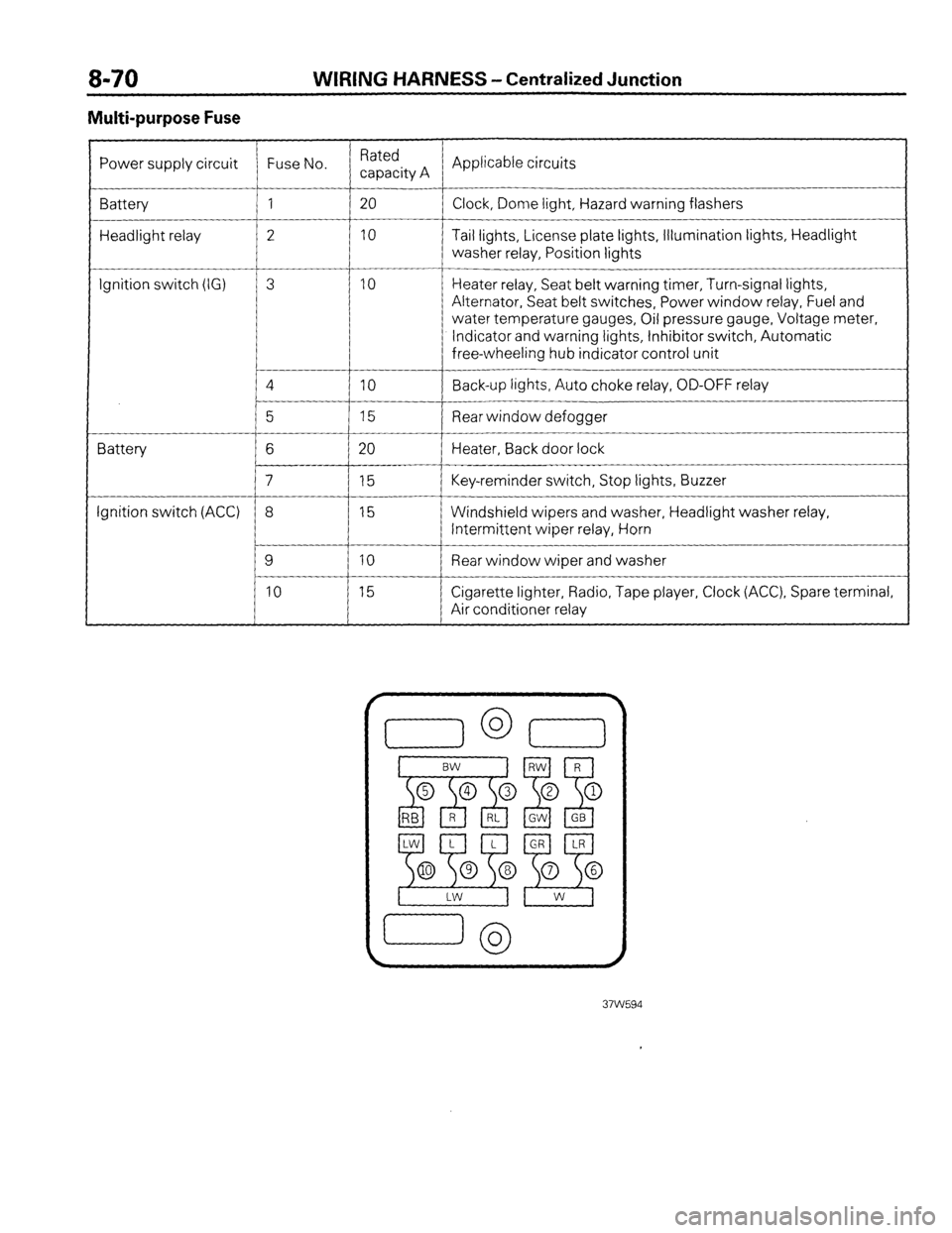
Multi-purpose Fuse
Power supply circuit Fuse No. Rated
capacity A Applicable circuits
Battery 1 20
Clock, Dome light, Hazard warning flashers
Headlight relay 2 10 Tail lights, License plate lights, Illumination lights, Headlight
washer relay, Position lights
__-
Ignition switch (IG) 3 10 Heater relay, Seat belt warning timer, Turn-signal lights,
Alternator, Seat belt switches, Power window relay, Fuel and
water temperature gauges, Oil pressure gauge, Voltage meter,
Indicator and warning lights, Inhibitor switch, Automatic
free-wheeling hub indicator control unit
4
IO Back-up lights, Auto choke relay, OD-OFF relay
__-
5 15 Rear window defogger
Battery 6 20 Heater, Back door lock
7 15 Key-reminder switch, Stop lights, Buzzer
Ignition switch (ACC) 8 15 Windshield wipers and washer, Headlight washer relay,
Intermittent wiper relay, Horn
9 10 Rear window wiper and washer
10 15 Cigarette lighter, Radio, Tape player, Clock (ACC), Spare terminal,
Air conditioner relay
Page 163 of 284
LIGHTING SYSTEM - Specifications 8-143
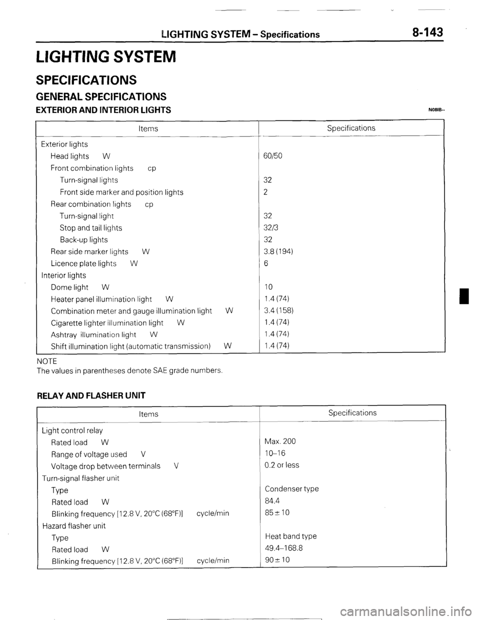
LIGHTING SYSTEM
SPECIFICATIONS
GENERAL SPECIFICATIONS
EXTERIOR AND INTERIOR LIGHTS NOEIB-
Items
Exterior lights
Head lights W
Front combination lights cp
Turn-signal lights
Front side marker and position lights
Rear combination lights cp
Turn-signal light
Stop and tail lights
Back-up lights
Rear side marker lights W
Licence plate lights W
Interior lights
Dome light W
Heater panel illumination light W
Combination meter and gauge illumination light
Cigarette lighter illumination light
W
Ashtray illumination light
W
Shift illumination light (automatic transmission) W
W
NOTE
The values in parentheses denote SAE grade numbers.
RELAY AND FLASHER UNIT
Items
Light control relay
Rated load W
Range of voltage used V
Voltage drop between terminals V
Turn-signal flasher unit
Type
Rated load W
Blinking frequency [I 2.8 V, 20°C (68”F)l
Hazard flasher unit
Type cycle/min
Rated load W
Blinking frequency [ 12.8 V, 20°C (68”F)l cycle/min Specifications
60/50
32
2
32
32/3
32
3.8(194)
6
10 1.4 (74)
3.4 (158)
1.4 (74)
1.4 (74)
1.4 (74)
Specifications
Max. 200
IO-16
0.2 or less
Condenser type
84.4
85210
Heat band type
49.4-168.8
902 10
1 STB Revision