MITSUBISHI MONTERO 1998 Service Manual
Manufacturer: MITSUBISHI, Model Year: 1998, Model line: MONTERO, Model: MITSUBISHI MONTERO 1998Pages: 1501, PDF Size: 25.81 MB
Page 551 of 1501
NOTE: Always refer to appropriate engine overhaul article in the
ENGINES section for complete overhaul procedures and
specifications for the vehicle being repaired.
REMOVAL
Remove intake and exhaust manifolds and valve cover. Cylinder
head and camshaft carrier bolts (if equipped), should be removed only
when the engine is cold. On many aluminum cylinder heads, removal
while hot will cause cylinder head warpage. Mark rocker arm or
overhead cam components for location.
Remove rocker arm components or overhead cam components.
Components must be installed in original location. Individual design
rocker arms may utilize shafts, ball-type pedestal mounts or no rocker
arms. For all design types, wire components together and identify
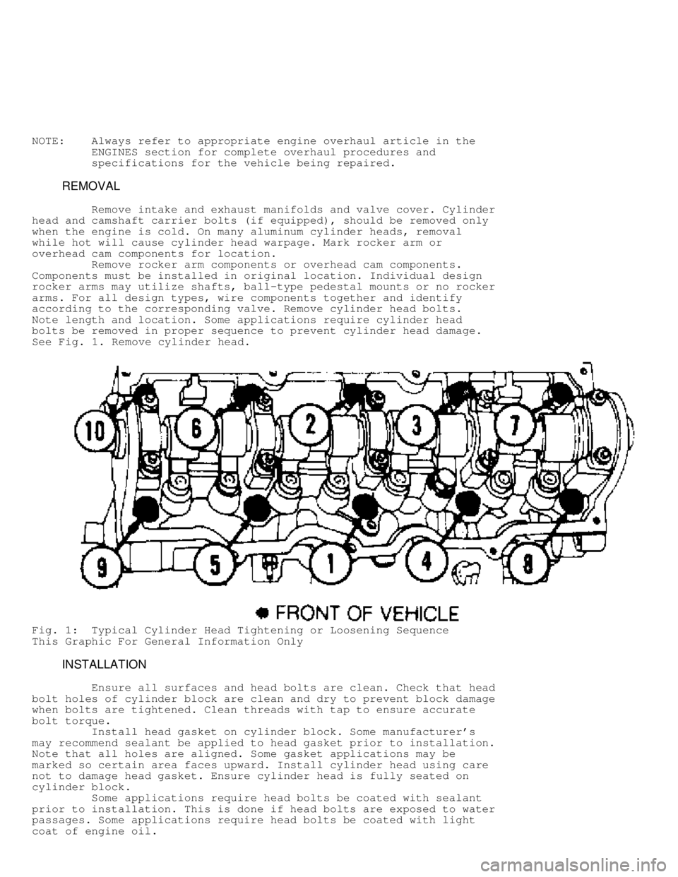
according to the corresponding valve. Remove cylinder head bolts.
Note length and location. Some applications require cylinder head
bolts be removed in proper sequence to prevent cylinder head damage.
See Fig. 1 . Remove cylinder head.
Fig. 1: Typical Cylinder Head Tightening or Loosening Sequence
This Graphic For General Information Only
INSTALLATION
Ensure all surfaces and head bolts are clean. Check that head
bolt holes of cylinder block are clean and dry to prevent block damage
when bolts are tightened. Clean threads with tap to ensure accurate
bolt torque.
Install head gasket on cylinder block. Some manufacturer's
may recommend sealant be applied to head gasket prior to installation.
Note that all holes are aligned. Some gasket applications may be
marked so certain area faces upward. Install cylinder head using care
not to damage head gasket. Ensure cylinder head is fully seated on
cylinder block.
Some applications require head bolts be coated with sealant
prior to installation. This is done if head bolts are exposed to water
passages. Some applications require head bolts be coated with light
coat of engine oil.
Page 552 of 1501

Install head bolts. Head bolts should be tightened in proper
steps and sequence to specification. See Fig. 1. Install remaining
components. Tighten all bolts to specification. Adjust valves if
required. See VALVE ADJUSTMENT in this article.
NOTE: Some manufacturers require that head bolts be retightened
after specified amount of operation. This must be done to
prevent head gasket failure.
VALVE ADJUSTMENT
Engine specifications will indicate valve train clearance and
temperature at which adjustment is to be made on most models. In most
cases, adjustment will be made with a cold engine. In some cases, both
a cold and a hot clearance will be given for maintenance convenience.
On some models, adjustment is not required. Rocker arms are
tightened to specification and valve lash is automatically set. On
some models with push rod actuated valve train, adjustment is made at
push rod end of rocker arm while other models do not require
adjustment.
Clearance will be checked between tip of rocker arm and tip
of valve stem in proper sequence using a feeler gauge. Adjustment is
made by rotating adjusting screw until proper clearance is obtained.
Lock nut is then tightened. Engine will be rotated to obtain all valve
adjustments to manufacturer's specifications.
Some models require hydraulic lifter to be bled down and
clearance measured. Different length push rods can be used to obtain
proper clearance. Clearance will be checked between tip of rocker arm
and tip of valve stem in proper sequence using a feeler gauge.
On overhead cam engines designed without rocker arms actuate
valves directly on a cam follower. A hardened, removable disc is
installed between the cam lobe and lifter. Clearance will be checked
between cam heel and adjusting disc in proper sequence using a feeler
gauge. Engine will be rotated to obtain all valve adjustments.
On overhead cam engines designed with rocker arms, adjustment
is made at push rod end of rocker arm. Ensure that the valve to be
adjusted is riding on the heel of the cam on all engines. Clearance
will be checked between tip of rocker arm and tip of valve stem in
proper sequence using a feeler gauge. Adjustment is made by rotating
adjusting screw until proper clearance is obtained. Lock nut is then
tightened. Engine will be rotated to obtain all valve adjustments to
manufacturer's specifications.
CYLINDER HEAD OVERHAUL
* PLEASE READ THIS FIRST *
NOTE: Always refer to appropriate engine overhaul article in the
ENGINES section for complete overhaul procedures and
specifications for the vehicle being repaired.
DISASSEMBLY
Mark valves for location. Using valve spring compressor,
compress valve springs. Remove valve locks. Carefully release spring
compressor. Remove retainer or rotator, valve spring, spring seat and
valve. See Fig. 2.
Page 553 of 1501
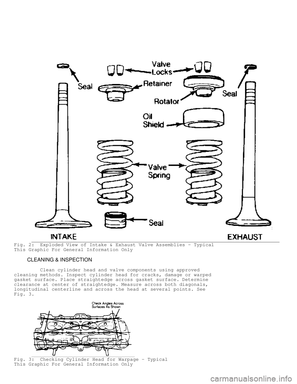
Fig. 2: Exploded View of Intake & Exhaust Valve Assemblies - Typical
This Graphic For General Information Only
CLEANING & INSPECTION
Clean cylinder head and valve components using approved
cleaning methods. Inspect cylinder head for cracks, damage or warped
gasket surface. Place straightedge across gasket surface. Determine
clearance at center of straightedge. Measure across both diagonals,
longitudinal centerline and across the head at several points. See
Fig. 3 .
Fig. 3: Checking Cylinder Head for Warpage - Typical
This Graphic For General Information Only
Page 554 of 1501
On cast cylinder heads, if warpage exceeds .003" (.08 mm)
in a 6" span, or .006" (.15 mm) over total length, cylinder head must
be resurfaced. On most aluminum cylinder heads, if warpage exceeds .
002" (.05 mm) in any area, cylinder head must be resurfaced. Warpage
specification may vary with manufacturer.
Cylinder head thickness should be measured to determine
amount of material which can be removed before replacement is
required. Cylinder head thickness must not be less than manufacturer's
specifications.
If cylinder head required resurfacing, it may not align
properly with intake manifold. On "V" type engines, misalignment is
corrected by machining intake manifold surface that contacts cylinder
head. Cylinder head may be machined on surface that contacts intake
manifold.
Using oil stone, remove burrs or scratches from all sealing
surfaces.
VALVE SPRINGS
Inspect valve springs for corroded or pitted valve spring
surfaces which may lead to breakage. Polished spring ends caused by
a rotating spring, indicates that spring surge has occurred. Replace
springs showing evidence of these conditions.
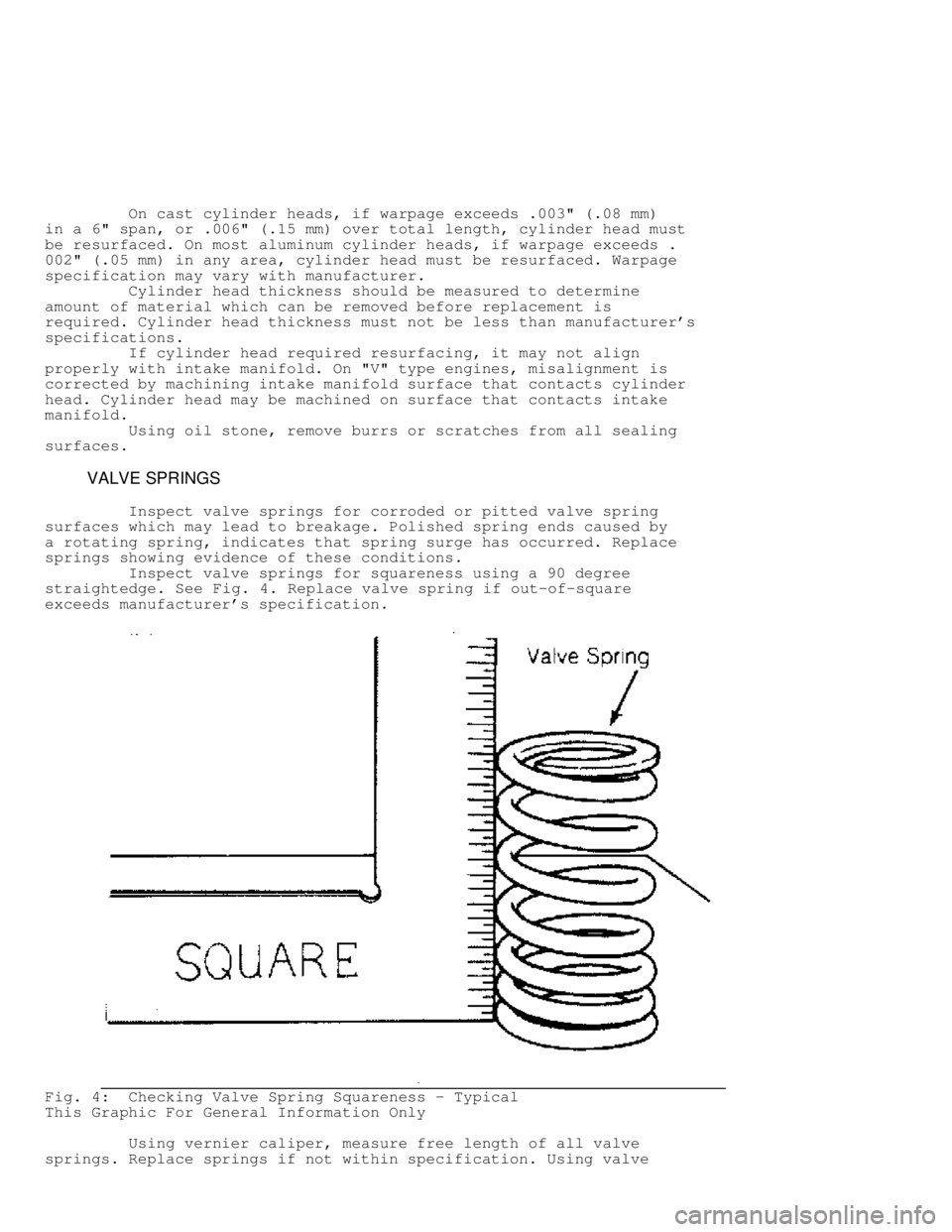
Inspect valve springs for squareness using a 90 degree
straightedge. See Fig. 4. Replace valve spring if out-of-square
exceeds manufacturer's specification.
Fig. 4: Checking Valve Spring Squareness - Typical
This Graphic For General Information Only
Using vernier caliper, measure free length of all valve
springs. Replace springs if not within specification. Using valve
Page 555 of 1501
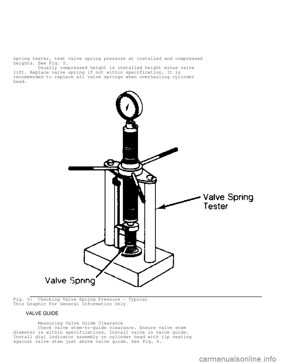
spring tester, test valve spring pressure at installed and compressed
heights. See Fig. 5.
Usually compressed height is installed height minus valve
lift. Replace valve spring if not within specification. It is
recommended to replace all valve springs when overhauling cylinder
head.
Fig. 5: Checking Valve Spring Pressure - Typical
This Graphic For General Information Only
VALVE GUIDE
Measuring Valve Guide Clearance
Check valve stem-to-guide clearance. Ensure valve stem
diameter is within specifications. Install valve in valve guide.
Install dial indicator assembly on cylinder head with tip resting
against valve stem just above valve guide. See Fig. 6.
Page 556 of 1501
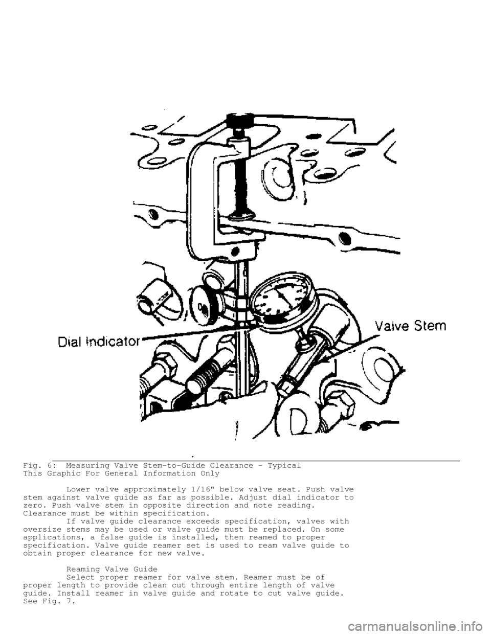
Fig. 6: Measuring Valve Stem-to-Guide Clearance - Typical
This Graphic For General Information Only
Lower valve approximately 1/16" below valve seat. Push valve
stem against valve guide as far as possible. Adjust dial indicator to
zero. Push valve stem in opposite direction and note reading.
Clearance must be within specification.
If valve guide clearance exceeds specification, valves with
oversize stems may be used or valve guide must be replaced. On some
applications, a false guide is installed, then reamed to proper
specification. Valve guide reamer set is used to ream valve guide to
obtain proper clearance for new valve.
Reaming Valve Guide
Select proper reamer for valve stem. Reamer must be of
proper length to provide clean cut through entire length of valve
guide. Install reamer in valve guide and rotate to cut valve guide.
See Fig. 7 .
Page 557 of 1501
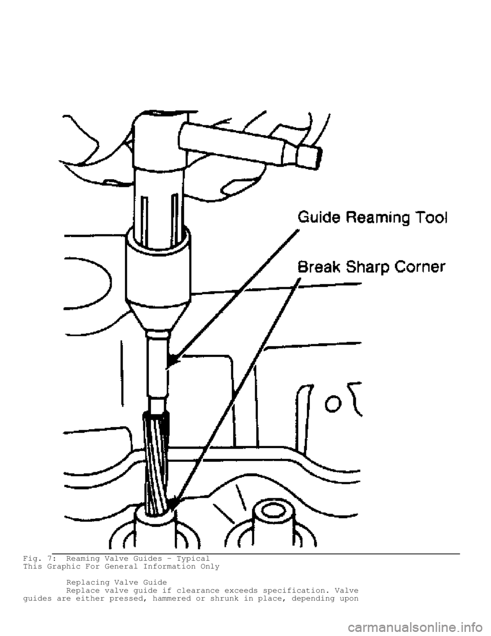
Fig. 7: Reaming Valve Guides - Typical
This Graphic For General Information Only
Replacing Valve Guide
Replace valve guide if clearance exceeds specification. Valve
guides are either pressed, hammered or shrunk in place, depending upon
Page 558 of 1501
cylinder head design and type of metal used.
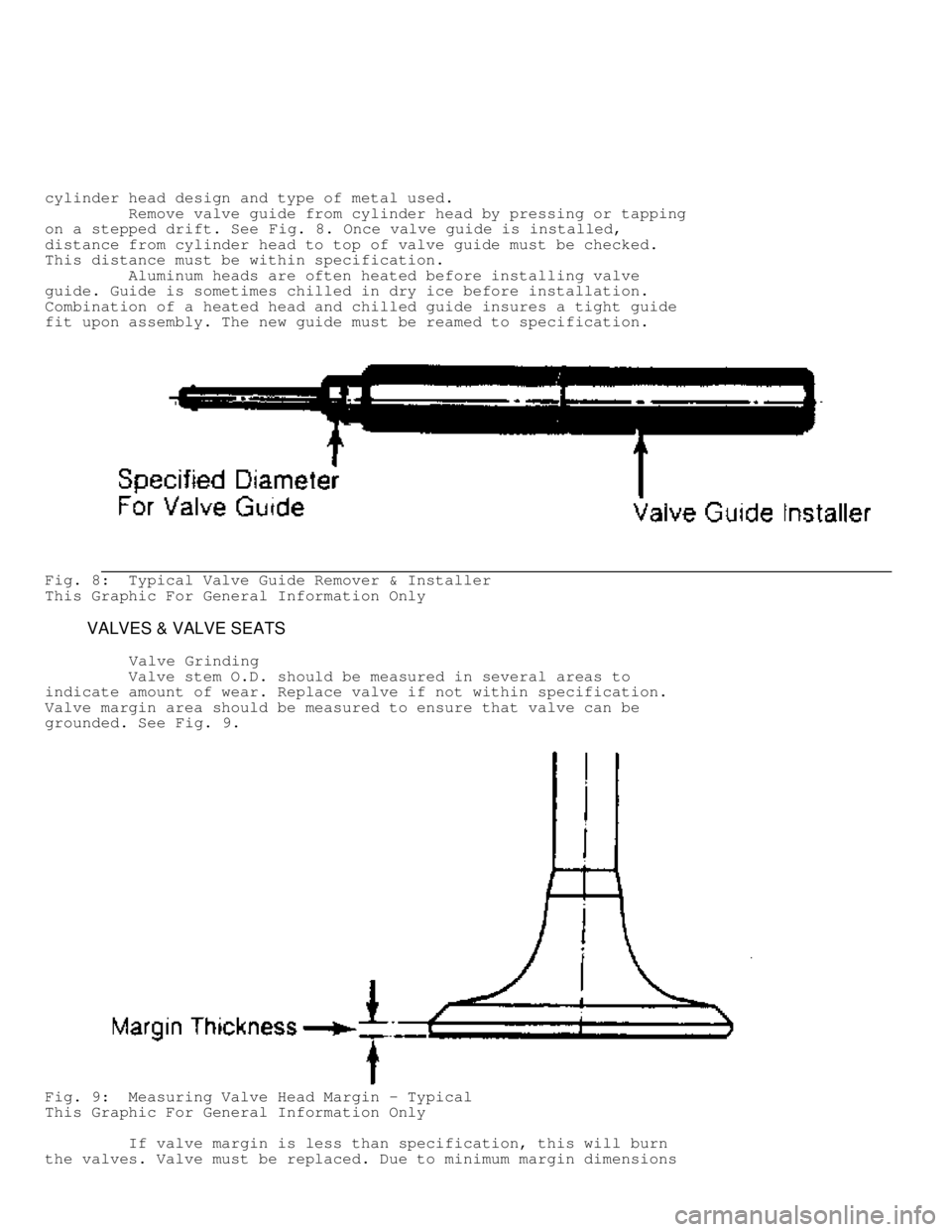
Remove valve guide from cylinder head by pressing or tapping
on a stepped drift. See Fig. 8. Once valve guide is installed,
distance from cylinder head to top of valve guide must be checked.
This distance must be within specification.
Aluminum heads are often heated before installing valve
guide. Guide is sometimes chilled in dry ice before installation.
Combination of a heated head and chilled guide insures a tight guide
fit upon assembly. The new guide must be reamed to specification.
Fig. 8: Typical Valve Guide Remover & Installer
This Graphic For General Information Only
VALVES & VALVE SEATS
Valve Grinding
Valve stem O.D. should be measured in several areas to
indicate amount of wear. Replace valve if not within specification.
Valve margin area should be measured to ensure that valve can be
grounded. See Fig. 9.
Fig. 9: Measuring Valve Head Margin - Typical
This Graphic For General Information Only
If valve margin is less than specification, this will burn
the valves. Valve must be replaced. Due to minimum margin dimensions
Page 559 of 1501
during manufacture, some new type valves cannot be reground.
Resurface valve on proper angle specification using valve
grinding machine. Follow manufacturer's instructions for valve
grinding machine. Specifications may indicate a different valve face
angle than seat angle.
Measure valve margin after grinding. Replace valve if not
within specification. Valve stem tip can be refinished using valve
grinding machine.
Valve Lapping
During valve lapping of recent designed valves, be sure to
follow manufacturers recommendations. Surface hardening and materials
used with some valves do not permit lapping. Lapping process will
remove excessive amounts of the hardened surface.
Valve lapping is done to ensure adequate sealing between
valve face and seat. Use either a hand drill or lapping stick with
suction cup attached.
Moisten and attach suction cup to valve. Lubricate valve stem
and guide. Apply a thin coat of fine valve grinding compound between
valve and seat. Rotate lapping tool between the palms or with hand
drill.
Lift valve upward off the seat and change position often.
This is done to prevent grooving of valve seat. Lap valve until a
smooth polished seat is obtained. Thoroughly clean grinding compound
from components. Valve to valve seat concentricity should be checked.
See VALVE SEAT CONCENTRICITY.
CAUTION: Valve guides must be in good condition and free of carbon
deposits prior to valve seat grinding. Some engines contain
an induction hardened valve seat. Excessive material removal
will damage valve seats.
Valve Seat Grinding
Select coarse stone of correct size and angle for seat to be
ground. Ensure stone is true and has a smooth surface. Select correct
size pilot for valve guide dimension. Install pilot in valve guide.
Lightly lubricate pilot shaft. Install stone on pilot. Move stone off
and on the seat approximately 2 times per second during grinding
operation.
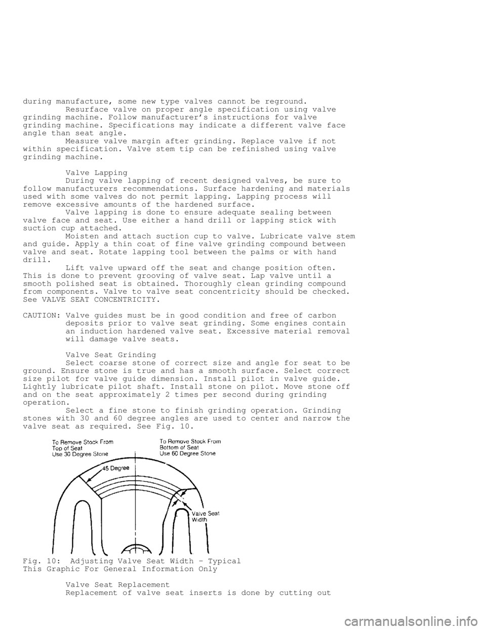
Select a fine stone to finish grinding operation. Grinding
stones with 30 and 60 degree angles are used to center and narrow the
valve seat as required. See Fig. 10.
Fig. 10: Adjusting Valve Seat Width - Typical
This Graphic For General Information Only
Valve Seat Replacement
Replacement of valve seat inserts is done by cutting out
Page 560 of 1501
the old insert and machining an oversize insert bore. Replacement
oversize insert is usually chilled and the cylinder head is sometimes
warmed. Valve seat is pressed into the head. This operation requires
specialized machine shop equipment.
Valve Seat Concentricity
Using dial gauge, install gauge pilot in valve guide.
Position gauge arm on the valve seat. Adjust dial indicator to zero.
Rotate arm 360 degrees and note reading. Runout should not exceed
specification.
To check valve-to-valve seat concentricity, coat valve face
lightly with Prussian Blue dye. Install valve and rotate it on valve
seat. If pattern is even and entire seat is coated at valve contact
point, valve is concentric with the seat.
REASSEMBLY
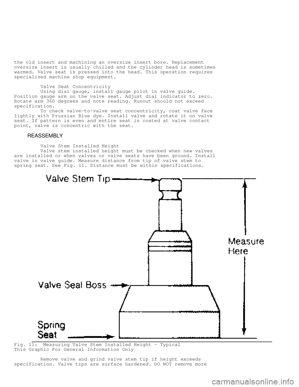
Valve Stem Installed Height
Valve stem installed height must be checked when new valves
are installed or when valves or valve seats have been ground. Install
valve in valve guide. Measure distance from tip of valve stem to
spring seat. See Fig. 11. Distance must be within specifications.
Fig. 11: Measuring Valve Stem Installed Height - Typical
This Graphic For General Information Only
Remove valve and grind valve stem tip if height exceeds
specification. Valve tips are surface hardened. DO NOT remove more