MITSUBISHI SPYDER 1990 Service Repair Manual
Manufacturer: MITSUBISHI, Model Year: 1990, Model line: SPYDER, Model: MITSUBISHI SPYDER 1990Pages: 2103, PDF Size: 68.98 MB
Page 1051 of 2103
![MITSUBISHI SPYDER 1990 Service Repair Manual AUTOMATIC TRANSAXLE
ENGINE (TURBO) AND ENGINE,
INSPECTION PROCEDURE 14
Poor accelerationI
[Comment]l Malfunction of clutches and brakesWhile driving, acceleration is poor even if MITSUBISHI SPYDER 1990 Service Repair Manual AUTOMATIC TRANSAXLE
ENGINE (TURBO) AND ENGINE,
INSPECTION PROCEDURE 14
Poor accelerationI
[Comment]l Malfunction of clutches and brakesWhile driving, acceleration is poor even if](/img/19/57345/w960_57345-1050.png)
AUTOMATIC TRANSAXLE
ENGINE (TURBO) AND ENGINE,
INSPECTION PROCEDURE 14
Poor accelerationI
[Comment]l Malfunction of clutches and brakesWhile driving, acceleration is poor even if downshi fting is performed. In such cases, the causeMalfunction of engine system
is probably a defective clutch or brake, or a defec tive engine system.
Refer to Automatic Transaxle Overhaul
Engine system check
lCheck the control system, ignition system, fuel sys temand main engine system, and confirm that everything
is normal.
lIf there is an abnormality, repair or replace the enginesystem.
After completion
Clutch and brake check
lCheck each end play, and if they exceed the standar d
l Check for burning and wear in each facing.
INSPECTION PROCEDURE 15 ,
l VibrationProbable cause
[Comment] l Abnormal torque converter pressure
Vibration occurs when driving at constant speed or when accelerating in top range. In such l
Malfunction of engine system
cases, the cause is probably abnormal torque conver ter clutch pressure or a defective torque
Malfunction of torque converter converter. o f v a l v e b o d y
Refer to Automatic
sensor connector is disconnected?
No
Yes
Standard value: (64-92 psi)
OK
If it is considered that the damage or chipping can not
be repaired, replace the valve body assembly.
TSB Revision
Page 1052 of 2103
![MITSUBISHI SPYDER 1990 Service Repair Manual AUTOMATIC TRANSAXLE
ENGINE (TURBO) AND ENGINE>
INSPECTION PROCEDURE 16. .
l Overdrive switch system Probable cause .
[Comment]l Malfunction of overdrive switch In cases such as MITSUBISHI SPYDER 1990 Service Repair Manual AUTOMATIC TRANSAXLE
ENGINE (TURBO) AND ENGINE>
INSPECTION PROCEDURE 16. .
l Overdrive switch system Probable cause .
[Comment]l Malfunction of overdrive switch In cases such as](/img/19/57345/w960_57345-1051.png)
AUTOMATIC TRANSAXLE
ENGINE (TURBO) AND ENGINE>
INSPECTION PROCEDURE 16. .
l Overdrive switch system Probable cause .
[Comment]l Malfunction of overdrive switch In cases such as the above, the cause is probably a defective overdrive switch circuit or defectivelMalfunction of ignition switch circuit.
l Malfunction of ignition switch
l Malfunction of TCM
Overdrive switch check to
NG Replace
Measure at overdrive switch connector
lVoltage between terminals (3) and
OK: Battery positive voltage
OK.NG
OK
Repair
Check trouble svmotom.
Check the l
OK
NG Repair
ignition switch and overdrive switch
NG
NG
Repairoverdrive switch and TCM connectors.OK
TSB Revision
the TCM.
. .
INSPECTION PROCEDURE 17
l Closed throttle position switch system
Probable cause
[Comment]In cases such as the above, the cause is probably a defective closed throttle position switchl
Malfunction of closed lcircuit.Malfunction of connector
l Malfunction of
Closed throttle position switch check Replace the position sensor.
(Refer to GROUP On-vehicle
Inspection of Components.)
OK
Check the following connectors:NG Repair
.
OK
Check trouble
NG
Check the harness wire between theN G Repairclosed throttle position switch and TCM
connectors.
OK
Replace the TCM.
Page 1053 of 2103
![MITSUBISHI SPYDER 1990 Service Repair Manual AUTOMATIC TRANSAXLE
ENGINE (TURBO) AND ENGINE> Troubleshooting
INSPECTION PROCEDURE 18l A/C load signal system
[Comment]In cases such as the above, the cause is probably a defe MITSUBISHI SPYDER 1990 Service Repair Manual AUTOMATIC TRANSAXLE
ENGINE (TURBO) AND ENGINE> Troubleshooting
INSPECTION PROCEDURE 18l A/C load signal system
[Comment]In cases such as the above, the cause is probably a defe](/img/19/57345/w960_57345-1052.png)
AUTOMATIC TRANSAXLE
ENGINE (TURBO) AND ENGINE> Troubleshooting
INSPECTION PROCEDURE 18l A/C load signal system
[Comment]In cases such as the above, the cause is probably a defective Idle position switch circuit.
Dual pressure switch check (Refer to
NG Replace
GROUP 55 On-vehicle Service.)
OK
Measure at TCM connector l connector and mea-sure at the harness side.
l Ignition switch: ON
l
switch: ON
lVoltage between terminals (8) and
ground
OK: Battery positive voltage
Check trouble symptom.
NG
P r o b a b l e
system check (Refer to GROUP
55 Troubleshooting.)
Replace the TCM. l
Malfunction of dual pressure
l Malfunction of l Malfunction of A/C system
l Malfunction of TCM
Check the following connectors:
TSB Revision. .
Page 1054 of 2103
![MITSUBISHI SPYDER 1990 Service Repair Manual AUTOMATIC TRANSAXLE .
ENGINE (TURBO) AND
INSPECTION PROCEDURE
l Vehicle speed sensor systemProbable ‘cause
[Comment]l Malfunction of vehicle speed In cases such as the above, the MITSUBISHI SPYDER 1990 Service Repair Manual AUTOMATIC TRANSAXLE .
ENGINE (TURBO) AND
INSPECTION PROCEDURE
l Vehicle speed sensor systemProbable ‘cause
[Comment]l Malfunction of vehicle speed In cases such as the above, the](/img/19/57345/w960_57345-1053.png)
AUTOMATIC TRANSAXLE .
ENGINE (TURBO) AND
INSPECTION PROCEDURE
l Vehicle speed sensor systemProbable ‘cause
[Comment]l Malfunction of vehicle speed In cases such as the above, the cause, is probably a defective vehicle speed sensor circuit.
Malfunction of connectorl.
l
of TCM
(Refer to
N G Replace
. .. .
Measure at the vehicle speed 1. NGNG Check the following con-, RepairlDisconnect the connector, and measure at the harnes s side.1. Voltage between 1 and ground
(Ignition switch: ON)
OK: Battery positive voltage
2. Voltage between 3 and ground (Ignition switch: ON)
O K :
2. NG
3. Continuity between 2 and ground O K :
NGCheck the following con-+ Repair
OK
Check trouble symptom.
OK
Replace the TCM.
OK
Check trouble symptom..I
NG
Check the ignition switch.
(Refer to GROUP 54 switch)
NGCheck the following con- +.
OK
Check trouble symptom.
NG
NG
Check the harness wirebetween the TCM and thev e h i c l e s e n s o r connector.’
the TCM.
Repair
I
Check the harness wire between the vehicle speed se nsor and
the ground and repair if necessary.
TSB Revision
Page 1055 of 2103
AUTOMATIC TRANSAXLE
ENGINE (TURBO) AND ENGINE> Troubleshooting
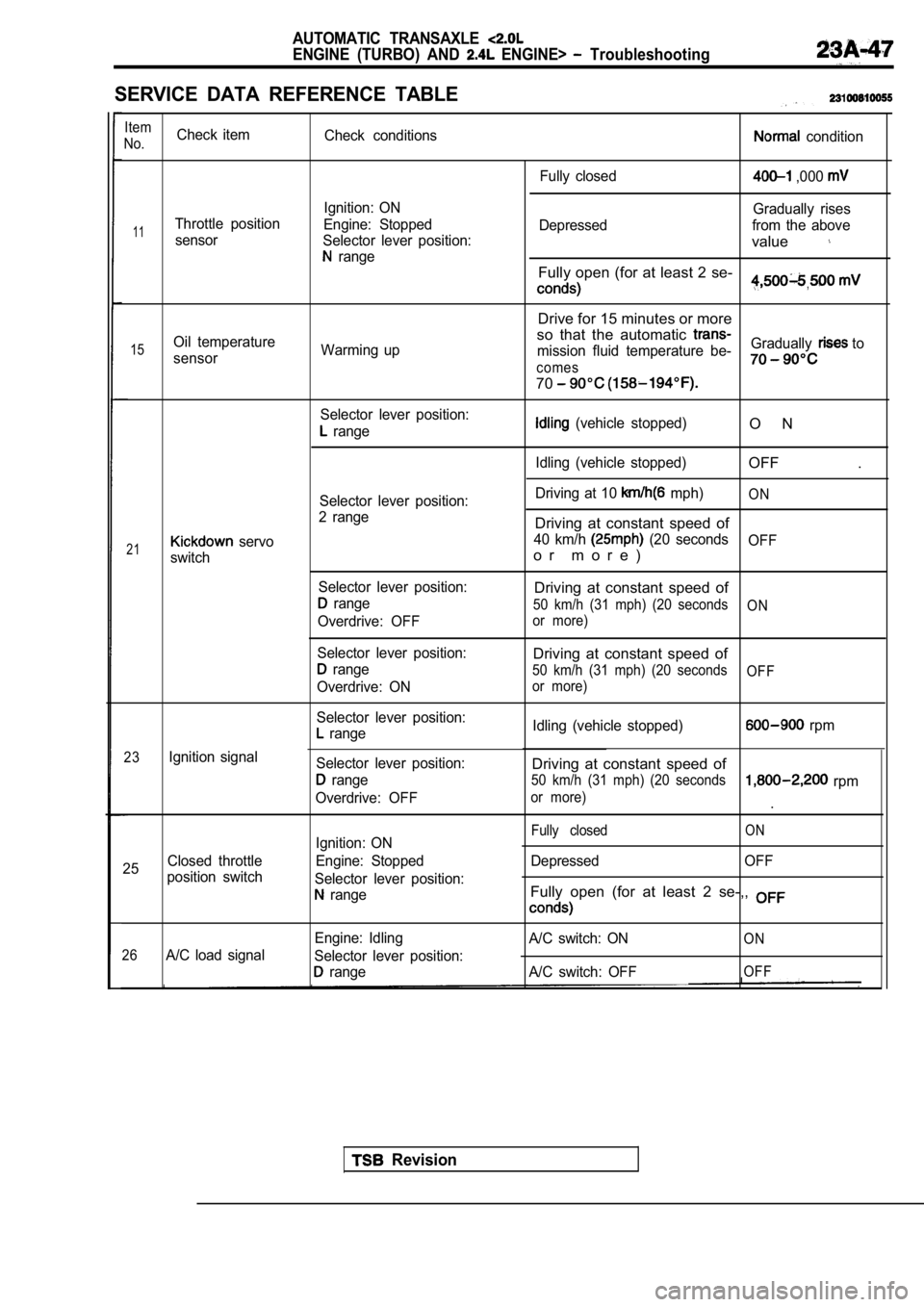
SERVICE DATA REFERENCE TABLE
Item
No.Check item Check conditions condition
Fully closed
,000
Ignition: ON Gradually rises
11Throttle positionEngine: Stopped Depressed from the above
sensor Selector lever position:
value range
Fully open (for at least 2 se-,
Drive for 15 minutes or more
so that the automatic
15Oil temperature Warming up mission fluid temperature be-Gradually to
sensor
comes
70
Selector lever position:
range (vehicle stopped)
Idling (vehicle stopped)O N
OFF .
21
23
25
servo
switch
Ignition signal
Closed throttle
position switch Selector lever position:
2 range
Selector lever position:
range
Overdrive: OFF
Selector lever position:
range
Overdrive: ON
Selector lever position:
range
Selector lever position:
range
Overdrive: OFF
Ignition: ON
Engine: Stopped
Selector lever position:
range Driving at 10
mph)ON
Driving at constant speed of
40 km/h (20 seconds
OFF
o r m o r e )
Driving at constant speed of
50 km/h (31 mph) (20 seconds ON
or more)
Driving at constant speed of
50 km/h (31 mph) (20 seconds OFF
or more)
Idling (vehicle stopped) rpm
Driving at constant speed of
50 km/h (31 mph) (20 seconds rpm
or more).
O NFully closed
Depressed OFF
Fully open (for at least 2 se-,,
26A/C load signal Engine: Idling
Selector lever position:
range A/C switch: ON
A/C switch: OFF
ON
OFF
Revision
Page 1056 of 2103
AUTOMATIC TRANSAXLE
ENGINE (TURBO) AND ENGINE> Troubleshooting
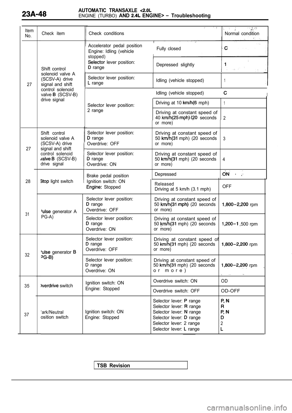
Item
No.
27
27
28
31
32
35
37 Check item
Shift control
solenoid valve A
(SCSV-A) drive
signal and shift
control solenoid
valve
(SCSV-B)
drive signal
Shift control
solenoid valve A
(SCSV-A) drive
signal and shift
control solenoid
(SCSV-B)
drive signal
Ignition switch: ON
Stopped
Selector lever position:
range
Overdrive: OFF
Selector lever position:
range
Overdrive: ON
Brake pedal position
light switch
Check conditionsNormal condition
Fully closed
Accelerator pedal position
Engine: Idling (vehicle
stopped)
lever position:
range Depressed slightly
Selector lever position:
range Idling (vehicle stopped)1
Idling (vehicle stopped)I
Selector lever position:
2 range Driving at 10 mph)1
Driving at constant speed of
40 seconds2or more)
Released
Driving at 5 km/h (3.1 mph)
Driving at constant speed of
50 mph) (20 seconds3
or more)
Driving at constant speed of
50 mph) (20 seconds4
or more)
Depressed ,
OFF
Selector lever position:
Driving at constant speed of
range 50 (20 seconds rpm
generator AOverdrive: OFFor more)
PG-A)
Selector lever position:Driving at constant speed of range 50 mph) (20 seconds ,500 rpm
Overdrive: ON
or more)
Selector lever position:Driving at constant speed of range 50 mph) (20 seconds rpm
generator Overdrive: OFFor more)
Selector lever position:Driving at constant speed of range50 mph) (20 seconds rpm
Overdrive: ONo r m o r e )
Ignition switch: ON Overdrive switch: ONOD switchEngine: Stopped
Overdrive switch: OFFOD-OFF
Selector lever: range
Selector lever: range
‘ark/NeutralIgnition switch: ON Selector lever: range
osition switchEngine: Stopped Selector lever: range
Selector lever: 2 range2
Selector lever: range
TSB Revision
Page 1057 of 2103
AUTOMATIC TRANSAXLE
ENGINE (TURBO) AND ENGINE> Troubleshooting
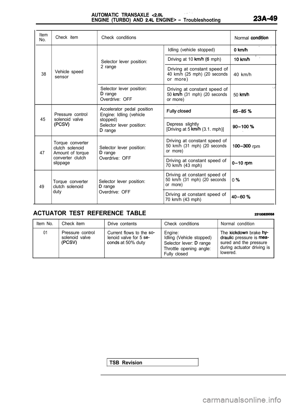
Item
No. Check itemCheck conditions
Normal
Idling (vehicle stopped)
Driving at 10 mph)Selector lever position:
2 range
Vehicle speedDriving at constant speed of
38 40 km/h (25 mph) (20 seconds40 km/hsensoro r m o r e )
Selector lever position:Driving at constant speed of range50 (31 mph) (20 seconds50Overdrive: OFF
or more)
Accelerator pedal position
Pressure control Engine: Idling (vehicle
45solenoid valvestopped)
Selector lever position: Depress slightly
range[Driving at 5 (3.1. mph)]
47
49
Torque converter
clutch solenoid
Amount of torque
converter clutch
slippage
Torque converter
clutch solenoid
duty Selector lever position:
range
Overdrive: OFF
Selector lever position:
range
Overdrive: OFF
Driving at constant speed of
50 km/h (31 mph) (20 seconds rpmor more)
Driving at constant speed of
70 km/h (43 mph)
Driving at constant speed of
50 km/h (31 mph) (20 seconds0or more)
Driving at constant speed of
70 km/h (43 mph)0
ACTUATOR TEST REFERENCE TABLE
Item No.Check item Drive contents
01Pressure controlCurrent flows to the
solenoid valve lenoid valve for 5
at 50% duty
Check conditions
Engine:
Idling (Vehicle stopped)
Selector lever:
range
Throttle opening angle: Fully closed
Normal condition
The brake
pressure is
sured and the pressure
during actuator driving is
lowered.
TSB Revision
Page 1058 of 2103
AUTOMATIC TRANSAXLE
ENGINE AND ENGINE> Troubleshootina
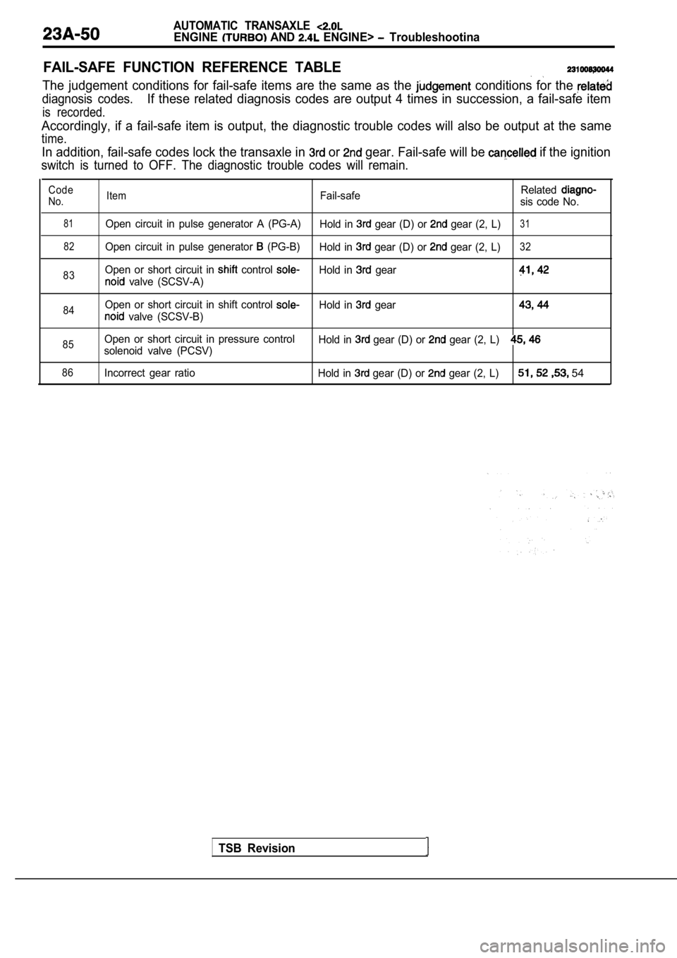
FAIL-SAFE FUNCTION REFERENCE TABLE
The judgement conditions for fail-safe items are the same as the conditions for the
diagnosis codes.If these related diagnosis codes are output 4 times in succession, a fail-safe item
is recorded.
Accordingly, if a fail-safe item is output, the diagnostic trouble codes will also be output at the sa me
time.
In addition, fail-safe codes lock the transaxle in or gear. Fail-safe will be if the ignition
switch is turned to OFF. The diagnostic trouble cod es will remain.
Code
No.ItemFail-safe Relatedsis code No.
81
82
83
Open circuit in pulse generator A (PG-A)
Hold in gear (D) or gear (2, L)31
Open circuit in pulse generator (PG-B)Hold in gear (D) or gear (2, L)32
Open or short circuit in control Hold in gear
valve (SCSV-A)
84Open or short circuit in shift control Hold in gear
valve (SCSV-B)
85Open or short circuit in pressure control
solenoid valve (PCSV) Hold in gear (D) or gear (2, L)
86Incorrect gear ratio
Hold in gear (D) or gear (2, L) 54
TSB Revision
Page 1059 of 2103
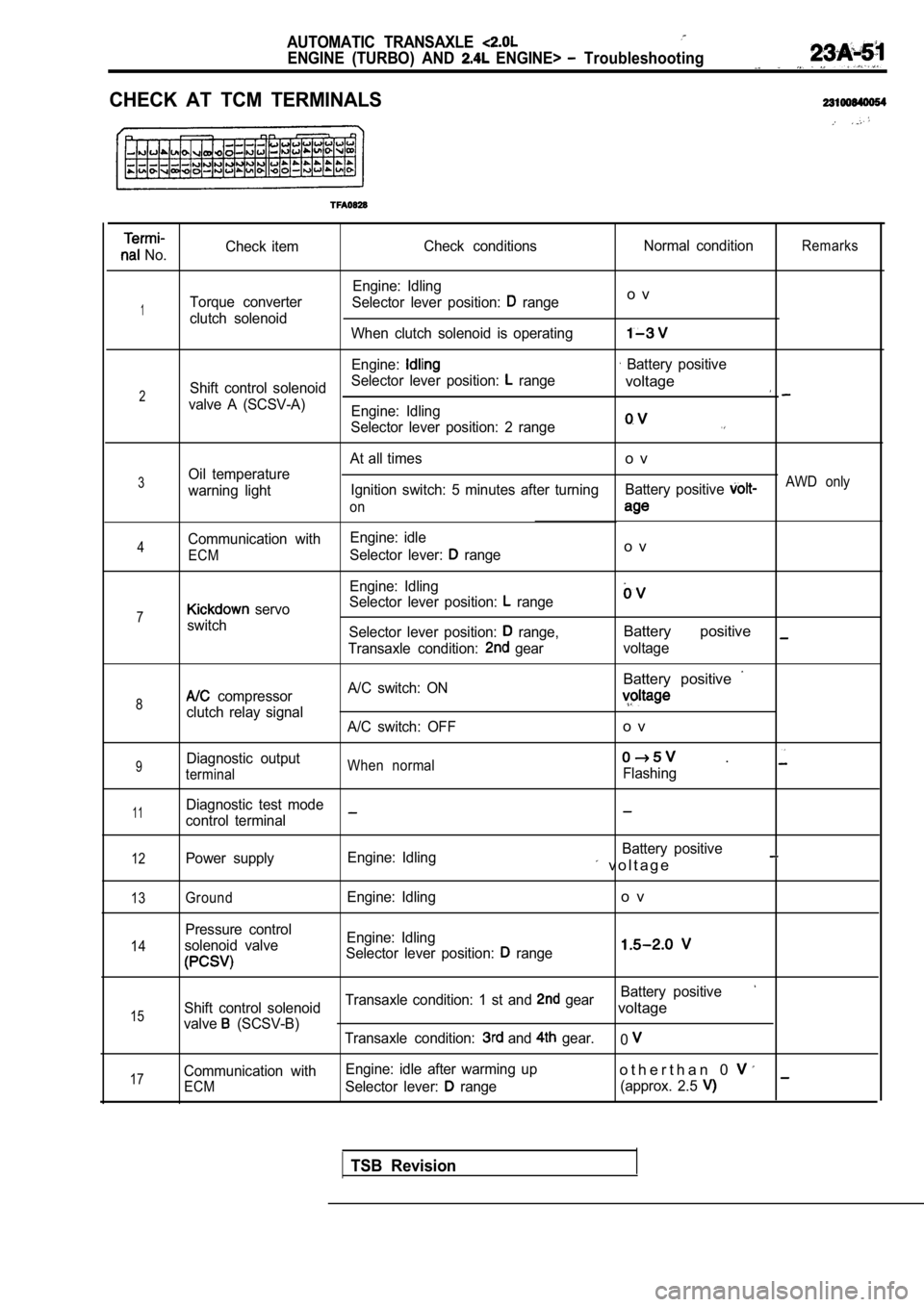
AUTOMATIC TRANSAXLE
ENGINE (TURBO) AND ENGINE> Troubleshooting
CHECK AT TCM TERMINALS
No.Check item
Check conditions Normal conditionRemarks
Engine: Idling
Torque converter Selector lever position:
rangeo v
1clutch solenoid
When clutch solenoid is operating
Engine: Battery positive
Shift control solenoid Selector lever position:
range
2voltage
valve A (SCSV-A)
Engine: Idling
Selector lever position: 2 range
At all timeso v
3Oil temperature
warning light Ignition switch: 5 minutes after turning
Battery positive AWD only
on
Communication with Engine: idle4Selector lever: rangeo vECM
Engine: Idling
Selector lever position:
range7 servo
switch Selector lever position:
range,Battery positive
Transaxle condition: gearvoltage
Battery positive
8 compressor A/C switch: ON
clutch relay signal
A/C switch: OFFo v
9Diagnostic outputWhen normal .
terminalFlashing
11Diagnostic test mode
control terminal
12Power supply Engine: Idling Battery positive v o l t a g e
13
14
15
17
GroundEngine: Idlingo v
Pressure control
solenoid valve Engine: Idling
Selector lever position:
range
Battery positive
Shift control solenoid Transaxle condition: 1 st and gearvoltage
valve (SCSV-B)
Transaxle condition: and gear.0
Communication with Engine: idle after warming upo t h e r t h a n 0
ECMSelector lever: range
(approx. 2.5
TSB Revision
Page 1060 of 2103
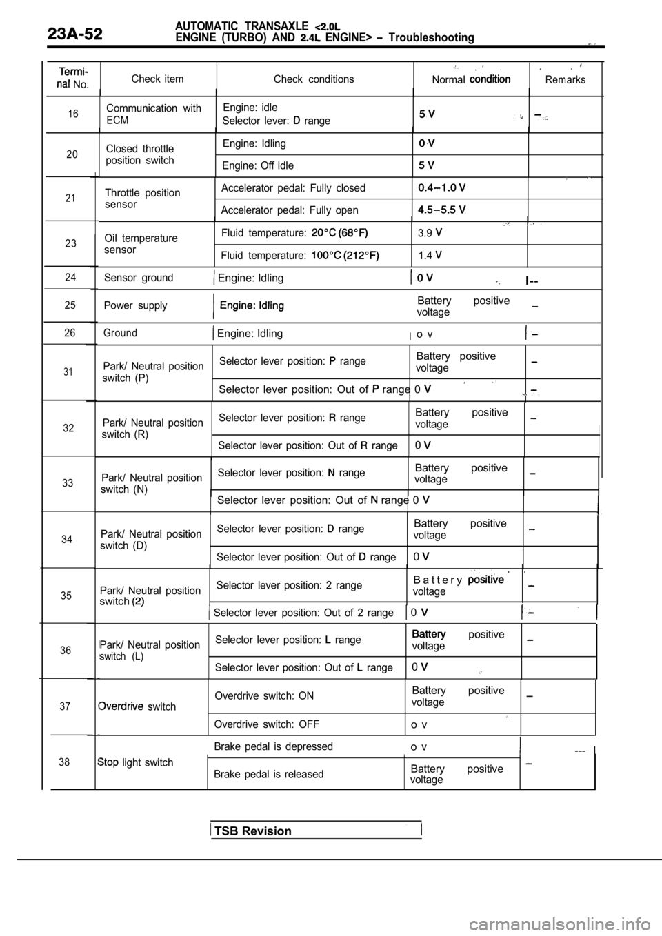
AUTOMATIC TRANSAXLE
ENGINE (TURBO) AND ENGINE> Troubleshooting
No.Check item
Check conditionsNormalRemarks
16Communication withEngine: idle
ECMSelector lever: range
20Closed throttle
position switch Engine: Idling
Engine: Off idle
21
23
24
25
26
31
32
33
34
35
36
37
38
Throttle position
sensor Accelerator pedal: Fully closed
Accelerator pedal: Fully open
Oil temperature
sensor Fluid temperature:
Fluid temperature:
3.9
1.4
Sensor ground Engine: IdlingI--
Power supplyBattery positive
voltage
Ground Engine: IdlingIo v
Park/ Neutral position
Selector lever position: rangeBattery positive
switch (P) voltage
Selector lever position: Out of range 0
Park/ Neutral position
Selector lever position: rangeBattery positive
switch (R) voltage
Selector lever position: Out of
range0
Park/ Neutral position Selector lever position: rangeBattery positive
switch (N) voltageSelector lever position: Out of range 0
Park/ Neutral position
Selector lever position: rangeBattery positive
switch (D) voltage
Selector lever position: Out of
range0
Park/ Neutral position Selector lever position: 2 rangeB a t t e r y
switchvoltage
Selector lever position: Out of 2 range 0
Park/ Neutral position
Selector lever position: range positive
switch (L)voltage
Selector lever position: Out of
range0
switch Overdrive switch: ON
Overdrive switch: OFF
Battery positive
voltage
o v
Brake pedal is depressedo v--- I
light switch Brake pedal is releasedBattery positive voltage
TSB Revision