MITSUBISHI SPYDER 1990 Service Repair Manual
Manufacturer: MITSUBISHI, Model Year: 1990, Model line: SPYDER, Model: MITSUBISHI SPYDER 1990Pages: 2103, PDF Size: 68.98 MB
Page 1771 of 2103
PARKING BRAKES, parking Brake Brake>
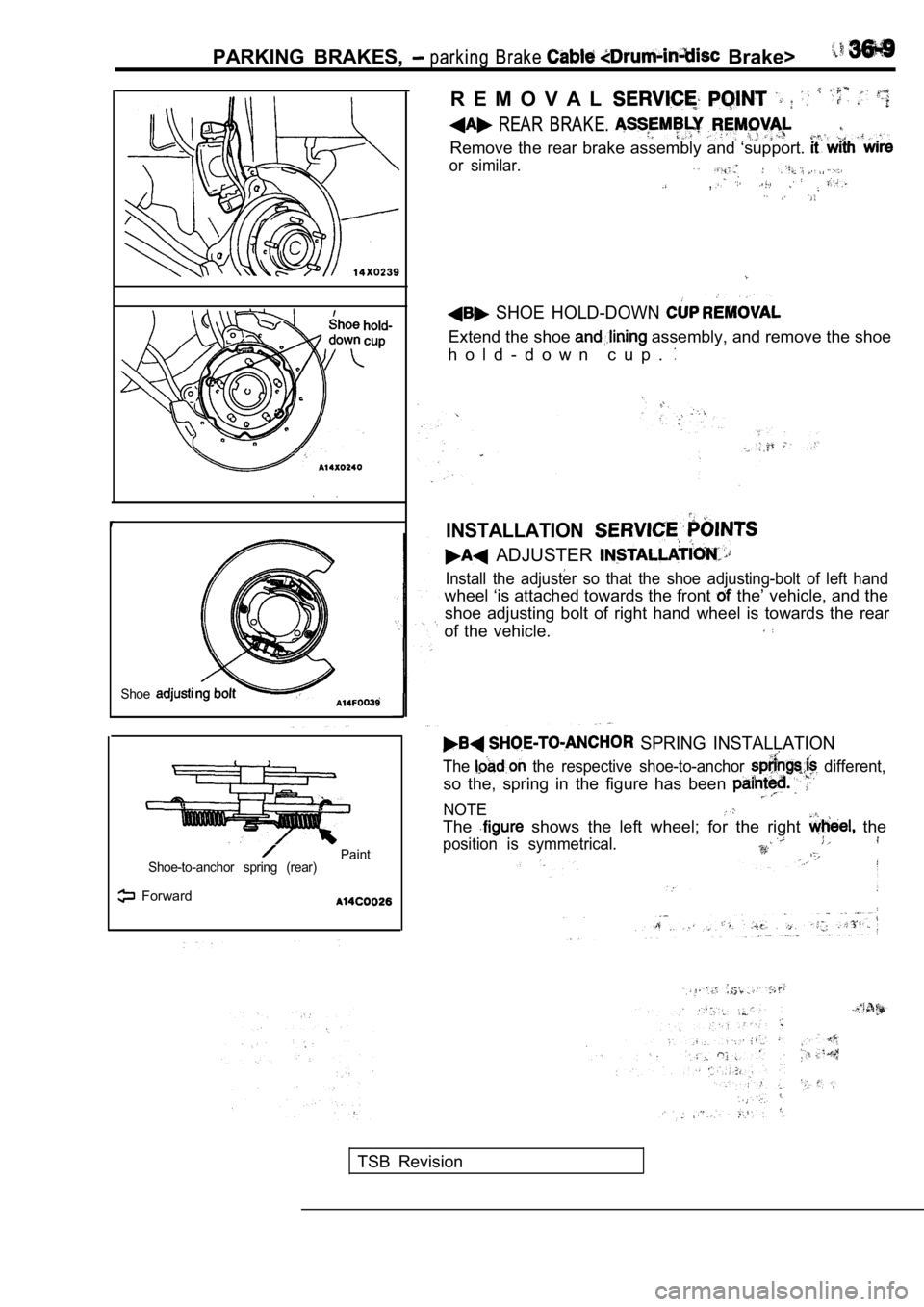
Shoe
Paint
Shoe-to-anchor spring (rear)
Forward
R E M O V A L
REAR BRAKE.
Remove the rear brake assembly and ‘support.
or similar.
,
SHOE HOLD-DOWN
Extend the shoe assembly, and remove the shoe
h o l d - d o w n c u p .
INSTALLATION
ADJUSTER
Install the adjuster so that the shoe adjusting-bol t of left hand
wheel ‘is attached towards the front the’ vehicle, and the
shoe adjusting bolt of right hand wheel is towards the rear
of the vehicle.
SPRING INSTALLATION
The the respective shoe-to-anchor different,
so the, spring in the figure has been
NOTE
The shows the left wheel; for the right the
position is symmetrical.
TSB Revision
Page 1772 of 2103
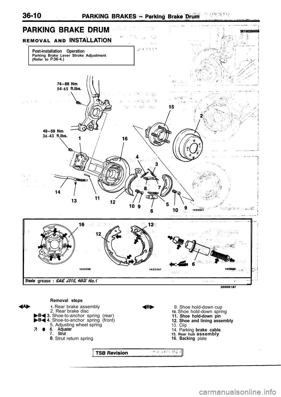
R E M O V A L A N D
Post-installation Operation ,
Parking Brake Lever Stroke Adjustment
(Refer to
54-65
36-43
grease .
Removal steps
1. Rear brake assembly2. Rear brake disc 9. Shoe hold-down cup
10. Shoe hold-down spring 3. Shoe-to-anchor spring (rear) 4. Shoe-to-anchor spring (front)11. Shoe hold-down pin
5. Adjusting wheel spring12. Shoe and lining assembly13.Clip
Page 1773 of 2103
PARKING BRAKES
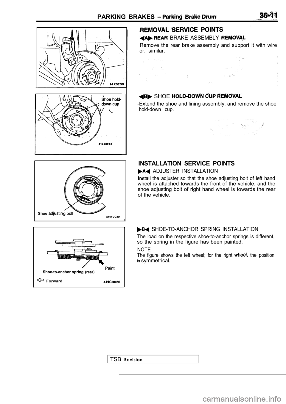
BRAKE ASSEMBLY
Remove the rear brake assembly and support it with wire
or. similar.
Shoe
Shoe-to-anchor spring(rear)
Forward
SHOE
-Extend the shoe and lining assembly, and remove th e shoe
hold-down cup.
INSTALLATION SERVICE POINTS
ADJUSTER INSTALLATION
the adjuster so that the shoe adjusting bolt of left hand
wheel is attached towards the front of the vehicle, and the
shoe adjusting bolt of right hand wheel is towards the rear
of the vehicle.
SHOE-TO-ANCHOR SPRING INSTALLATION
The load on the respective shoe-to-anchor springs i s different,
so the spring in the figure has been painted.
NOTE
The figure shows the left wheel; for the right
the position
is symmetrical.
TSB Revision
Page 1774 of 2103
PARKING BRAKES Parking Drum
INSPECTION
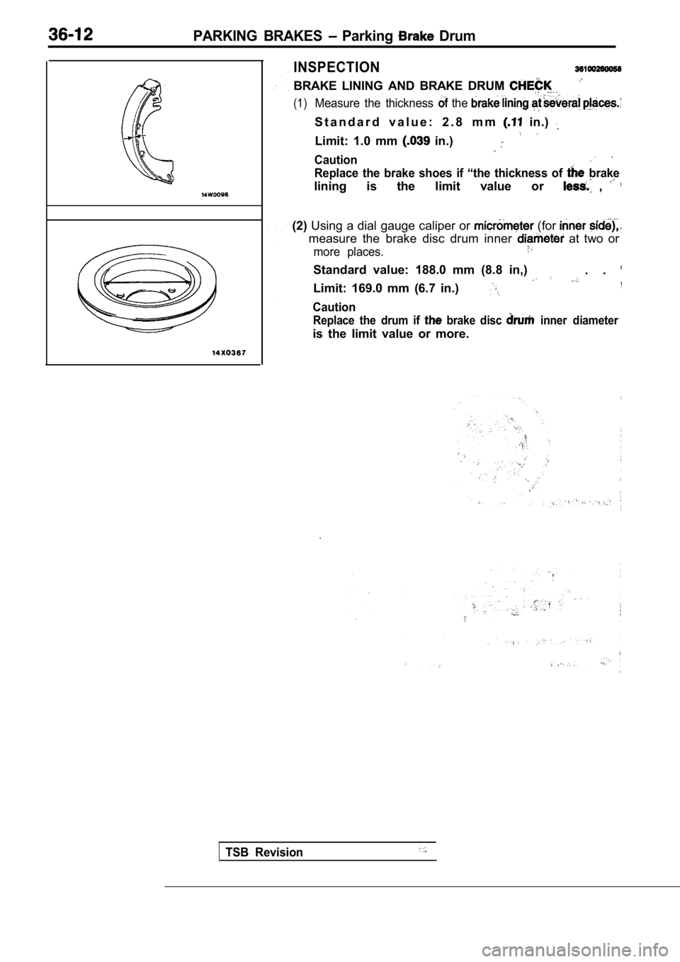
BRAKE LINING AND BRAKE DRUM
(1)Measure the thickness the
S t a n d a r d v a l u e : 2 . 8 m m in.)
Limit: 1.0 mm in.)
Caution
Replace the brake shoes if “the thickness of brake
lining is the limit value or ,
(2)Using a dial gauge caliper or (for
measure the brake disc drum inner at two or
more places.
Standard value: 188.0 mm (8.8 in,). .
Limit: 169.0 mm (6.7 in.)
Caution
Replace the drum if brake disc inner diameter
is the limit value or more.
TSB Revision
Page 1775 of 2103
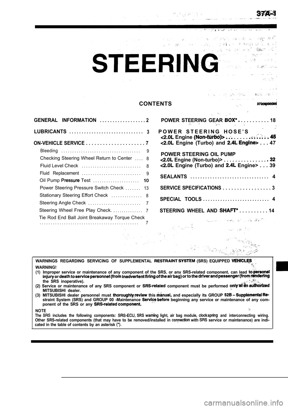
CONTENTS
GENERAL INFORMATION. . . . . . . . . . . . . . . . . . 2POWER STEERING GEAR . . . . . . . . . . 18
LUBRICANTS. . . . . . . . . . . . . . . . . . . . . . . . . . . . . .
3P O W E R S T E E R I N G H O S E ’ S
Engine . . . . .
ON-VEHICLE SERVICE . . . . . . . . . . . . . . . . . . . . . 7 Engine (Turbo) and . . . 47
Bleeding. . . . . . . . . . . . . . . . . . . . . . . . . . . . . . . . . . . .9
Checking Steering Wheel Return to Center
. . . .8
Fluid Level Check. . . . . . . . . . . . . . . . . . . . . . . . . . .8
Fluid Replacement. . . . . . . . . . . . . . . . . . . . . . . . . . .9
Oil Pump Test
. . . . . . . . . . . . . . . . . . . . .
Power Steering Pressure Switch Check
. . . . . . .13
Stationary Steering Effort Check. . . . . . . . . . . . . .8
Steering Angle Check. . . . . . . . . . . . . . . . . . . . . . . .7
Steering Wheel Free Play Check. . . . . . . . . . . . . . .7
Tie Rod End Ball Joint Breakaway Torque Check
. . . . . . . . . . . . . . . . . . . . . . . . . . . . . . . . . . . . . . . . . . . . .
7
POWER STEERING OIL PUMP
Engine (Non-turbo)> . . . . . . . . . . . . . . .
Engine (Turbo) and Engine> . . . 39
SEALANTS. . . . . . . . . . . . . . . . . . . . . . . . . . . . . . . .4
SERVICE SPECIFICATIONS . . . . . . . . . . . . . . . . . 3
SPECIAL TOOLS. . . . . . . . . . . . . . . . . . . . . . . . . . .4
STEERING WHEEL AND
. . . . . . . . . . 14
WARNINGS REGARDING SERVICING OF SUPPLEMENTAL (SRS) EQUIPPED
WARNING!(1)Improper service or maintenance of any component of the SRS, or any SRS-related component, can lead
the SRS inoperative).(2) Service or maintenance of any SRS component or component must be performed MITSUBISHI dealer.(3) MITSUBISHI dealer personnel must this and especially its GROUP straint System (SRS) and GROUP 00 -Maintenance beginning any service or maintenance of any com-
ponent of the SRS or any
NOTEThe includes the following components: SRS light, air bag module, and interconnecting wiring.Other SRS-related components (that may have to be r emoved/installed in with service or maintenance) are indi-
cated in the table of contents by an asterisk
Page 1776 of 2103
STEERING General Information
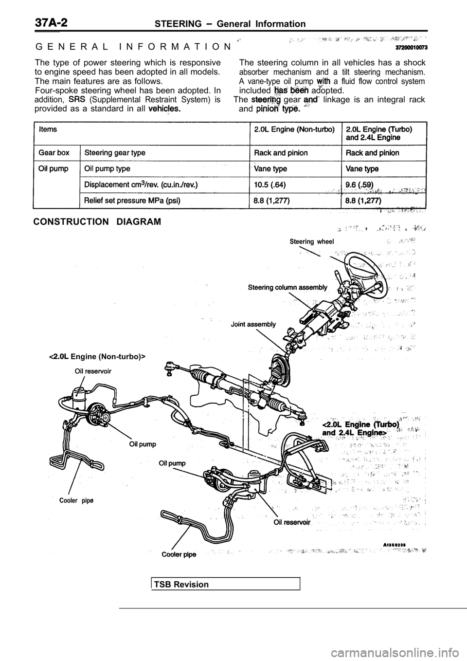
G E N E R A L I N F O R M A T I O N
The type of power steering which is responsive
to engine speed has been adopted in all models.
The main features are as follows. The steering column in all vehicles has a shock
absorber mechanism and a tilt steering mechanism.
Four-spoke steering wheel has been adopted. In
A vane-type oil pump a fluid flow control system
addition, (Supplemental Restraint System) is
included adopted.
provided as a standard in all
The gear linkage is an integral rack
and
CONSTRUCTION DIAGRAM,
Steering wheel
Cooler pipe
Engine (Non-turbo)>
TSB Revision
Page 1777 of 2103
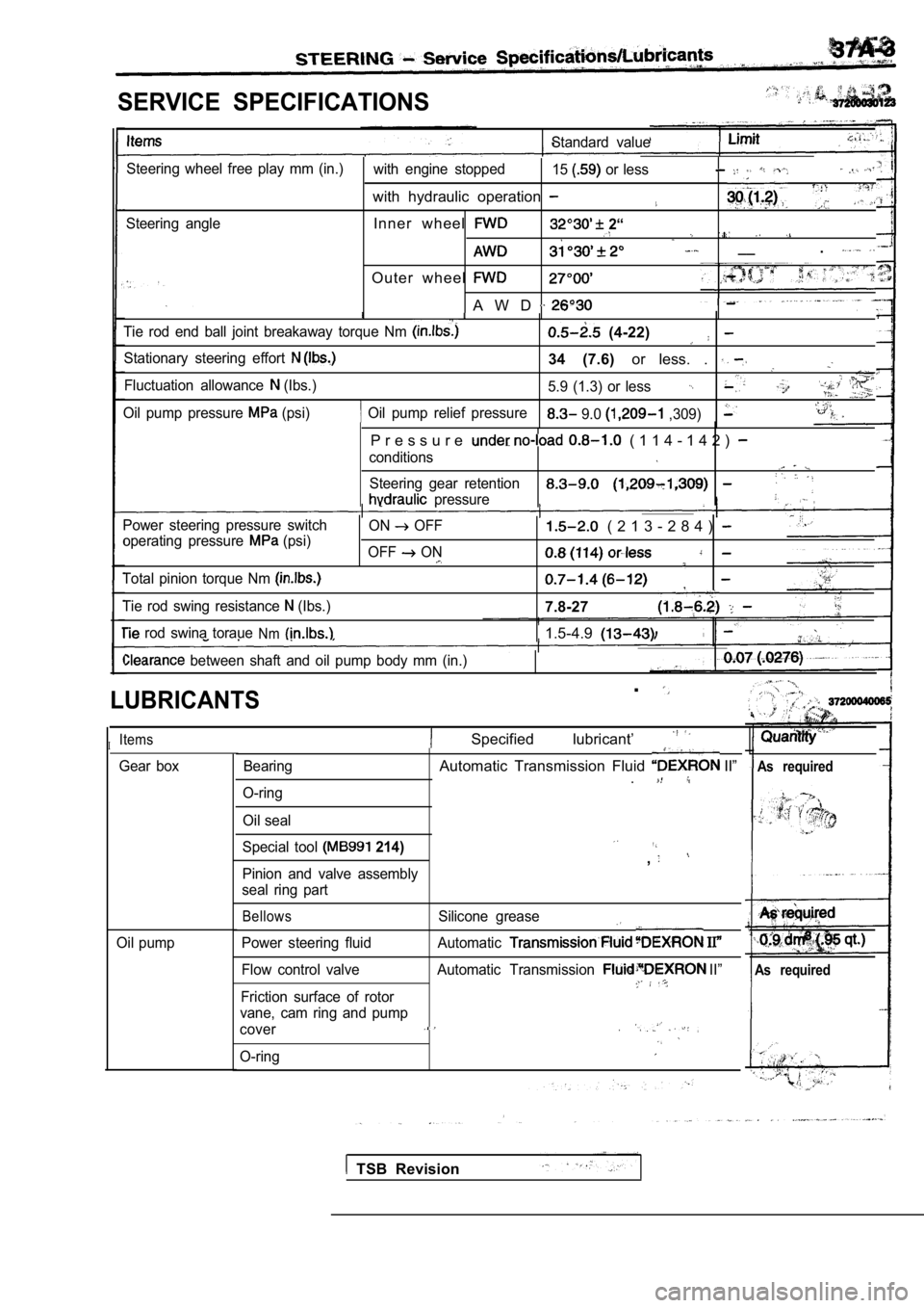
SERVICE SPECIFICATIONS
Standard value
Steering wheel free play mm (in.) with engine stopped15
or less,
with hydraulic operation
Steering angleInner wheel 2“
__
.
O u t e r w h e e l
A W D
Tie rod end ball joint breakaway torque Nm (4-22)
Stationary steering effort 34 (7.6) or less. .
Fluctuation allowance (Ibs.)
5.9 (1.3) or less
Oil pump relief pressureOil pump pressure (psi) 9.0 ,309)
P r e s s u r e ( 1 1 4 - 1 4 2 )
conditions
Steering gear retention
pressure
Power steering pressure switch
operating pressure
(psi)
Total pinion torque Nm
Tie rod swing resistance (Ibs.) ON
OFF
OFF
ON
( 2 1 3 - 2 8 4 )
7.8-27
rod swina toraueNm1.5-4.9
between shaft and oil pump body mm (in.)
LUBRICANTS
IItems
Bearing
O-ring
Oil seal
.
Specified lubricant’
Gear boxAutomatic Transmission Fluid II”
.As required
Oil pump Special tool
214)
Pinion and valve assembly
seal ring part
,
BellowsSilicone grease
Power steering fluid Automatic
Flow control valve Automatic Transmission II”
Friction surface of rotor
vane, cam ring and pump
cover.
O-ring
As required
TSB Revision
Page 1778 of 2103
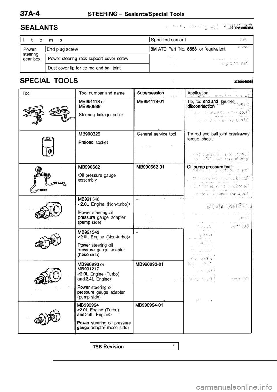
SEALANTS
Sealants/Special Tools
.
I t e m s Specified sealant
Power
steering
gear box End plug screw ATD Part ‘No. or ‘equivalent
Power steering rack support cover screw
Dust cover lip for tie rod end ball joint
SPECIAL TOOLS
Tool
0
Tool number and name
or
Steering linkage puller
socket
Oil pressure gauge
assembly
548
Engine (Non-turbo)>
Power steering oil
gauge adapter
side)
Engine (Non-turbo)>
steering oil
gauge adapter
side)
or
Engine (Turbo)
Engine>
steering oil
gauge adapter
pump side)
Engine (Turbo)
Engine>
steering oil pressure adapter (hose side)
Generalservice tool
TSBRevision,
Application
Tie, rod knuckle
Tie rod end ball joint breakaway
torque check
Page 1779 of 2103
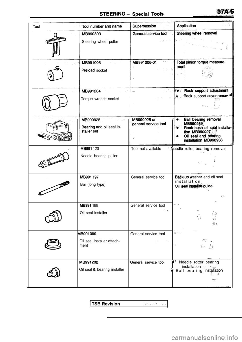
Special
Steering wheel puller
socket
Torque wrench socket
l support
120
Needle bearing puller
.
Tool not available roller bearing removal __
. .
197
Bar (long type) General service tool and oil seal
i n s t a l l a t i o n
Oil
199
Oil seal installerGeneral service tool
,
General service tool
Oil seal installer attach-
ment
General service tool Needle rotter bearing
Oil seal bearing installerinstallation -- B a l l b e a r i n g
TSB Revision
Page 1780 of 2103
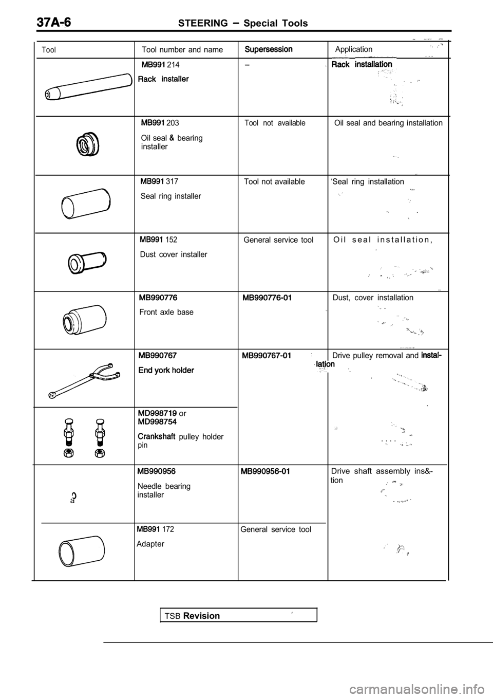
STEERING Special Tools
ToolTool number and name
214
203
Oil seal bearing
installer
Application
.
Tool not availableOil seal and bearing installation
317 Tool not available ‘Seal ring installation
Seal ring installer
.
152General service toolO i l s e a l i n s t a l l a t i o n ,
Dust cover installer
Dust, cover installation
Front axle base .. .
.
Drive pulley removal and
.
.
or
pulley holder. . . .pin
a
Needle bearing
installer
Drive shaft assembly ins&-
tion
.
172
Adapter General service tool
TSB
Revision