MITSUBISHI SPYDER 1990 Service Repair Manual
SPYDER 1990
MITSUBISHI
MITSUBISHI
https://www.carmanualsonline.info/img/19/57345/w960_57345-0.png
MITSUBISHI SPYDER 1990 Service Repair Manual
Trending: key battery, tires, coolant temperature, door lock, alarm, four wheel drive, stop start
Page 191 of 2103
ENGINECamshaft and Camshaft Seal
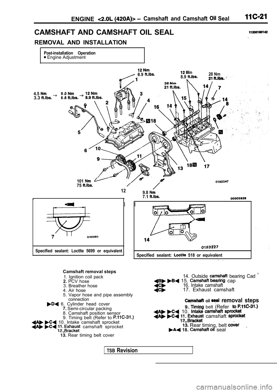
CAMSHAFT AND CAMSHAFT OIL SEAL
REMOVAL AND INSTALLATION
Post-installation Operation Engine Adjustment
4.53.3
8.9Mm8.928 Nm
10175
129.8
7
Specified sealant: Loctlte 5699 or equivalent
7.1
Specified sealant: 518 or equivalent
Camshaft removal steps1. Ignition coil pack
2. PCV hose
3. Breather hose
4. Air hose
5. Vapor hose and pipe assembly
connection
6. Cylinder head cover Semi-circular packing
8. Camshaft position sensor
9. Timing belt (Refer to
10. Intake camshaft sprocket camshaft sprocket
Rear timing belt cover
14. Outside bearing Cad 15. cap16. Intake camshaft17. Exhaust camshaft
oil removal steps
belt (Refer
10. camshaft
Rear timing, belt 18. seal
TSBRevision
Page 192 of 2103
ENGINECamshaft and
554
.
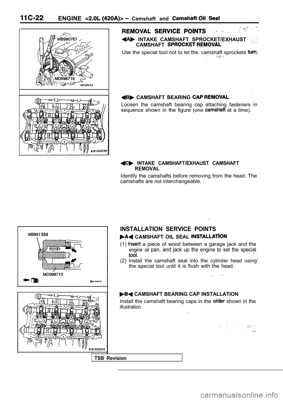
INTAKE CAMSHAFT SPROCKET/EXHAUST
CAMSHAFT
Use the special tool not to let the. camshaft sprockets
CAMSHAFT BEARING
Loosen the camshaft bearing cap attaching fasteners in
sequence shown in the figure (one
at a time).
INTAKE CAMSHAFT/EXHAUST CAMSHAFT REMOVAL
Identify the camshafts before removing from the hea d. The
camshafts are not interchangeable.
INSTALLATION SERVICE POINTS
CAMSHAFT OIL SEAL
(1) a piece of wood between a garage jack and the
engine oil pan, and jack up the engine to set the special .
(2) Install the camshaft seal into the cylinder hea d using’
the special tool until it is flush with the head.
CAMSHAFT BEARING CAP INSTALLATION
Install the camshaft bearing caps in the
shown in the
illustration.
TSB Revision
Page 193 of 2103
ENGINECamshaft and
67
a
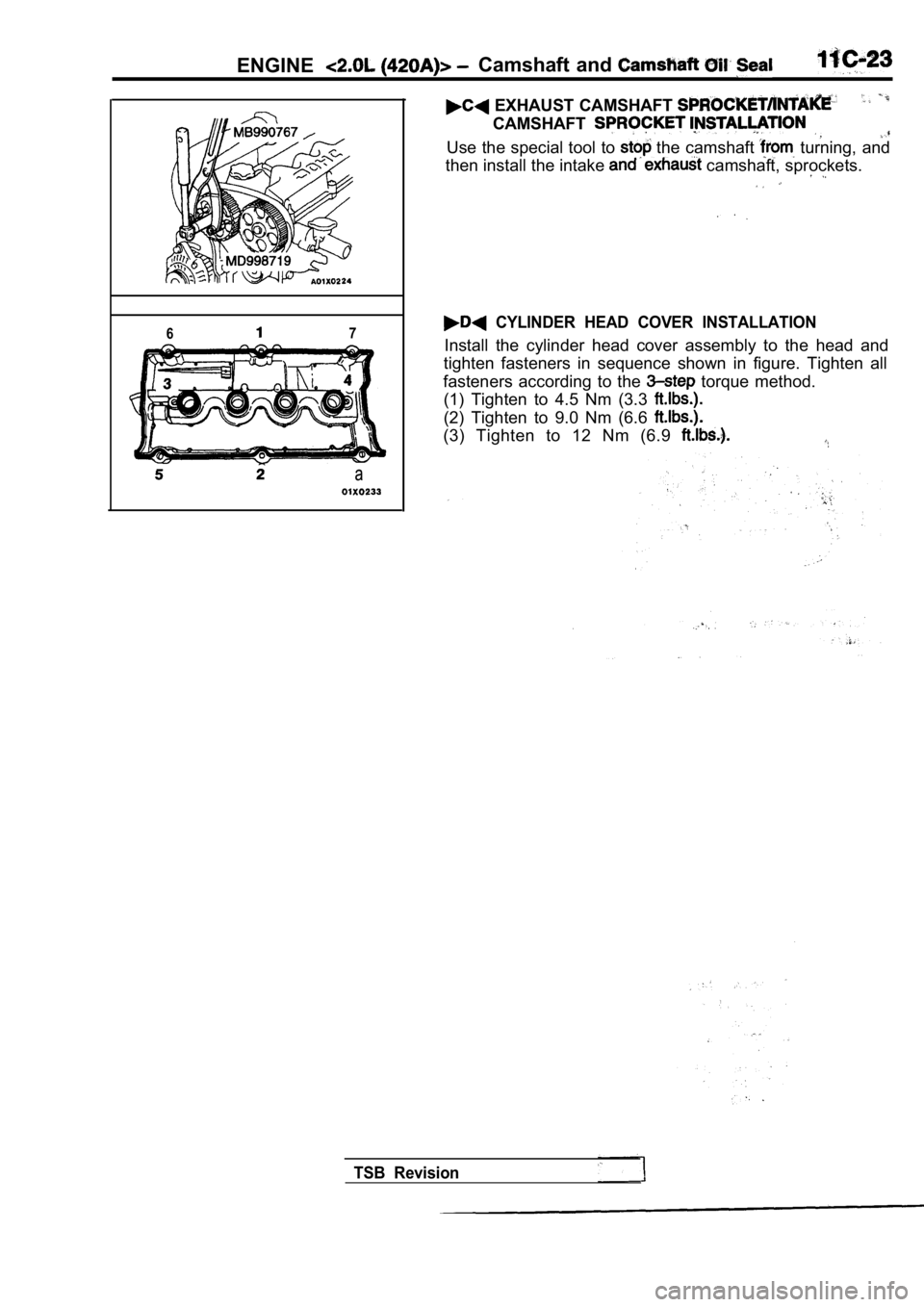
EXHAUST CAMSHAFT
CAMSHAFT
Use the special tool to the camshaft turning, and
then install the intake
camshaft, sprockets.
CYLINDER HEAD COVER INSTALLATION
Install the cylinder head cover assembly to the hea d and
tighten fasteners in sequence shown in figure. Tigh ten all
fasteners according to the
torque method.
(1) Tighten to 4.5 Nm (3.3
(2) Tighten to 9.0 Nm (6.6
(3) Tighten to 12 Nm (6.9
TSB Revision
Page 194 of 2103
ENGINE Oil Pan and Oil Screen
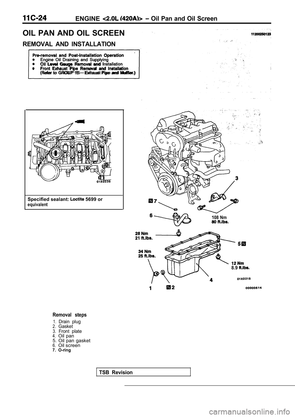
OIL PAN AND OIL SCREEN
REMOVAL AND INSTALLATION
and Post-installation OperationlEngine Oil Draining and SupplyingOil Level Gauge Removal and lFront Exhaust Pipe Removal and Installation
(Refer to GROUP 15 Exhaust Pipe and Muffler.)
Specified sealant: 5699 or
equivalent
TSB Revision
Removal steps
1.Drain plug2.Gasket3.Front plate4.Oil pan
5. Oil pan gasket
6.Oil screen7. O-ring
108 Nm
8.9
Page 195 of 2103
ENGINE Crankshaft Front
.
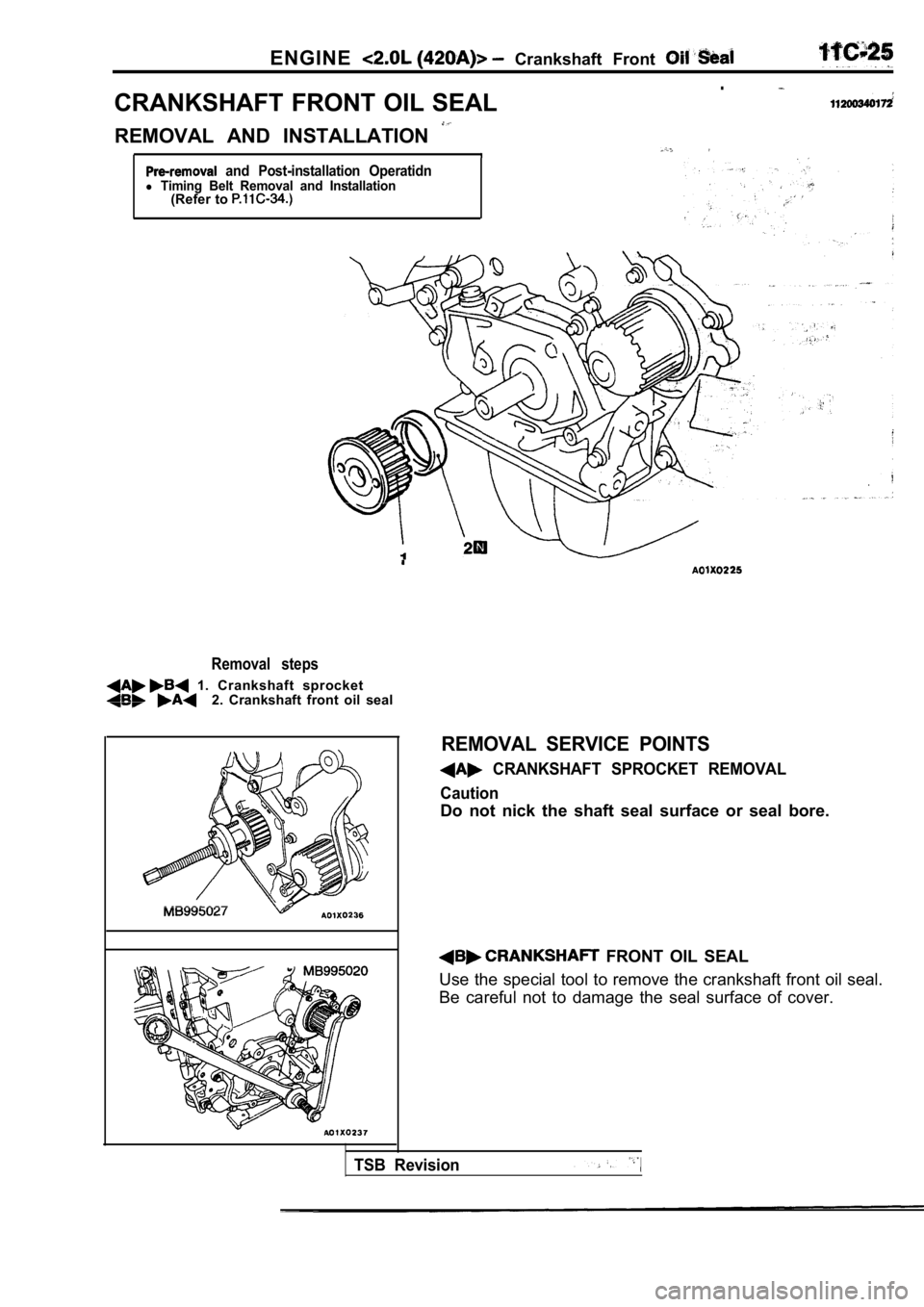
CRANKSHAFT FRONT OIL SEAL
REMOVAL AND INSTALLATION
and Post-installation Operatidnl Timing Belt Removal and Installation(Refer to
Removal steps
1. Crankshaft sprocket2. Crankshaft front oil seal
REMOVAL SERVICE POINTS
CRANKSHAFT SPROCKET REMOVAL
Caution
Do not nick the shaft seal surface or seal bore.
FRONT OIL SEAL
Use the special tool to remove the crankshaft front oil seal.
Be careful not to damage the seal surface of cover.
TSB Revision
Page 196 of 2103
ENGINE Crankshaft Front Oil Seal
I
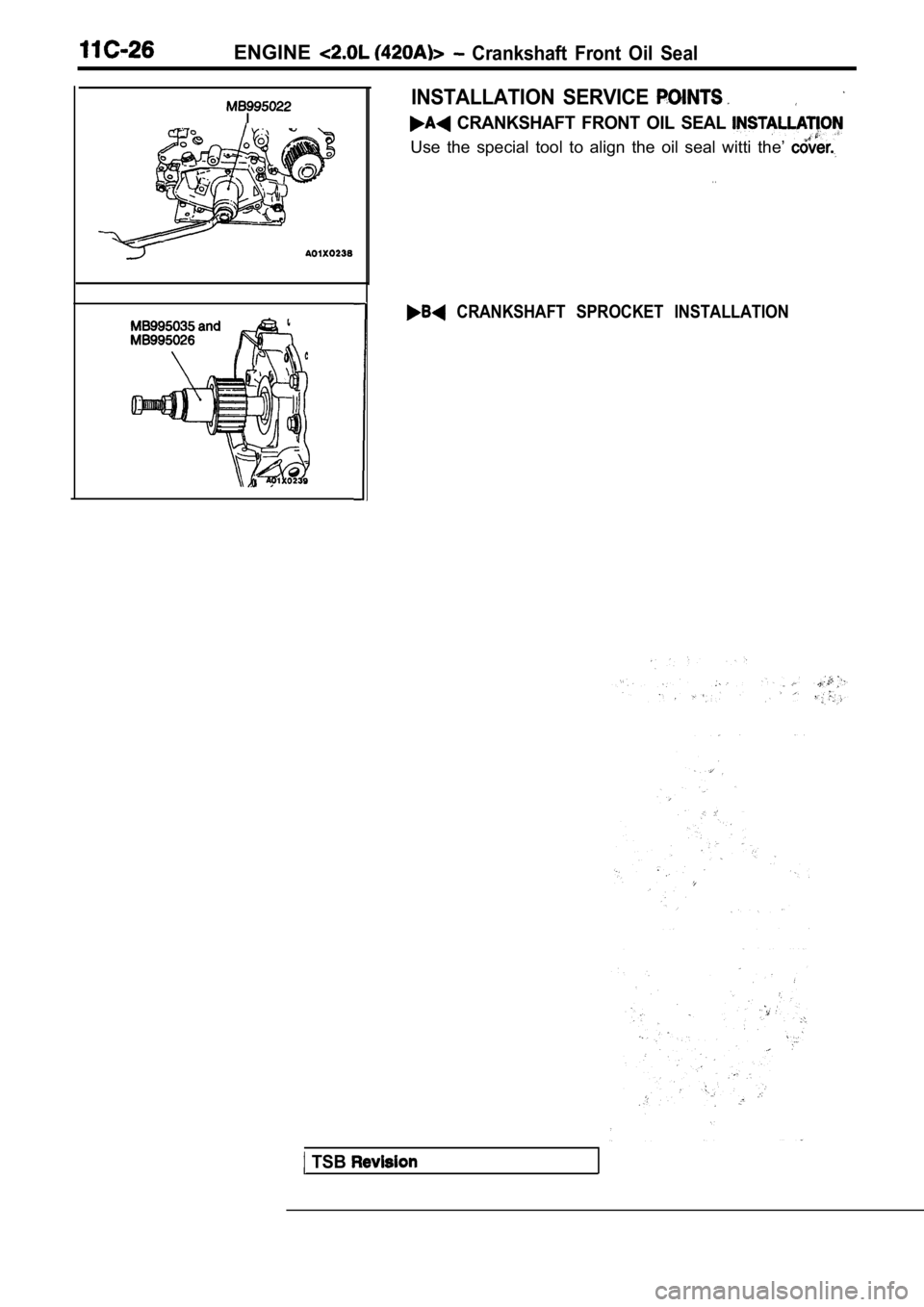
INSTALLATION SERVICE
CRANKSHAFT FRONT OIL SEAL
Use the special tool to align the oil seal witti the’
. .
CRANKSHAFT SPROCKET INSTALLATION
TSB
Page 197 of 2103
ENGINE Crankshaft Rear Oil Seal
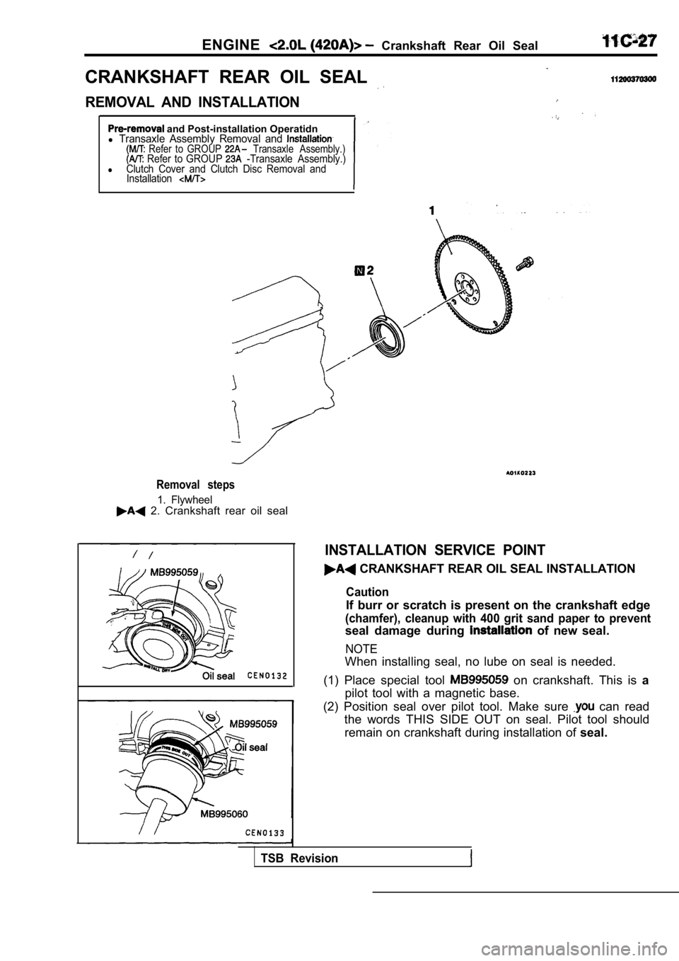
CRANKSHAFT REAR OIL SEAL
REMOVAL AND INSTALLATION
and Post-installation Operatidnl Transaxle Assembly Removal and Refer to GROUP Transaxle Assembly.) Refer to GROUP -Transaxle Assembly.)lClutch Cover and Clutch Disc Removal and Installation
Removal steps
1. Flywheel 2. Crankshaft rear oil seal
INSTALLATION SERVICE POINT
CRANKSHAFT REAR OIL SEAL INSTALLATION
Caution
If burr or scratch is present on the crankshaft edg e
(chamfer), cleanup with 400 grit sand paper to prev ent
seal damage during of new seal.
NOTE
When installing seal, no lube on seal is needed.
(1) Place special tool
on crankshaft. This is a
pilot tool with a magnetic base.
(2) Position seal over pilot tool. Make sure
can read
the words THIS SIDE OUT on seal. Pilot tool should
remain on crankshaft during installation of seal.
TSB Revision
Page 198 of 2103
ENGINE Crankshaft Rear Oil
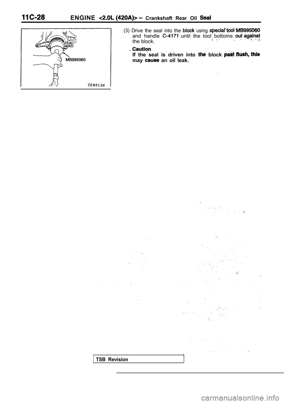
(3) Drive the seal into the using
and handle until the tool bottoms
the block.
.
If the seal is driven into block
may an oil leak.
TSB Revision
Page 199 of 2103
Cylinder Head
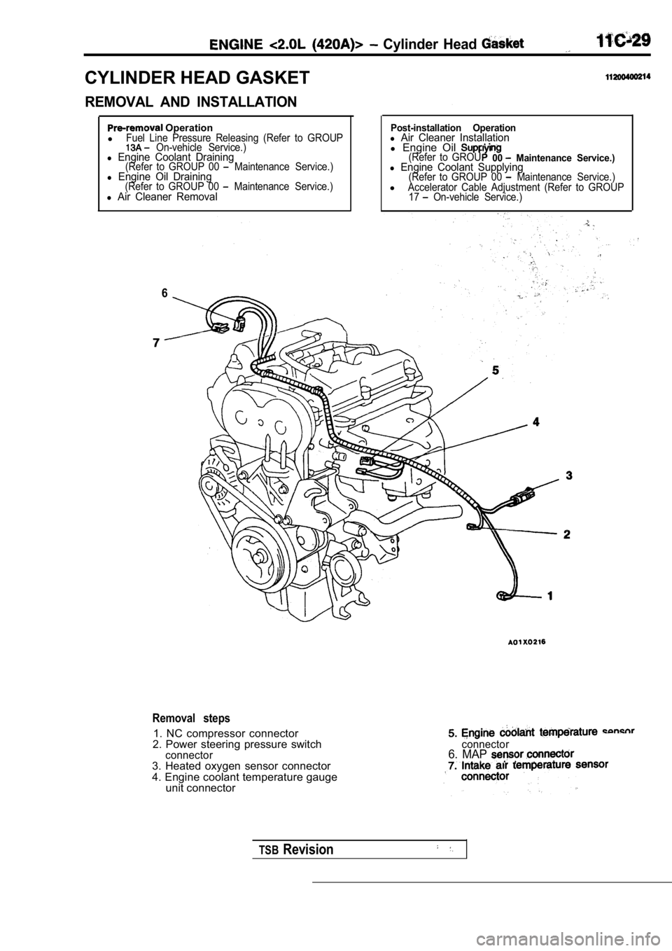
CYLINDER HEAD GASKET
REMOVAL AND INSTALLATION
Operation
lFuel Line Pressure Releasing (Refer to GROUP On-vehicle Service.)l Engine Coolant Draining(Refer to GROUP 00 Maintenance Service.)l Engine Oil Draining(Refer to GROUP 00 Maintenance Service.)l Air Cleaner Removal
6
Post-installation Operationl Air Cleaner Installationl Engine Oil (Refer to GROU00 Maintenance Service.)l Engine Coolant Supplying(Refer to GROUP 00 Maintenance Service.)lAccelerator Cable Adjustment (Refer to GROUP
17 On-vehicle Service.)
Removal steps
1. NC compressor connector
2. Power steering pressure switch
connector3. Heated oxygen sensor connector
4. Engine coolant temperature gauge unit connector
connector6. MAP
TSBRevision
Page 200 of 2103
ENGINE Cylinder Head
4.9 Nm
10
Engine oil
TSB Revision
2
15
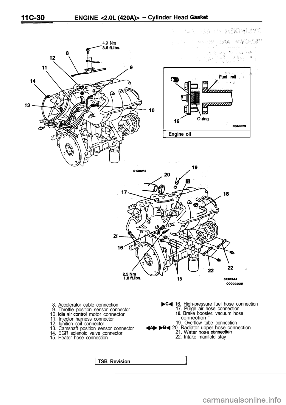
8. Accelerator cable connection
9. Throttle position sensor connector
10. air motor connector11. Injector harness connector
12. Ignition coil connector
13. Camshaft position sensor connector
14. EGR solenoid valve connector
15. Heater hose connection
16. High-pressure fuel hose connection 17. Purge air hose connection
Brake booster. vacuum hoseconnection
19. Overflow tube connection
20. Radiator upper hose connection 21. Water hose
22. Intake manifold stay
Trending: door lock, water pump, mileage, tires, oil viscosity, towing, coolant temperature
