NISSAN LATIO 2009 Service Repair Manual
Manufacturer: NISSAN, Model Year: 2009, Model line: LATIO, Model: NISSAN LATIO 2009Pages: 4331, PDF Size: 58.04 MB
Page 3341 of 4331
GW-38< SERVICE INFORMATION >
POWER WINDOW SYSTEM
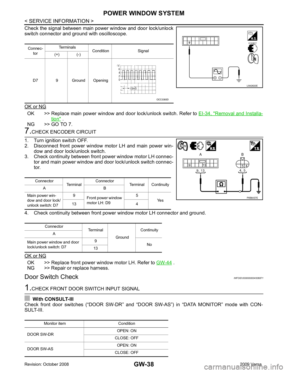
Check the signal between main power window and door lock/unlock
switch connector and ground with oscilloscope.
OK or NG OK >> Replace main power window and door lock/unlock switch. Refer to
EI-34, " Removal and Installa-
tion " .
NG >> GO TO 7. 7.
CHECK ENCODER CIRCUIT
1. Turn ignition switch OFF.
2. Disconnect front power window motor LH and main power win-
dow and door lock/unlock switch.
3. Check continuity between front power window motor LH connec-
tor and main power window and door lock/unlock switch connec-
tor.
4. Check continuity between front power window motor LH connector and ground.
OK or NG OK >> Replace front power window motor LH. Refer to
GW-44 .
NG >> Repair or replace harness.
Door Switch Check INFOID:00000000043068711.
CHECK FRONT DOOR SWITCH INPUT SIGNAL
With CONSULT-III
Check front door switches (“DOOR SW-DR” and “D OOR SW-AS”) in “DATA MONITOR” mode with CON-
SULT-III. Connec-
tor Terminals
Condition Signal
(+) (-)
D7 9 Ground Opening LIIA2633E
OCC3383D
Connector TerminalConnector
Terminal Continuity
A B
Main power win-
dow and door lock/
unlock switch: D7 9
Front power window
motor LH: D9 5
Yes
13 4
Connector Terminal
GroundContinuity
A
Main power window and door
lock/unlock switch: D7 9
No
13 PIIB6437E
Monitor item Condition
DOOR SW-DR OPEN: ON
CLOSE: OFF
DOOR SW-AS OPEN: ON
CLOSE: OFF
Page 3342 of 4331
GW
N
O P
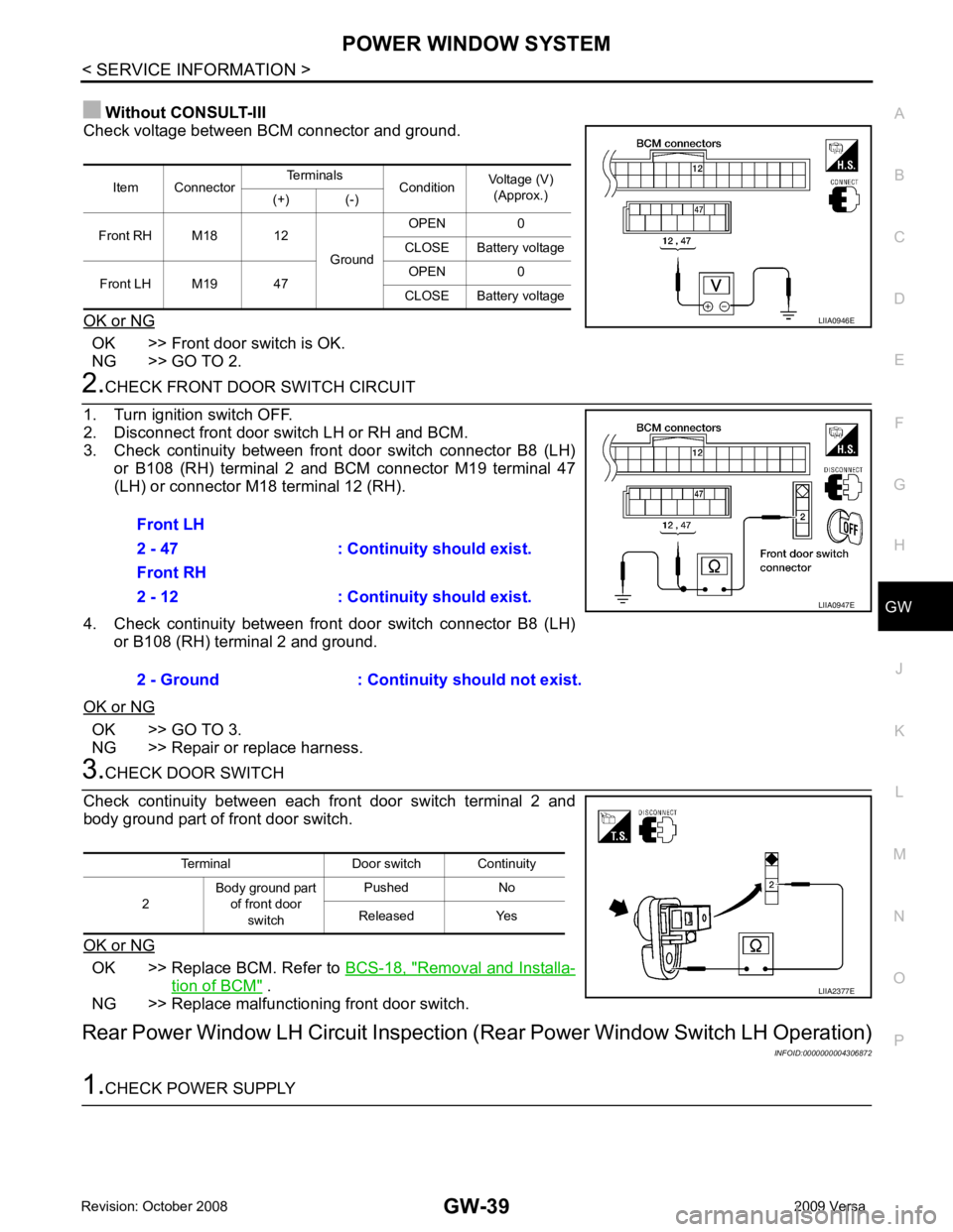
Without CONSULT-III
Check voltage between BCM connector and ground.
OK or NG OK >> Front door switch is OK.
NG >> GO TO 2. OK >> GO TO 3.
NG >> Repair or replace harness. OK >> Replace BCM. Refer to
BCS-18, " Removal and Installa-
tion of BCM " .
NG >> Replace malfunctioning front door switch.
Rear Power Window LH Circuit Inspection (Rear Power Window Switch LH Operation)
INFOID:0000000004306872
Page 3343 of 4331
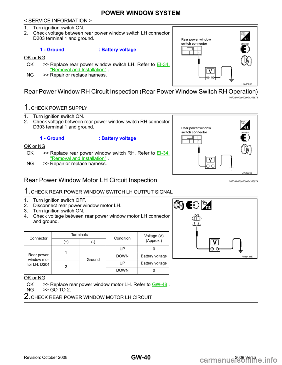
OK >> Replace rear power window switch LH. Refer to
EI-34," Removal and Installation " .
NG >> Repair or replace harness.
Rear Power Window RH Circuit Inspection (R ear Power Window Switch RH Operation)
INFOID:0000000004306873OK >> Replace rear power window switch RH. Refer to
EI-34," Removal and Installation " .
NG >> Repair or replace harness.
Rear Power Window Motor LH Circuit Inspection INFOID:0000000004306874OK >> Replace rear power window motor LH. Refer to
GW-48 .
NG >> GO TO 2.
Page 3344 of 4331
GW
N
O P
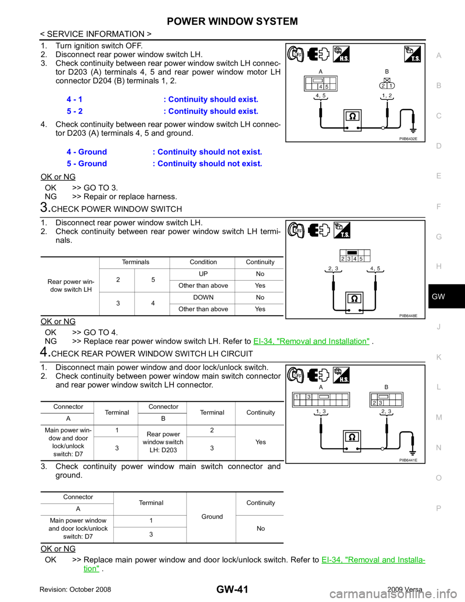
1. Turn ignition switch OFF.
2. Disconnect rear power window switch LH.
3. Check continuity between rear power window switch LH connec-
tor D203 (A) terminals 4, 5 and rear power window motor LH
connector D204 (B) terminals 1, 2.
4. Check continuity between rear power window switch LH connec- tor D203 (A) terminals 4, 5 and ground.
OK or NG OK >> GO TO 3.
NG >> Repair or replace harness. OK >> GO TO 4.
NG >> Replace rear power window switch LH. Refer to EI-34, " Removal and Installation " .
OK >> Replace main power window and door lock/unlock switch. Refer to
EI-34, " Removal and Installa-
tion " .
4 - 1 : Continuity should exist.
5 - 2 : Continuity should exist.
4 - Ground : Continuity should not exist.
5 - Ground : Continuity should not exist.
Page 3345 of 4331
GW-42< SERVICE INFORMATION >
POWER WINDOW SYSTEM
NG >> Repair or replace harness.
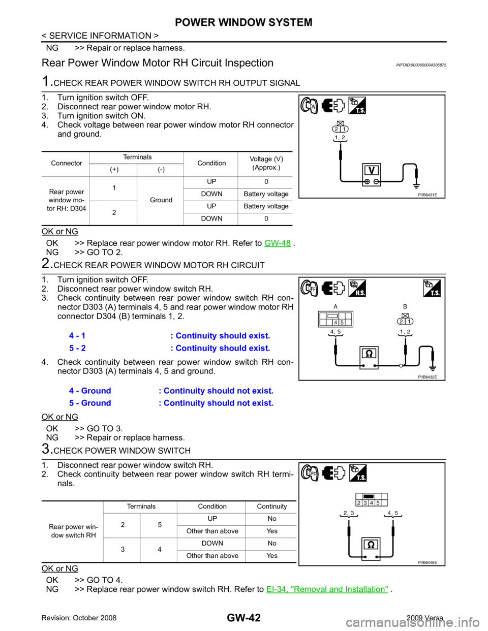
Rear Power Window Moto r RH Circuit Inspection INFOID:00000000043068751.
CHECK REAR POWER WINDOW SWITCH RH OUTPUT SIGNAL
1. Turn ignition switch OFF.
2. Disconnect rear power window motor RH.
3. Turn ignition switch ON.
4. Check voltage between rear power window motor RH connector
and ground.
OK or NG OK >> Replace rear power window motor RH. Refer to
GW-48 .
NG >> GO TO 2. 2.
CHECK REAR POWER WINDOW MOTOR RH CIRCUIT
1. Turn ignition switch OFF.
2. Disconnect rear power window switch RH.
3. Check continuity between rear power window switch RH con- nector D303 (A) terminals 4, 5 and rear power window motor RH
connector D304 (B) terminals 1, 2.
4. Check continuity between rear power window switch RH con- nector D303 (A) terminals 4, 5 and ground.
OK or NG OK >> GO TO 3.
NG >> Repair or replace harness. 3.
CHECK POWER WINDOW SWITCH
1. Disconnect rear power window switch RH.
2. Check continuity between rear power window switch RH termi-
nals.
OK or NG OK >> GO TO 4.
NG >> Replace rear power window switch RH. Refer to EI-34, " Removal and Installation " .
Connector
Terminals
ConditionVoltage (V)
(Approx.)
(+) (-)
Rear power
window mo-
tor RH: D304 1
Ground UP 0
DOWN Battery voltage
2 UP Battery voltage
DOWN 0 PIIB6431E
4 - 1 : Continuity should exist.
5 - 2 : Continuity should exist.
4 - Ground : Continuity should not exist.
5 - Ground : Continuity should not exist. PIIB6432E
Rear power win-
dow switch RH Terminals Condition Continuity
2 5 UP No
Other than above Yes
3 4 DOWN No
Other than above Yes PIIB6448E
Page 3346 of 4331
GW
N
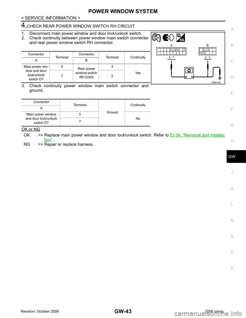
O P OK >> Replace main power window and door lock/unlock switch. Refer to
EI-34, " Removal and Installa-
tion " .
NG >> Repair or replace harness. Connector
TerminalConnector
Terminal Continuity
A B
Main power win- dow and door
lock/unlock switch D7 5
Rear power
window switch RH D303 3
Yes
7 2
Connector Terminal
GroundContinuity
A
Main power window
and door lock/unlock switch D7 5
No
7
Page 3347 of 4331
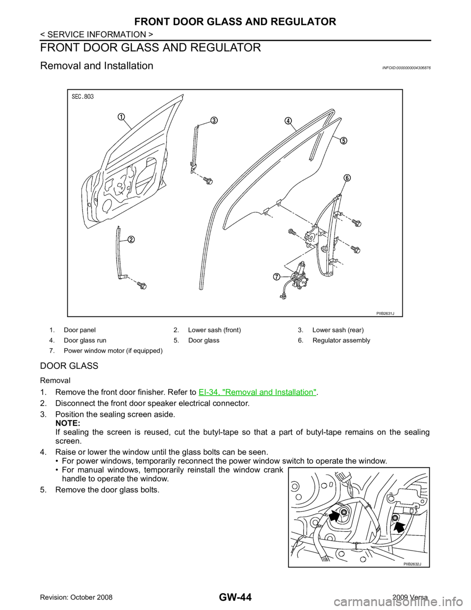
Removal and Installation " .
2. Disconnect the front door speaker electrical connector.
3. Position the sealing screen aside. NOTE:
If sealing the screen is reused, cut the butyl-tape so that a part of butyl-tape remains on the sealing
screen.
4. Raise or lower the window until the glass bolts can be seen. • For power windows, temporarily reconnect the power window switch to operate the window.
• For manual windows, temporarily reinstall the window crank handle to operate the window.
5. Remove the door glass bolts. 1. Door panel 2. Lower sash (front) 3. Lower sash (rear)
4. Door glass run 5. Door glass 6. Regulator assembly
7. Power window motor (if equipped) PIIB2632J
Page 3348 of 4331
GW
N
O P
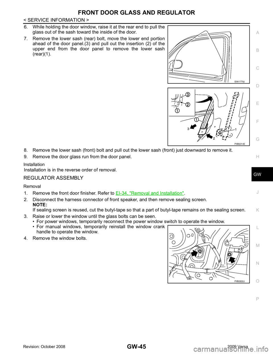
6. While holding the door window, raise it at the rear end to pull the
glass out of the sash toward the inside of the door.
7. Remove the lower sash (rear) bolt, move the lower end portion ahead of the door panel.(3) and pull out the insertion (2) of the
upper end from the door panel to remove the lower sash
(rear)(1).
8. Remove the lower sash (front) bolt and pull out the lower sash (front) just downward to remove it.
9. Remove the door glass run from the door panel.
Installation Installation is in the reverse order of removal.
REGULATOR ASSEMBLY
Removal 1. Remove the front door finisher. Refer to EI-34, " Removal and Installation " .
2. Disconnect the harness connector of front speaker, and then remove sealing screen. NOTE:
If sealing screen is reused, cut the butyl-tape so that a part of butyl-tape remains on the sealing screen.
3. Raise or lower the window until the glass bolts can be seen. • For power windows, temporarily reconnect t he power window switch to operate the window.
• For manual windows, temporarily reinstall the window crank handle to operate the window.
4. Remove the window bolts. PIIB6314E
PIIB2632J
Page 3349 of 4331
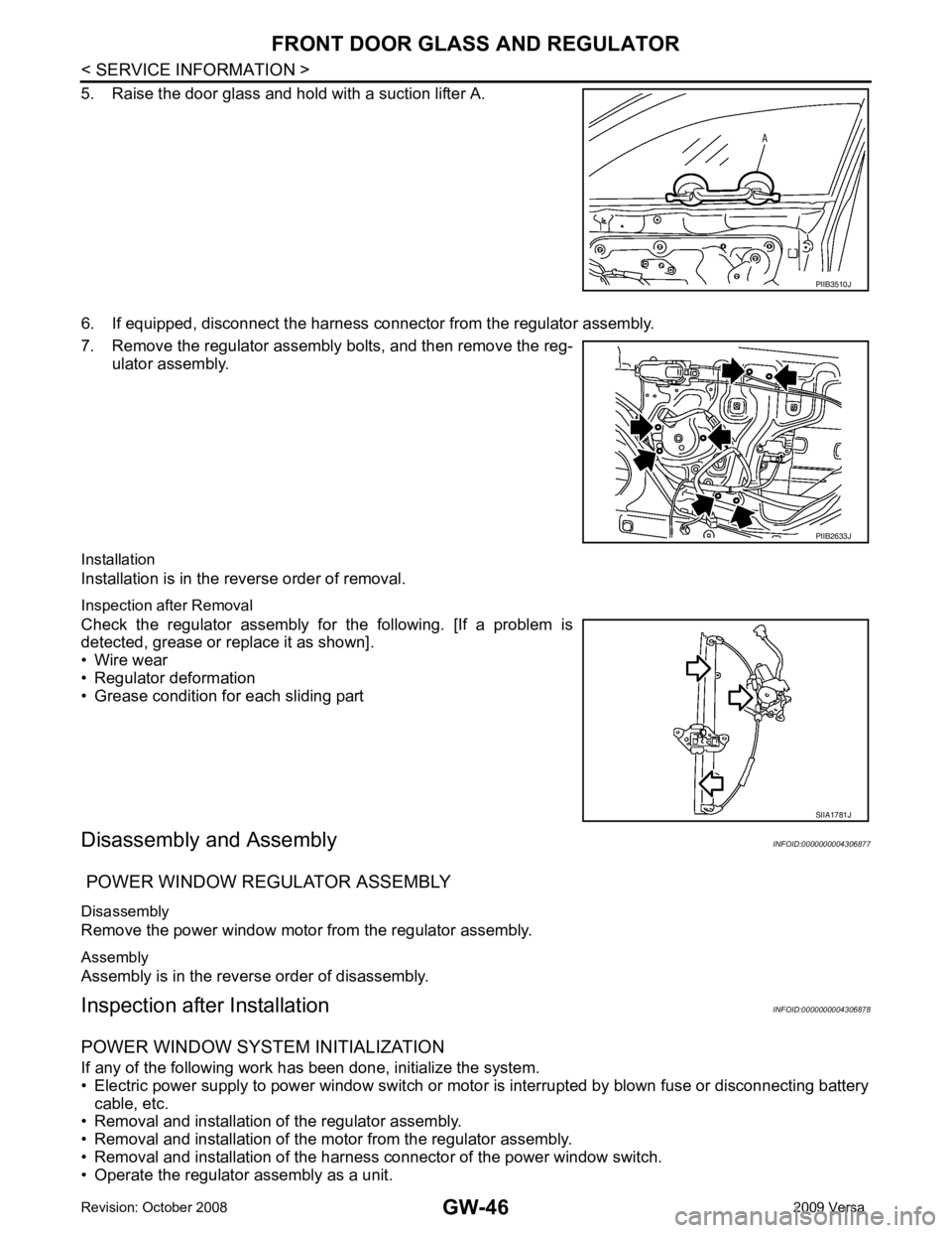
PIIB2633J
Page 3350 of 4331
GW
N
O P
• Removal and installation of the door glass.
• Removal and installation of the door glass run.
Initialization After installing each component to the vehicle, follow the steps below.
1. Disconnect the battery negative c able or disconnect power window switch's harness connector tempo-
rarily, then reconnect after at least 1 minute.
2. Turn ignition switch ON.
3. Open the window to its full width by operating the power window switch. (Exclude this procedure if the
window is already fully opened).
4. Move the power window switch in the up direction (auto close position) and hold. Keep holding the switch
even when window is completely closed, and then release after 4 seconds have passed.
5. Inspection of the ant i-pinch system function.
NOTE:
Initialization may be cancelled with continuous opening and closing operation. In this case, initialize the
system.
INSPECT THE FUNCTION OF THE ANTI-PINCH SYSTEM 1. Fully open the door glass.
2. Place a wooden piece (wooden hammer handle, etc.) near the fully closed position.
3. Carry out fully closing operation with auto up switch.
• Check that the glass reverses without pinching the w ooden piece, is lowered approx.150 mm (5.91 in) or for
2 seconds and then stops.
• The glass should not be raised with power window main switch while it is reversing or lowering.
CAUTION:
• Use care to avoid being pinched du ring the inspection. Do not use a hand, etc. in place of the
wooden piece durin g the inspection.
• Check that auto up function is normal before inspection, following the system initialization.
FITTING INSPECTION • Make sure the glass is securely fit into the glass run groove.
• Lower the glass slightly [approx. 10 to 20 mm (0.39 to 0.79 in)] and make sure the clearance to the sash is parallel. If the clearance between the glass and sash is not parallel, loosen the regulator bolts, guide rail
bolts, and the glass and guide rail bolts to correct the glass position.
• Make sure the system is normal with raising and lowering the glass.