NISSAN LATIO 2010 Service Repair Manual
LATIO 2010
NISSAN
NISSAN
https://www.carmanualsonline.info/img/5/57358/w960_57358-0.png
NISSAN LATIO 2010 Service Repair Manual
Trending: fold seats, Acs, brake sensor, Electrical, fuse diagram, maintenance schedule, towing
Page 281 of 3745
AT-264
< SERVICE INFORMATION >
DISASSEMBLY
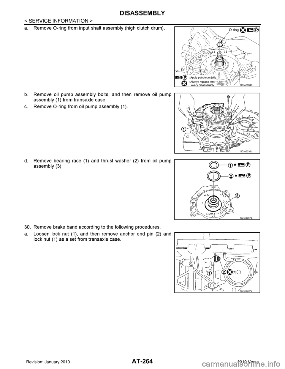
a. Remove O-ring from input shaft assembly (high clutch drum).
b. Remove oil pump assembly bolts, and then remove oil pumpassembly (1) from transaxle case.
c. Remove O-ring from oil pump assembly (1).
d. Remove bearing race (1) and thrust washer (2) from oil pump assembly (3).
30. Remove brake band according to the following procedures.
a. Loosen lock nut (1), and then remove anchor end pin (2) and lock nut (1) as a set from transaxle case.
SCIA5634E
SCIA6036J
SCIA6957E
SCIA6037J
Revision: January 20102010 Versa
Page 282 of 3745
DISASSEMBLYAT-265
< SERVICE INFORMATION >
DE
F
G H
I
J
K L
M A
B
AT
N
O P
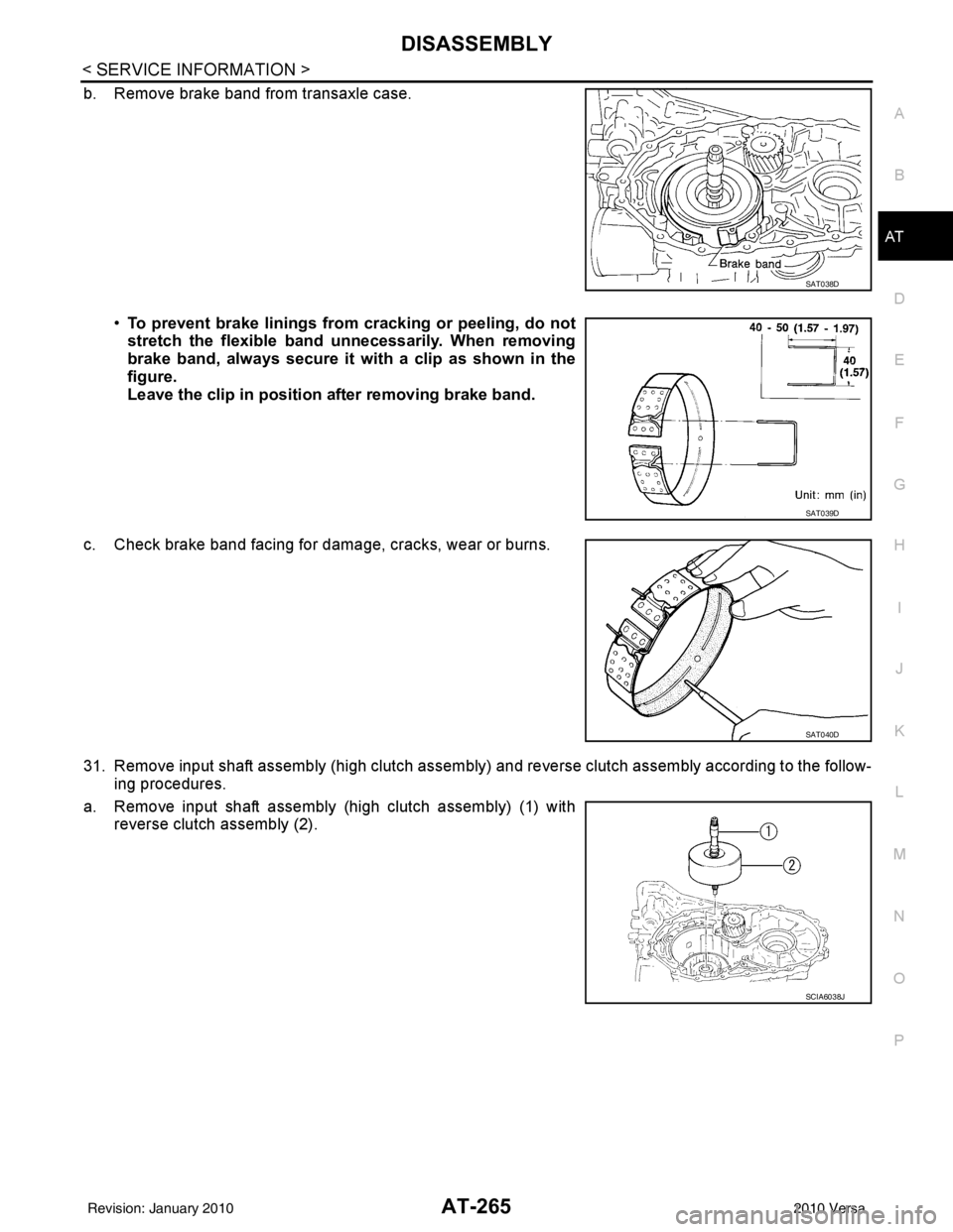
b. Remove brake band from transaxle case.
•To prevent brake linings from cracking or peeling, do not
stretch the flexible band unnecessarily. When removing
brake band, always secure it wi th a clip as shown in the
figure.
Leave the clip in position after removing brake band.
c. Check brake band facing for damage, cracks, wear or burns.
31. Remove input shaft assembly (high clutch assembly ) and reverse clutch assembly according to the follow-
ing procedures.
a. Remove input shaft assembly (high clutch assembly) (1) with reverse clutch assembly (2).
SAT038D
SAT039D
SAT040D
SCIA6038J
Revision: January 20102010 Versa
Page 283 of 3745
AT-266
< SERVICE INFORMATION >
DISASSEMBLY
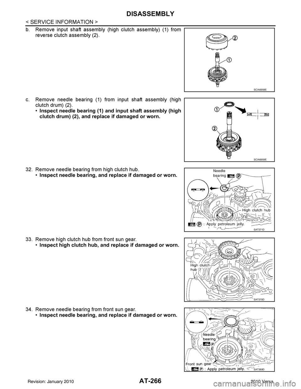
b. Remove input shaft assembly (high clutch assembly) (1) fromreverse clutch assembly (2).
c. Remove needle bearing (1) from input shaft assembly (high clutch drum) (2).
•Inspect needle bearing (1) and input shaft assembly (high
clutch drum) (2), and re place if damaged or worn.
32. Remove needle bearing from high clutch hub. •Inspect needle bearing, and replace if damaged or worn.
33. Remove high clutch hub from front sun gear. •Inspect high clutch hub, and replace if damaged or worn.
34. Remove needle bearing from front sun gear. •Inspect needle bearing, and replace if damaged or worn.
SCIA6958E
SCIA6959E
SAT371D
SAT370D
SAT369D
Revision: January 20102010 Versa
Page 284 of 3745
DISASSEMBLYAT-267
< SERVICE INFORMATION >
DE
F
G H
I
J
K L
M A
B
AT
N
O P
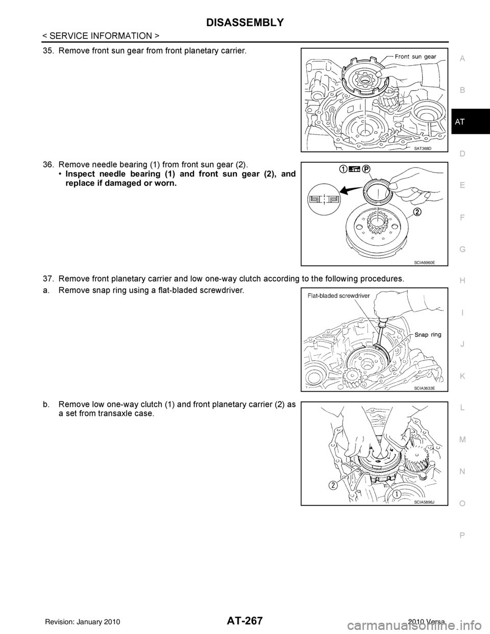
35. Remove front sun gear from front planetary carrier.
36. Remove needle bearing (1) from front sun gear (2). •Inspect needle bearing (1) an d front sun gear (2), and
replace if damaged or worn.
37. Remove front planetary carrier and low one-way clutch according to the following procedures.
a. Remove snap ring using a flat-bladed screwdriver.
b. Remove low one-way clutch (1) and front planetary carrier (2) as a set from transaxle case.
SAT368D
SCIA6960E
SCIA3633E
SCIA5896J
Revision: January 20102010 Versa
Page 285 of 3745
AT-268
< SERVICE INFORMATION >
DISASSEMBLY
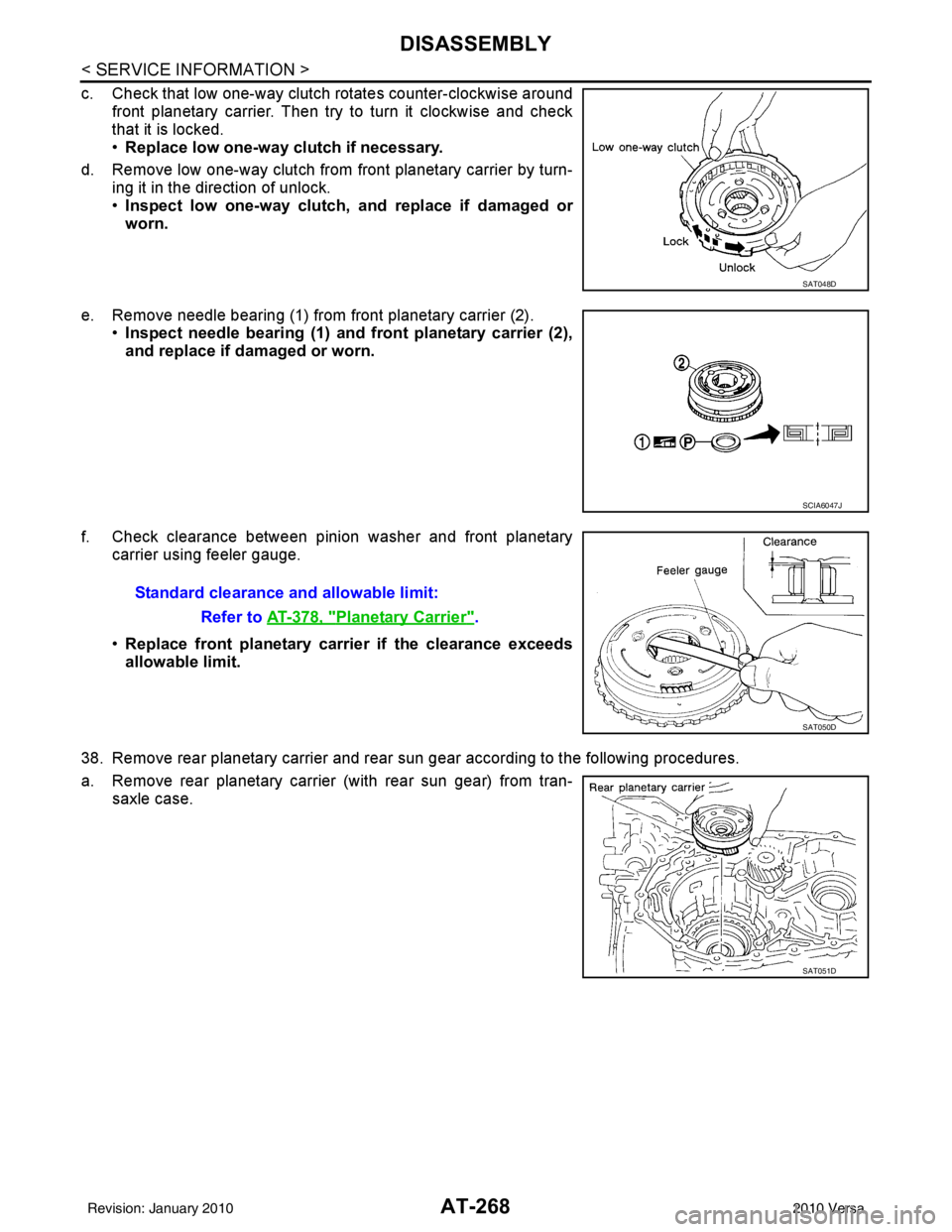
c. Check that low one-way clutch rotates counter-clockwise aroundfront planetary carrier. Then try to turn it clockwise and check
that it is locked.
•Replace low one-way clutch if necessary.
d. Remove low one-way clutch from front planetary carrier by turn- ing it in the direction of unlock.
•Inspect low one-way clutch, and replace if damaged or
worn.
e. Remove needle bearing (1) from front planetary carrier (2). •Inspect needle bearing (1) and front planetary carrier (2),
and replace if damaged or worn.
f. Check clearance between pinion washer and front planetary carrier using feeler gauge.
•Replace front planetary carrier if the clearance exceeds
allowable limit.
38. Remove rear planetary carrier and rear sun gear according to the following procedures.
a. Remove rear planetary carrier (with rear sun gear) from tran- saxle case.
SAT048D
SCIA6047J
Standard clearance and allowable limit:
Refer to AT-378, "
Planetary Carrier".
SAT050D
SAT051D
Revision: January 20102010 Versa
Page 286 of 3745
DISASSEMBLYAT-269
< SERVICE INFORMATION >
DE
F
G H
I
J
K L
M A
B
AT
N
O P
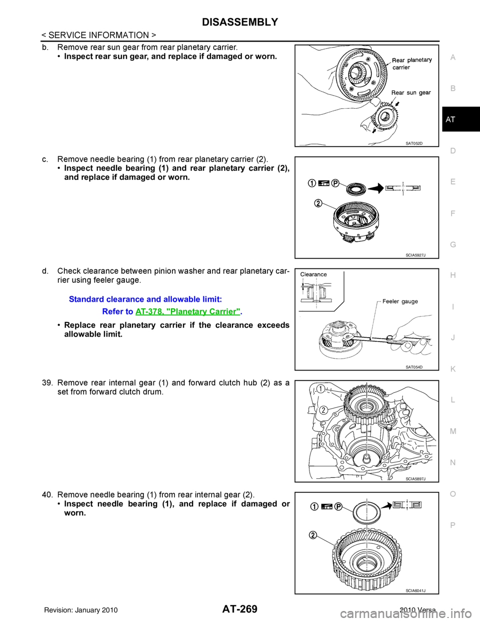
b. Remove rear sun gear from rear planetary carrier. •Inspect rear sun gear, and replace if damaged or worn.
c. Remove needle bearing (1) from rear planetary carrier (2). •Inspect needle bearing (1) and rear planetary carrier (2),
and replace if damaged or worn.
d. Check clearance between pinion washer and rear planetary car- rier using feeler gauge.
•Replace rear planetary carrier if the clearance exceeds
allowable limit.
39. Remove rear internal gear (1) and forward clutch hub (2) as a set from forward clutch drum.
40. Remove needle bearing (1) from rear internal gear (2). •Inspect needle bearing (1), and replace if damaged or
worn.
SAT052D
SCIA5927J
Standard clearance and allowable limit:
Refer to AT-378, "
Planetary Carrier".
SAT054D
SCIA5897J
SCIA6041J
Revision: January 20102010 Versa
Page 287 of 3745
AT-270
< SERVICE INFORMATION >
DISASSEMBLY
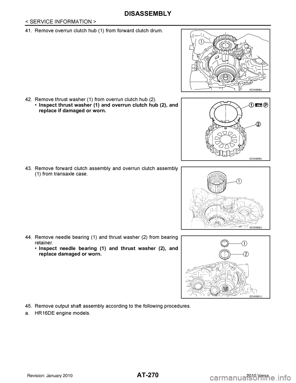
41. Remove overrun clutch hub (1) from forward clutch drum.
42. Remove thrust washer (1) from overrun clutch hub (2).•Inspect thrust washer (1) and overrun clutch hub (2), and
replace if damaged or worn.
43. Remove forward clutch assembly and overrun clutch assembly (1) from transaxle case.
44. Remove needle bearing (1) and thrust washer (2) from bearing retainer.
•Inspect needle bearing (1) and thrust washer (2), and
replace damaged or worn.
45. Remove output shaft assembly according to the following procedures.
a. HR16DE engine models.
SCIA5898J
SCIA5899J
SCIA5900J
SCIA5901J
Revision: January 20102010 Versa
Page 288 of 3745
DISASSEMBLYAT-271
< SERVICE INFORMATION >
DE
F
G H
I
J
K L
M A
B
AT
N
O P
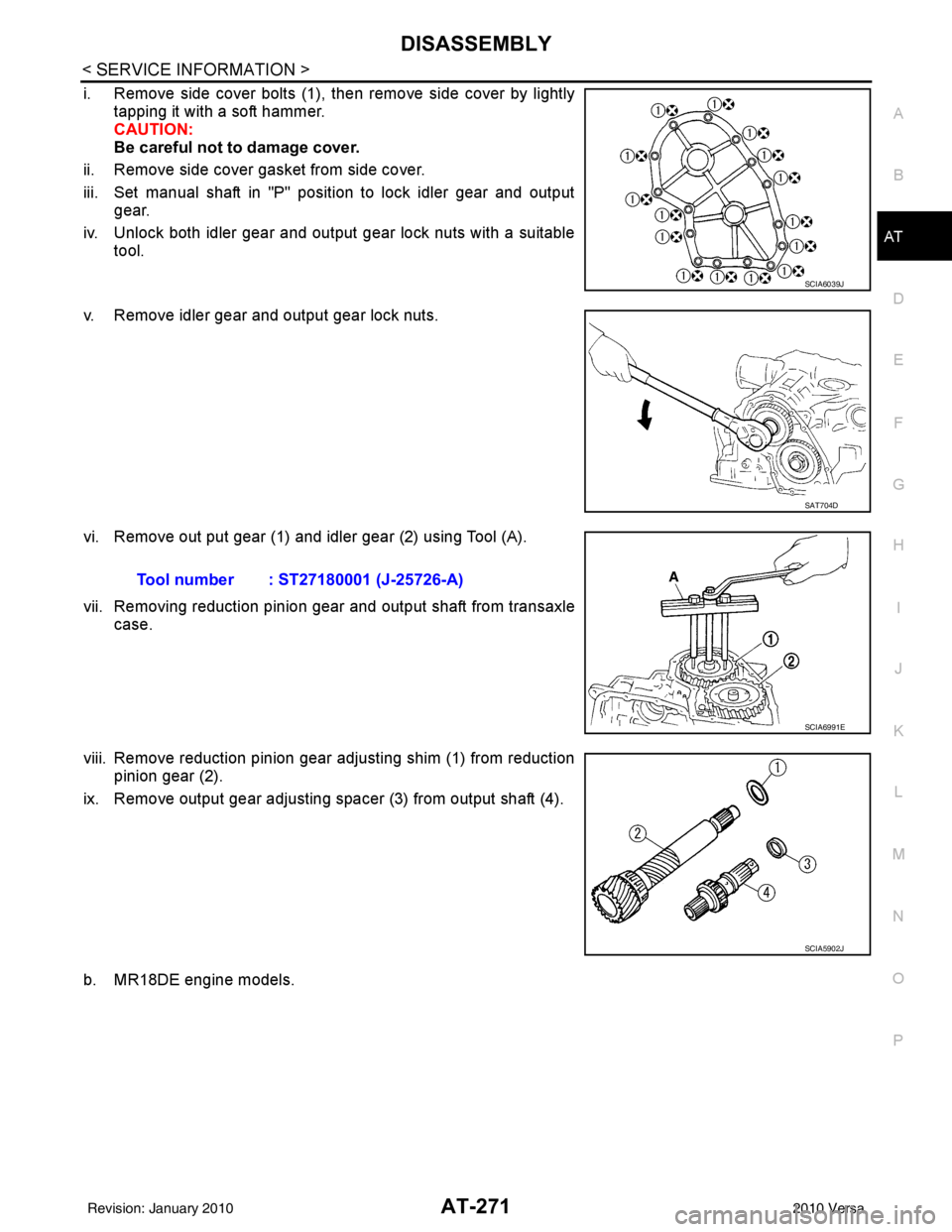
i. Remove side cover bolts (1), then remove side cover by lightly tapping it with a soft hammer.
CAUTION:
Be careful not to damage cover.
ii. Remove side cover gasket from side cover.
iii. Set manual shaft in "P" position to lock idler gear and output gear.
iv. Unlock both idler gear and output gear lock nuts with a suitable tool.
v. Remove idler gear and output gear lock nuts.
vi. Remove out put gear (1) and idler gear (2) using Tool (A).
vii. Removing reduction pinion gear and output shaft from transaxle case.
viii. Remove reduction pinion gear adjusting shim (1) from reduction pinion gear (2).
ix. Remove output gear adjusting spacer (3) from output shaft (4).
b. MR18DE engine models.
SCIA6039J
SAT704D
Tool number : ST27180001 (J-25726-A)
SCIA6991E
SCIA5902J
Revision: January 20102010 Versa
Page 289 of 3745
AT-272
< SERVICE INFORMATION >
DISASSEMBLY
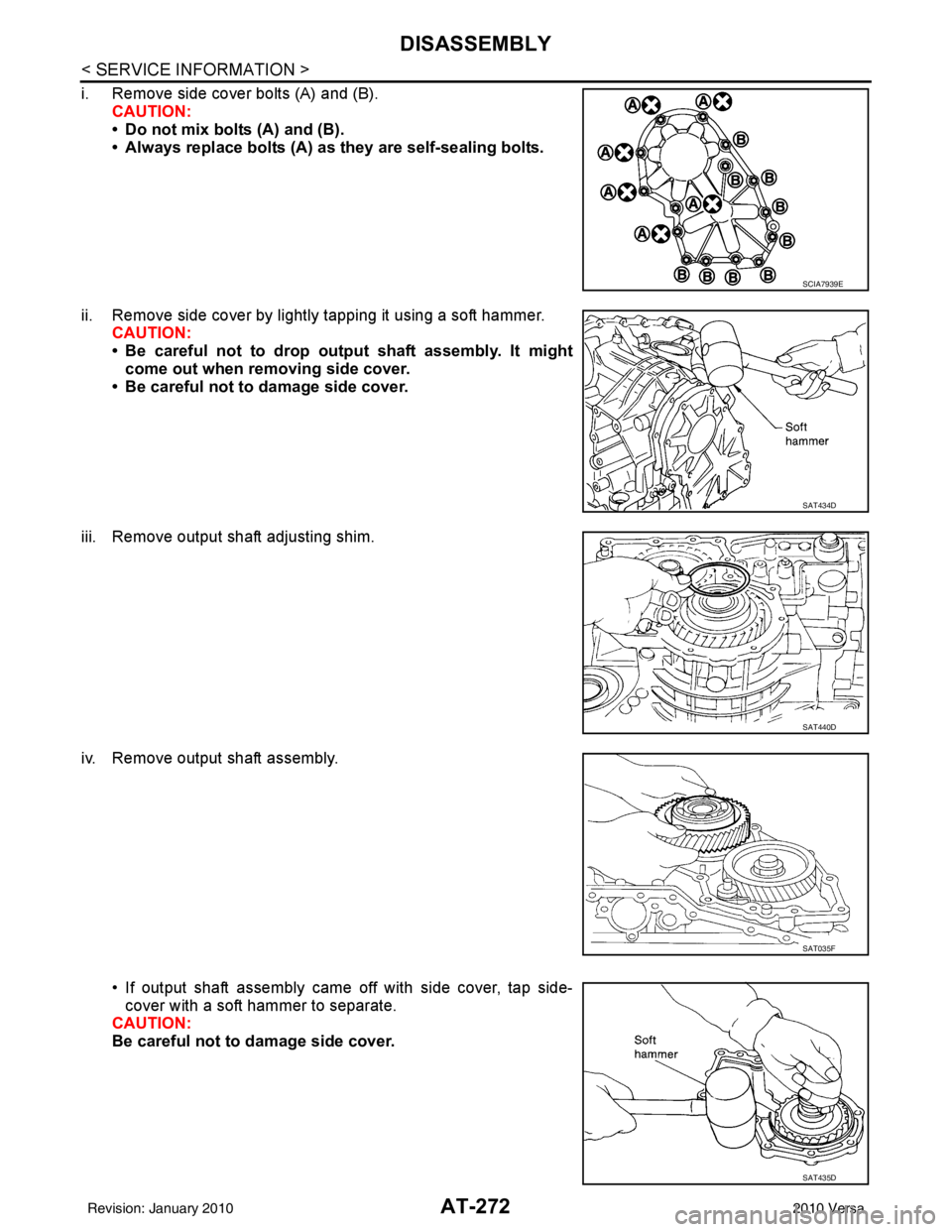
i. Remove side cover bolts (A) and (B).CAUTION:
• Do not mix bolts (A) and (B).
• Always replace bolts (A) as they are self-sealing bolts.
ii. Remove side cover by lightly tapping it using a soft hammer. CAUTION:
• Be careful not to drop output shaft assembly. It might
come out when removing side cover.
• Be careful not to damage side cover.
iii. Remove output shaft adjusting shim.
iv. Remove output shaft assembly.
• If output shaft assembly came off with side cover, tap side-cover with a soft hammer to separate.
CAUTION:
Be careful not to damage side cover.
SCIA7939E
SAT434D
SAT440D
SAT035F
SAT435D
Revision: January 20102010 Versa
Page 290 of 3745
DISASSEMBLYAT-273
< SERVICE INFORMATION >
DE
F
G H
I
J
K L
M A
B
AT
N
O P
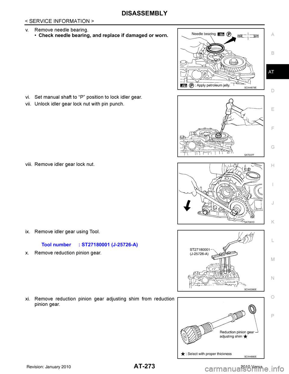
v. Remove needle bearing. •Check needle bearing, and replace if damaged or worn.
vi. Set manual shaft to “P” position to lock idler gear.
vii. Unlock idler gear lock nut with pin punch.
viii. Remove idler gear lock nut.
ix. Remove idler gear using Tool.
x. Remove reduction pinion gear.
xi. Remove reduction pinion gear adjusting shim from reduction pinion gear.
SCIA4879E
SAT037F
SAT061D
Tool number : ST27180001 (J-25726-A)
SCIA5380E
SCIA4880E
Revision: January 20102010 Versa
Trending: Lan system, height adjustment, spare tire, transmission fluid, AUX, tires, refrigerant type
