NISSAN NAVARA 2005 Repair Workshop Manual
NAVARA 2005
NISSAN
NISSAN
https://www.carmanualsonline.info/img/5/57362/w960_57362-0.png
NISSAN NAVARA 2005 Repair Workshop Manual
Trending: lug pattern, ignition, center console, oil filter, coolant level, hood release, radiator cap
Page 2201 of 3171
LT-118
COMBINATION SWITCH
Combination Switch Inspection
EKS00P9Y
1.SYSTEM CHECK
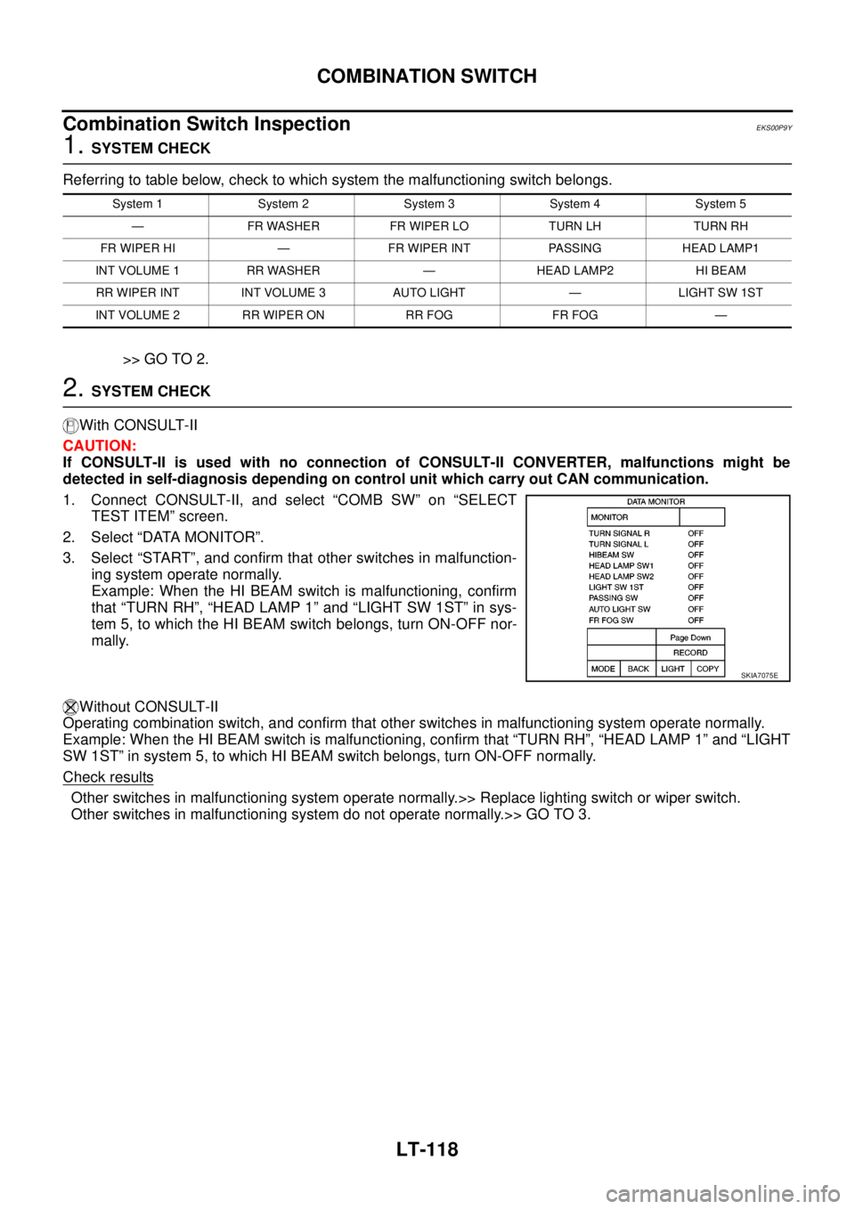
Referring to table below, check to which system the malfunctioning switch belongs.
>> GO TO 2.
2.SYSTEM CHECK
With CONSULT-II
CAUTION:
If CONSULT-II is used with no connection of CONSULT-II CONVERTER, malfunctions might be
detected in self-diagnosis depending on control unit which carry out CAN communication.
1. Connect CONSULT-II, and select “COMB SW” on “SELECT
TEST ITEM” screen.
2. Select “DATA MONITOR”.
3. Select “START”, and confirm that other switches in malfunction-
ing system operate normally.
Example: When the HI BEAM switch is malfunctioning, confirm
that “TURN RH”, “HEAD LAMP 1” and “LIGHT SW 1ST” in sys-
tem 5, to which the HI BEAM switch belongs, turn ON-OFF nor-
mally.
Without CONSULT-II
Operating combination switch, and confirm that other switches in malfunctioning system operate normally.
Example: When the HI BEAM switch is malfunctioning, confirm that “TURN RH”, “HEAD LAMP 1” and “LIGHT
SW 1ST” in system 5, to which HI BEAM switch belongs, turn ON-OFF normally.
Check results
Other switches in malfunctioning system operate normally.>> Replace lighting switch or wiper switch.
Other switches in malfunctioning system do not operate normally.>> GO TO 3.
System 1 System 2 System 3 System 4 System 5
— FR WASHER FR WIPER LO TURN LH TURN RH
FR WIPER HI — FR WIPER INT PASSING HEAD LAMP1
INT VOLUME 1 RR WASHER — HEAD LAMP2 HI BEAM
RR WIPER INT INT VOLUME 3 AUTO LIGHT — LIGHT SW 1ST
INT VOLUME 2 RR WIPER ON RR FOG FR FOG —
SKIA7075E
Page 2202 of 3171
COMBINATION SWITCH
LT-119
C
D
E
F
G
H
I
J
L
MA
B
LT
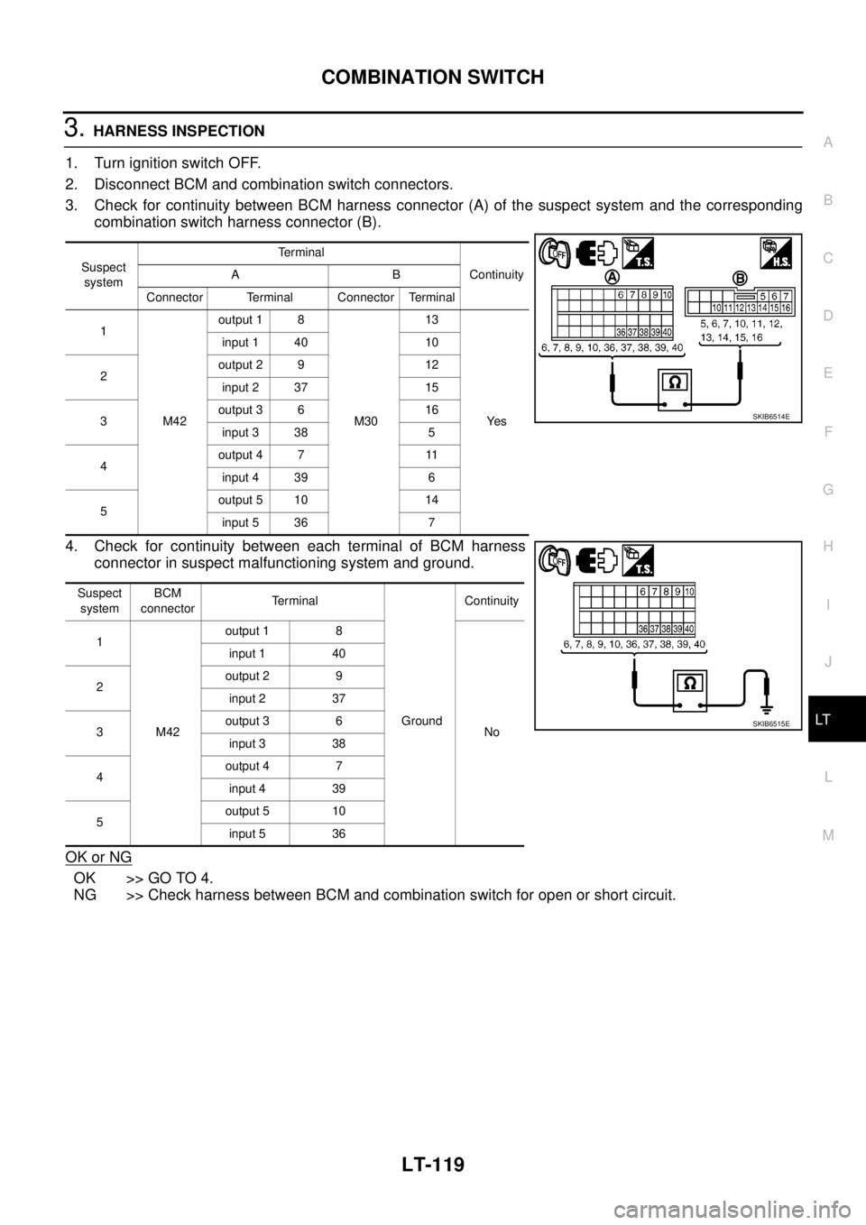
3.HARNESS INSPECTION
1. Turn ignition switch OFF.
2. Disconnect BCM and combination switch connectors.
3. Check for continuity between BCM harness connector (A) of the suspect system and the corresponding
combination switch harness connector (B).
4. Check for continuity between each terminal of BCM harness
connector in suspect malfunctioning system and ground.
OK or NG
OK >> GO TO 4.
NG >> Check harness between BCM and combination switch for open or short circuit.
Suspect
systemTerminal
Continuity AB
Connector Terminal Connector Terminal
1
M42output 1 8
M3013
Ye s input 1 40 10
2output 2 9 12
input 2 37 15
3output 3 6 16
input 3 38 5
4output 4 7 11
input 4 39 6
5output 5 10 14
input 5 36 7
Suspect
systemBCM
connectorTerminal
GroundContinuity
1
M42output 1 8
No input 1 40
2output 2 9
input 2 37
3output 3 6
input 3 38
4output 4 7
input 4 39
5output 5 10
input 5 36
SKIB6514E
SKIB6515E
Page 2203 of 3171
LT-120
COMBINATION SWITCH
4.BCM OUTPUT TERMINAL INSPECTION
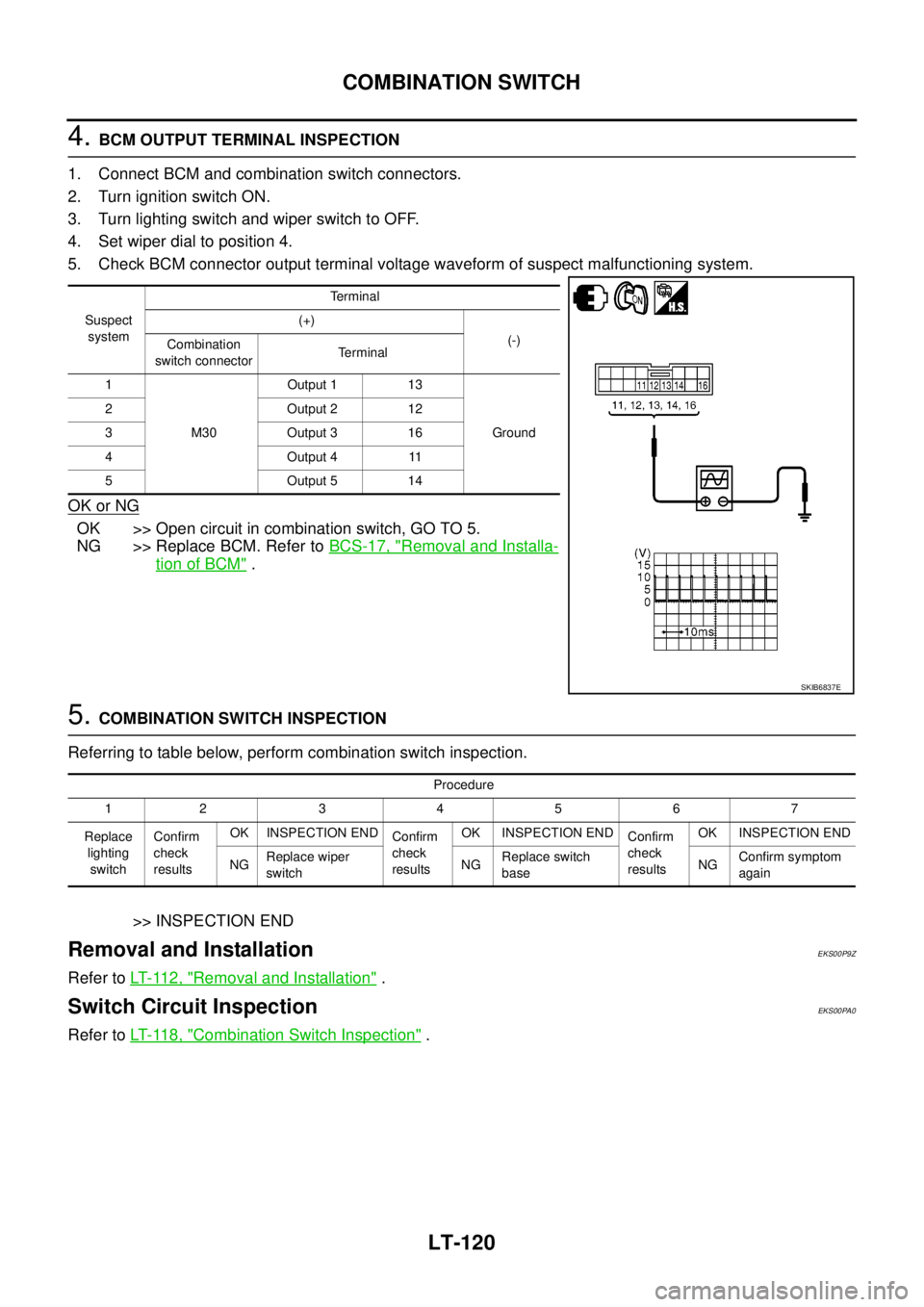
1. Connect BCM and combination switch connectors.
2. Turn ignition switch ON.
3. Turn lighting switch and wiper switch to OFF.
4. Set wiper dial to position 4.
5. Check BCM connector output terminal voltage waveform of suspect malfunctioning system.
OK or NG
OK >> Open circuit in combination switch, GO TO 5.
NG >> Replace BCM. Refer toBCS-17, "
Removal and Installa-
tion of BCM".
5.COMBINATION SWITCH INSPECTION
Referring to table below, perform combination switch inspection.
>> INSPECTION END
Removal and InstallationEKS00P9Z
Refer toLT- 11 2 , "Removal and Installation".
Switch Circuit InspectionEKS00PA0
Refer toLT- 11 8 , "Combination Switch Inspection".
Suspect
systemTerminal
(+)
(-)
Combination
switch connectorTerminal
1
M30Output 1 13
Ground 2 Output 2 12
3 Output 3 16
4Output411
5 Output 5 14
SKIB6837E
Procedure
12 34567
Replace
lighting
switchConfirm
check
resultsOK INSPECTION END
Confirm
check
resultsOK INSPECTION END
Confirm
check
resultsOK INSPECTION END
NGReplace wiper
switchNGReplace switch
baseNGConfirm symptom
again
Page 2204 of 3171
STOP LAMP
LT-121
C
D
E
F
G
H
I
J
L
MA
B
LT
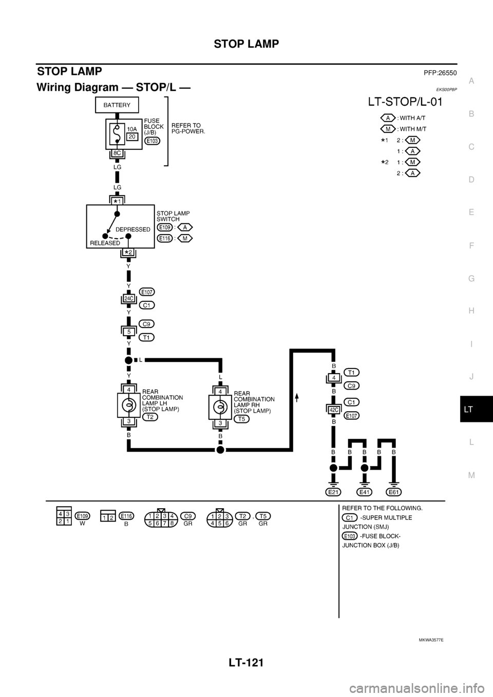
STOP LAMPPFP:26550
Wiring Diagram — STOP/L —EKS00P8P
MKWA3577E
Page 2205 of 3171
LT-122
STOP LAMP
Bulb Replacement
EKS00Q8A
Refer toLT- 1 4 3 , "Bulb Replacement".
Removal and InstallationEKS00Q8B
Refer toLT- 1 4 4 , "Removal and Installation".
Page 2206 of 3171
BACK-UP LAMP
LT-123
C
D
E
F
G
H
I
J
L
MA
B
LT
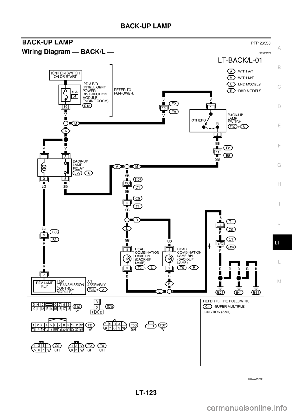
BACK-UP LAMPPFP:26550
Wiring Diagram — BACK/L —EKS00P8S
MKWA3578E
Page 2207 of 3171
LT-124
BACK-UP LAMP
Bulb Replacement
EKS00P8T
Refer toLT- 1 4 3 , "Bulb Replacement".
Removal and InstallationEKS00P8U
Refer toLT- 1 4 4 , "Removal and Installation".
Page 2208 of 3171
PARKING, LICENSE PLATE AND TAIL LAMPS
LT-125
C
D
E
F
G
H
I
J
L
MA
B
LT
PARKING, LICENSE PLATE AND TAIL LAMPSPFP:26550
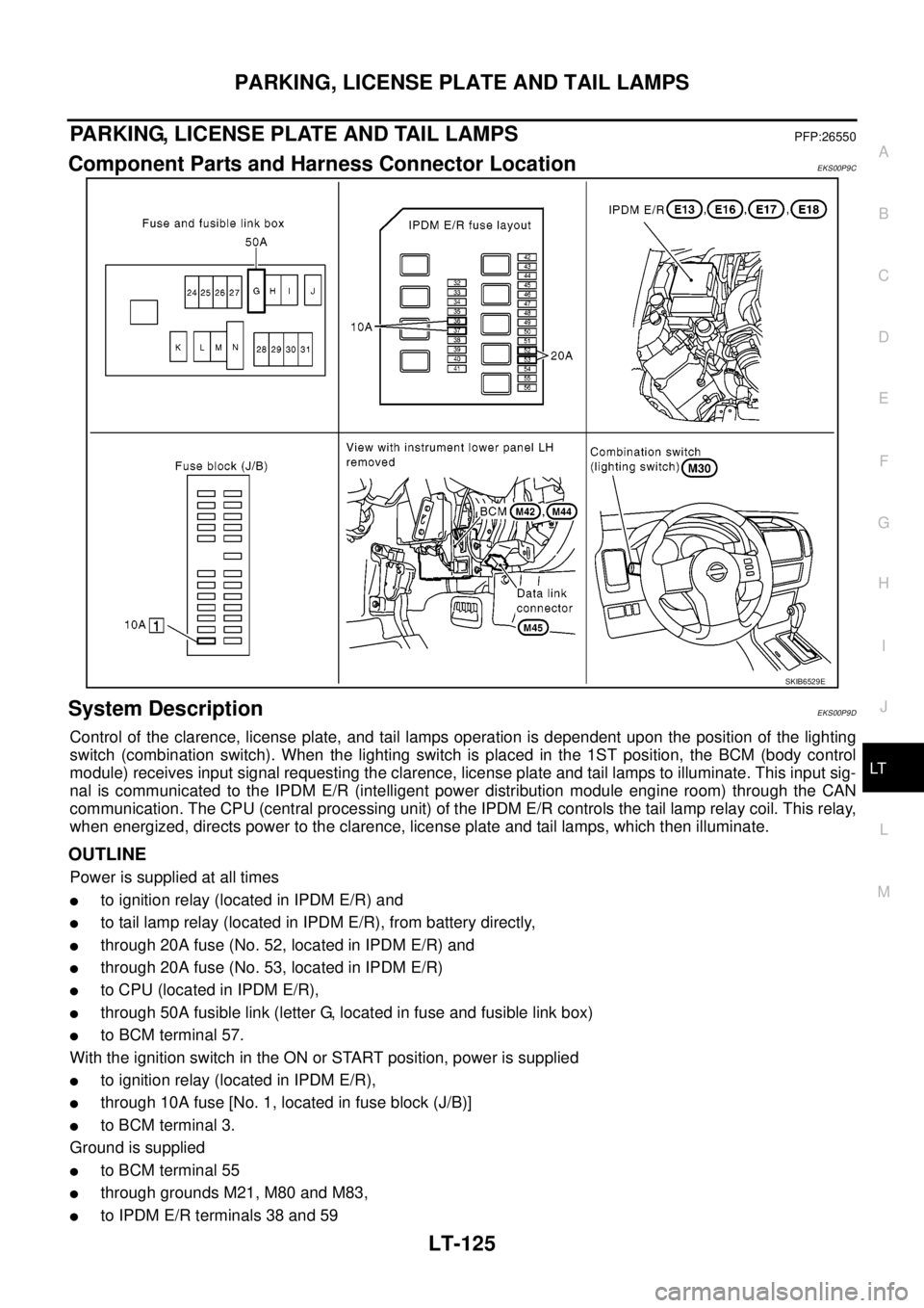
Component Parts and Harness Connector LocationEKS00P9C
System DescriptionEKS00P9D
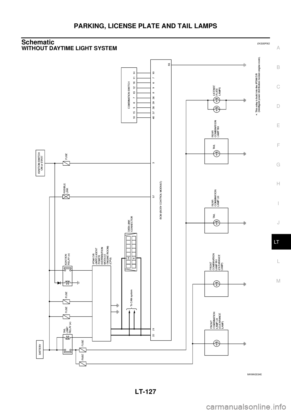
Control of the clarence, license plate, and tail lamps operation is dependent upon the position of the lighting
switch (combination switch). When the lighting switch is placed in the 1ST position, the BCM (body control
module) receives input signal requesting the clarence, license plate and tail lamps to illuminate. This input sig-
nal is communicated to the IPDM E/R (intelligent power distribution module engine room) through the CAN
communication. The CPU (central processing unit) of the IPDM E/R controls the tail lamp relay coil. This relay,
when energized, directs power to the clarence, license plate and tail lamps, which then illuminate.
OUTLINE
Power is supplied at all times
lto ignition relay (located in IPDM E/R) and
lto tail lamp relay (located in IPDM E/R), from battery directly,
lthrough 20A fuse (No. 52, located in IPDM E/R) and
lthrough 20A fuse (No. 53, located in IPDM E/R)
lto CPU (located in IPDM E/R),
lthrough 50A fusible link (letter G, located in fuse and fusible link box)
lto BCM terminal 57.
With the ignition switch in the ON or START position, power is supplied
lto ignition relay (located in IPDM E/R),
lthrough 10A fuse [No. 1, located in fuse block (J/B)]
lto BCM terminal 3.
Ground is supplied
lto BCM terminal 55
lthrough grounds M21, M80 and M83,
lto IPDM E/R terminals 38 and 59
SKIB6529E
Page 2209 of 3171

LT-126
PARKING, LICENSE PLATE AND TAIL LAMPS
lthrough grounds E21, E41 and E61.
OPERATION BY LIGHTING SWITCH
With the lighting switch in the 1ST position, 2ND position or AUTO position (when the auto light system is acti-
vated), the BCM receives input signal requesting the clarence, license plate and tail lamps to illuminate. This
input signal is communicated to the IPDM E/R through the CAN communication. The CPU in the IPDM E/R
controls the tail lamp relay coil, which when energized, directs power
lthrough IPDM E/R terminal 28
lto front combination lamp LH terminal 1,
lthrough IPDM E/R terminal 49
lto front combination lamp RH terminal 1,
lthrough IPDM E/R terminal 57
lto rear combination lamp RH and LH terminals 1 and
lto license plate lamp RH and LH terminals 1.
Ground is supplied
lto front combination lamp RH and LH terminals 2
lto rear combination lamp RH and LH terminals 3 and
lto license plate lamp RH and LH terminals 2
lthrough grounds E21, E41 and E61.
With power and ground supplied, the clarence, license plate and tail lamps illuminate.
COMBINATION SWITCH READING FUNCTION
Refer toBCS-3, "COMBINATION SWITCH READING FUNCTION".
CAN Communication System DescriptionEKS00P9F
Refer toLAN-23, "CAN COMMUNICATION".
Page 2210 of 3171
PARKING, LICENSE PLATE AND TAIL LAMPS
LT-127
C
D
E
F
G
H
I
J
L
MA
B
LT
SchematicEKS00P9G
WITHOUT DAYTIME LIGHT SYSTEM
MKWA3034E
Trending: length, bolt pattern, automatic transmission fluid, service reset, AUX, alternator, gas mileage

