NISSAN NAVARA 2005 Repair Workshop Manual
Manufacturer: NISSAN, Model Year: 2005, Model line: NAVARA, Model: NISSAN NAVARA 2005Pages: 3171, PDF Size: 49.59 MB
Page 2221 of 3171
LT-138
PARKING, LICENSE PLATE AND TAIL LAMPS
Clarence, License Plate and Tail Lamps Do Not Illuminate
EKS00P9Q
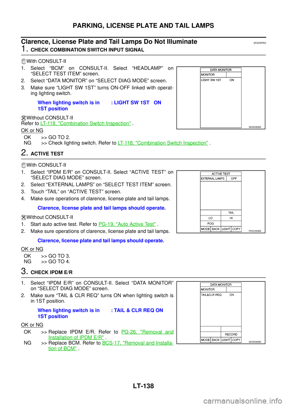
1.CHECK COMBINATION SWITCH INPUT SIGNAL
With CONSULT-II
1. Select “BCM” on CONSULT-II. Select “HEADLAMP” on
“SELECT TEST ITEM” screen.
2. Select “DATA MONITOR” on “SELECT DIAG MODE” screen.
3. Make sure “LIGHT SW 1ST” turns ON-OFF linked with operat-
ing lighting switch.
Without CONSULT-II
Refer toLT- 11 8 , "
Combination Switch Inspection".
OK or NG
OK >> GO TO 2.
NG >> Check lighting switch. Refer toLT- 11 8 , "
Combination Switch Inspection".
2.ACTIVE TEST
With CONSULT-II
1. Select “IPDM E/R” on CONSULT-II. Select “ACTIVE TEST” on
“SELECT DIAG MODE” screen.
2. Select “EXTERNAL LAMPS” on “SELECT TEST ITEM” screen.
3. Touch “TAIL” on “ACTIVE TEST” screen.
4. Make sure operations of clarence, license plate and tail lamps.
Without CONSULT-II
1. Start auto active test. Refer toPG-19, "
Auto Active Test".
2. Make sure operations of clarence, license plate and tail lamps.
OK or NG
OK >> GO TO 3.
NG >> GO TO 4.
3.CHECK IPDM E/R
1. Select “IPDM E/R” on CONSULT-II. Select “DATA MONITOR”
on “SELECT DIAG MODE” screen.
2. Make sure “TAIL & CLR REQ” turns ON when lighting switch is
in 1ST position.
OK or NG
OK >> Replace IPDM E/R. Refer toPG-26, "Removal and
Installation of IPDM E/R".
NG >> Replace BCM. Refer toBCS-17, "
Removal and Installa-
tion of BCM". When lighting switch is in
1ST position: LIGHT SW 1ST ON
SKIA5956E
Clarence, license plate and tail lamps should operate.
Clarence, license plate and tail lamps should operate.
PKIC0936E
When lighting switch is in
1ST position: TAIL & CLR REQ ON
SKIA5958E
Page 2222 of 3171
PARKING, LICENSE PLATE AND TAIL LAMPS
LT-139
C
D
E
F
G
H
I
J
L
MA
B
LT
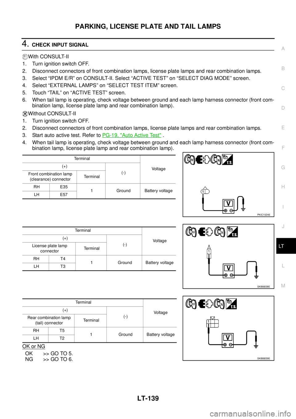
4.CHECK INPUT SIGNAL
With CONSULT-II
1. Turn ignition switch OFF.
2. Disconnect connectors of front combination lamps, license plate lamps and rear combination lamps.
3. Select “IPDM E/R” on CONSULT-II. Select “ACTIVE TEST” on “SELECT DIAG MODE” screen.
4. Select “EXTERNAL LAMPS” on “SELECT TEST ITEM” screen.
5. Touch “TAIL” on “ACTIVE TEST” screen.
6. When tail lamp is operating, check voltage between ground and each lamp harness connector (front com-
bination lamp, license plate lamp and rear combination lamp).
Without CONSULT-II
1. Turn ignition switch OFF.
2. Disconnect connectors of front combination lamps, license plate lamps and rear combination lamps.
3. Start auto active test. Refer toPG-19, "
Auto Active Test".
4. When tail lamp is operating, check voltage between ground and each lamp harness connector (front com-
bination lamp, license plate lamp and rear combination lamp).
OK or NG
OK >> GO TO 5.
NG >> GO TO 6.
Terminal
Voltage (+)
(-)
Front combination lamp
(clearance) connectorTerminal
RH E35
1 Ground Battery voltage
LH E57
PKIC1024E
Terminal
Vo l ta g e (+)
(-)
License plate lamp
connectorTerminal
RH T4
1 Ground Battery voltage
LH T3
SKIB6838E
Terminal
Voltage (+)
(-)
Rear combination lamp
(tail) connectorTe r m i n a l
RH T5
1 Ground Battery voltage
LH T2
SKIB6839E
Page 2223 of 3171
LT-140
PARKING, LICENSE PLATE AND TAIL LAMPS
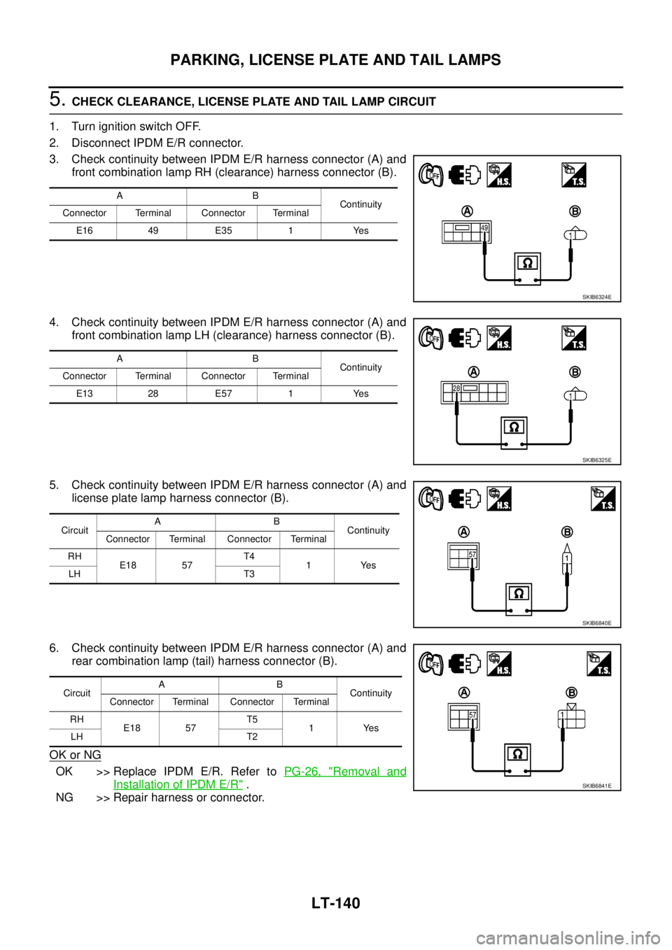
5.CHECK CLEARANCE, LICENSE PLATE AND TAIL LAMP CIRCUIT
1. Turn ignition switch OFF.
2. Disconnect IPDM E/R connector.
3. Check continuity between IPDM E/R harness connector (A) and
front combination lamp RH (clearance) harness connector (B).
4. Check continuity between IPDM E/R harness connector (A) and
front combination lamp LH (clearance) harness connector (B).
5. Check continuity between IPDM E/R harness connector (A) and
license plate lamp harness connector (B).
6. Check continuity between IPDM E/R harness connector (A) and
rear combination lamp (tail) harness connector (B).
OK or NG
OK >> Replace IPDM E/R. Refer toPG-26, "Removal and
Installation of IPDM E/R".
NG >> Repair harness or connector.
AB
Continuity
Connector Terminal Connector Terminal
E16 49 E35 1 Yes
SKIB6324E
AB
Continuity
Connector Terminal Connector Terminal
E13 28 E57 1 Yes
SKIB6325E
CircuitAB
Continuity
Connector Terminal Connector Terminal
RH
E18 57T4
1Yes
LH T3
SKIB6840E
CircuitAB
Continuity
Connector Terminal Connector Terminal
RH
E18 57T5
1Yes
LH T2
SKIB6841E
Page 2224 of 3171
PARKING, LICENSE PLATE AND TAIL LAMPS
LT-141
C
D
E
F
G
H
I
J
L
MA
B
LT
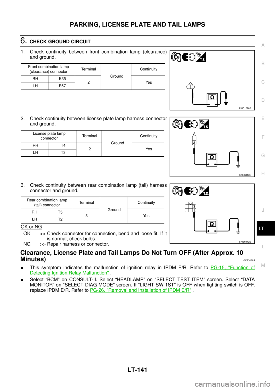
6.CHECK GROUND CIRCUIT
1. Check continuity between front combination lamp (clearance)
and ground.
2. Check continuity between license plate lamp harness connector
and ground.
3. Check continuity between rear combination lamp (tail) harness
connector and ground.
OK or NG
OK >> Check connector for connection, bend and loose fit. If it
is normal, check bulbs.
NG >> Repair harness or connector.
Clearance, License Plate and Tail Lamps Do Not Turn OFF (After Approx. 10
Minutes)
EKS00P9S
lThis symptom indicates the malfunction of ignition relay in IPDM E/R. Refer toPG-15, "Function of
Detecting Ignition Relay Malfunction".
lSelect “BCM” on CONSULT-II. Select “HEADLAMP” on “SELECT TEST ITEM” screen. Select “DATA
MONITOR” on “SELECT DIAG MODE” screen. If “LIGHT SW 1ST” is OFF when lighting switch is OFF,
replace IPDM E/R. Refer toPG-26, "
Removal and Installation of IPDM E/R".
Front combination lamp
(clearance) connectorTerminal
GroundContinuity
RH E35
2Yes
LH E57
PKIC1028E
License plate lamp
connectorTerminal
GroundContinuity
RH T4
2Yes
LH T3
SKIB6842E
Rear combination lamp
(tail) connectorTerminal
GroundContinuity
RH T5
3Yes
LH T2
SKIB6843E
Page 2225 of 3171

LT-142
PARKING, LICENSE PLATE AND TAIL LAMPS
Front Clearance Lamp
EKS00P9T
BULB REPLACEMENT
Refer toLT- 2 9 , "Bulb Replacement".
Ta i l L a m pEKS00P9U
BULB REPLACEMENT
Refer toLT- 1 4 3 , "Bulb Replacement".
Page 2226 of 3171
REAR COMBINATION LAMP
LT-143
C
D
E
F
G
H
I
J
L
MA
B
LT
REAR COMBINATION LAMPPFP:26554
Bulb ReplacementEKS00P90
REMOVAL
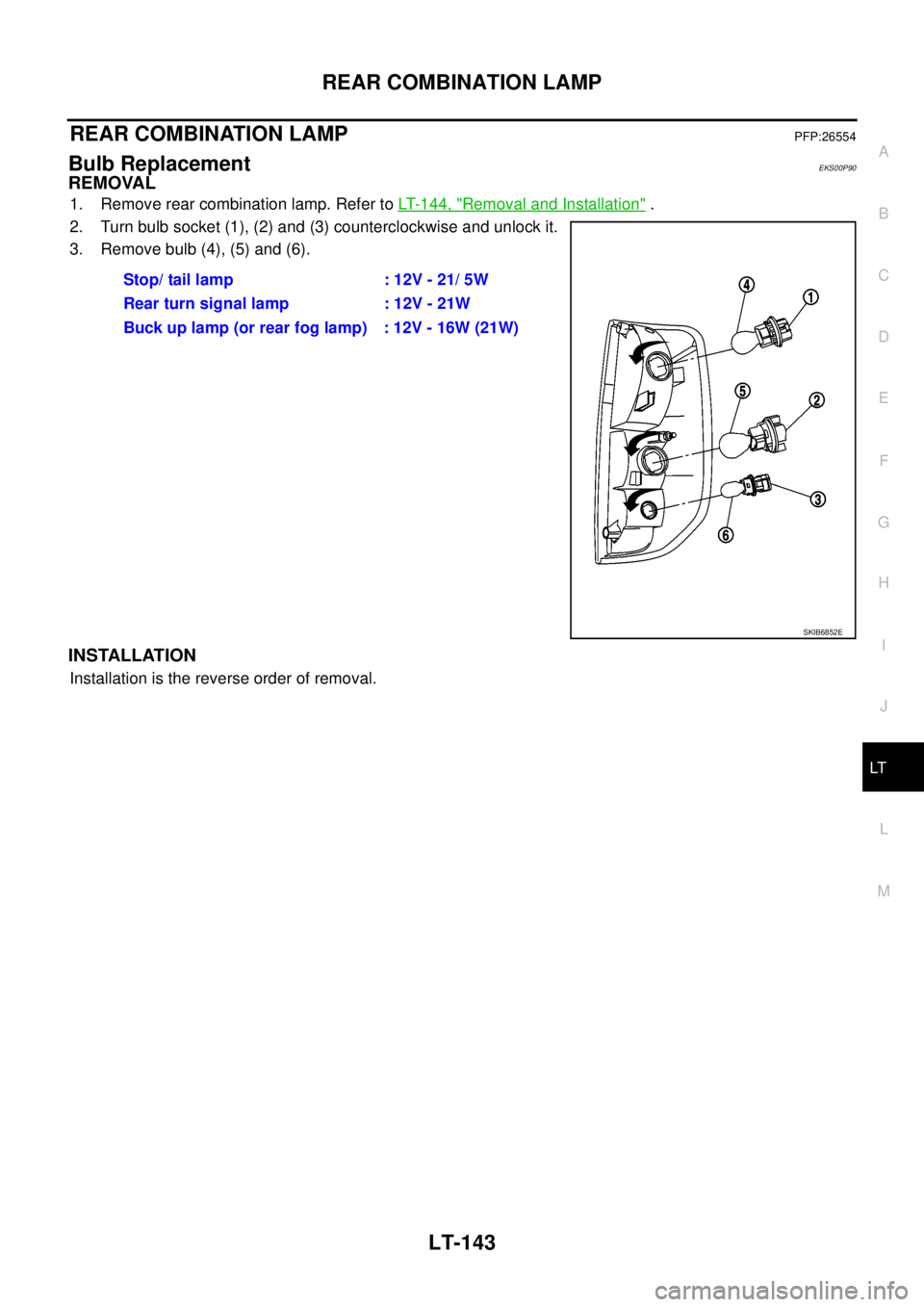
1. Remove rear combination lamp. Refer toLT- 1 4 4 , "Removal and Installation".
2. Turn bulb socket (1), (2) and (3) counterclockwise and unlock it.
3. Remove bulb (4), (5) and (6).
INSTALLATION
Installation is the reverse order of removal.Stop/taillamp :12V-21/5W
Rear turn signal lamp : 12V - 21W
Buck up lamp (or rear fog lamp) : 12V - 16W (21W)
SKIB6852E
Page 2227 of 3171
LT-144
REAR COMBINATION LAMP
Removal and Installation
EKS00P91
REMOVAL
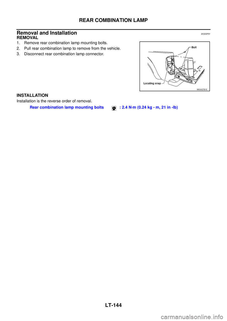
1. Remove rear combination lamp mounting bolts.
2. Pull rear combination lamp to remove from the vehicle.
3. Disconnect rear combination lamp connector.
INSTALLATION
Installation is the reverse order of removal.
WKIA3781E
Rear combination lamp mounting bolts : 2.4 N·m (0.24 kg - m, 21 in -lb)
Page 2228 of 3171
INTERIOR ROOM LAMP
LT-145
C
D
E
F
G
H
I
J
L
MA
B
LT
INTERIOR ROOM LAMPPFP:26410
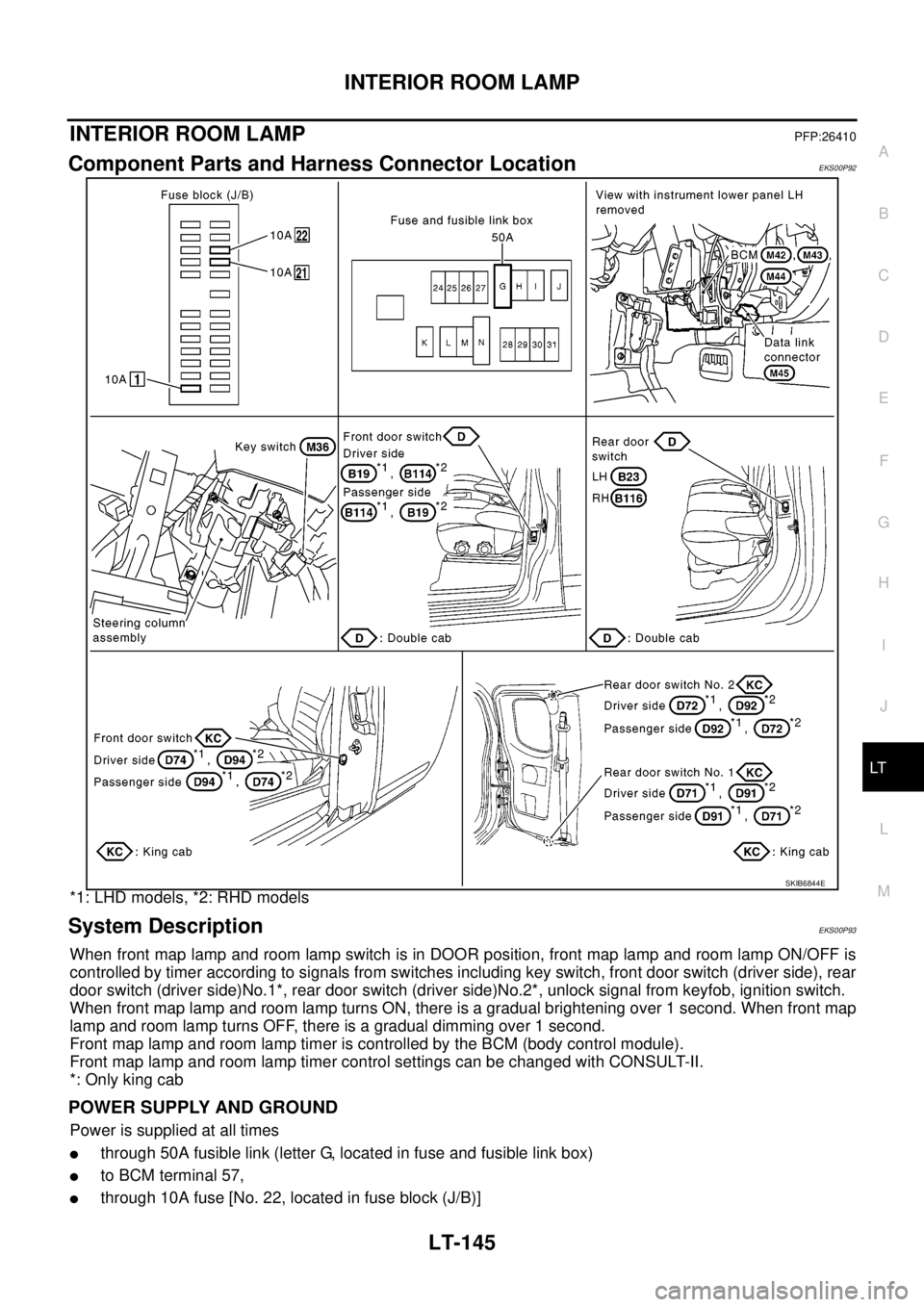
Component Parts and Harness Connector LocationEKS00P92
*1: LHD models, *2: RHD models
System DescriptionEKS00P93
When front map lamp and room lamp switch is in DOOR position, front map lamp and room lamp ON/OFF is
controlled by timer according to signals from switches including key switch, front door switch (driver side), rear
door switch (driver side)No.1*, rear door switch (driver side)No.2*, unlock signal from keyfob, ignition switch.
When front map lamp and room lamp turns ON, there is a gradual brightening over 1 second. When front map
lamp and room lamp turns OFF, there is a gradual dimming over 1 second.
Front map lamp and room lamp timer is controlled by the BCM (body control module).
Front map lamp and room lamp timer control settings can be changed with CONSULT-II.
*: Only king cab
POWER SUPPLY AND GROUND
Power is supplied at all times
lthrough 50A fusible link (letter G, located in fuse and fusible link box)
lto BCM terminal 57,
lthrough 10A fuse [No. 22, located in fuse block (J/B)]
SKIB6844E
Page 2229 of 3171
![NISSAN NAVARA 2005 Repair Workshop Manual LT-146
INTERIOR ROOM LAMP
lto key switch terminal 2,
lthrough 10A fuse [No. 21, located in fuse block (J/B)]
lto BCM terminal 41.
When key is inserted in key switch, power is supplied
lthrough the key NISSAN NAVARA 2005 Repair Workshop Manual LT-146
INTERIOR ROOM LAMP
lto key switch terminal 2,
lthrough 10A fuse [No. 21, located in fuse block (J/B)]
lto BCM terminal 41.
When key is inserted in key switch, power is supplied
lthrough the key](/img/5/57362/w960_57362-2228.png)
LT-146
INTERIOR ROOM LAMP
lto key switch terminal 2,
lthrough 10A fuse [No. 21, located in fuse block (J/B)]
lto BCM terminal 41.
When key is inserted in key switch, power is supplied
lthrough the key switch terminal 1
lto BCM terminal 5.
With ignition switch in the ON or START position, power is supplied
lthrough 10A fuse [No. 1, located in fuse and block (J/B)]
lto BCM terminal 3.
Ground is supplied
lto BCM terminal 55
lthrough grounds M21, M80 and M83.
When front driver side door is opened, ground is supplied (double cab)
lto BCM terminal 15
lthrough front door switch driver side terminal 2
lthrough case ground of front door switch driver side.
When front passenger side door is opened, ground is supplied (double cab)
lto BCM terminal 14
lthrough front door switch passenger side terminal 2
lthrough case ground of front door switch passenger side.
When rear door LH is opened, ground is supplied (double cab)
lto BCM terminal 16
lthrough rear door switch LH terminal 2
lthrough case ground of rear door switch LH.
When rear door RH is opened, ground is supplied (double cab)
lto BCM terminal 12
lthrough rear door switch RH terminal 2
lthrough case ground of rear door switch RH.
When front driver side door is opened, ground is supplied (king cab)
lto BCM terminal 15
lthrough front door switch (driver side) terminal 2
lthrough front door switch (driver side) terminal 3
lthrough grounds B9 and B25 (LHD models)
lthrough grounds B106 and B121 (RHD models).
When front passenger side door is opened, ground is supplied (king cab)
lto BCM terminal 14
lthrough front door switch (passenger side) terminal 2
lthrough front door switch (passenger side) terminal 3
lthrough grounds B9 and B25 (LHD models)
lthrough grounds B106 and B121 (RHD models).
When rear door (driver side) is opened, ground is supplied (king cab)
lto BCM terminal 15
lthrough rear door switch (driver side) No.1 and No.2 terminals 1
lthrough rear door switch (driver side) No.1 and No.2 terminals 2
lthrough grounds B9 and B25 (LHD models)
lthrough grounds B106 and B121 (RHD models).
When rear door (passenger side) is opened, ground is supplied (king cab)
lto BCM terminal 14
lthrough rear door switch (passenger side) No.1 and No.2 terminals 1
Page 2230 of 3171

INTERIOR ROOM LAMP
LT-147
C
D
E
F
G
H
I
J
L
MA
B
LT
lthrough rear door switch (passenger side) No.1 and No.2 terminals 2
lthrough grounds B9 and B25 (LHD models)
lthrough grounds B106 and B121 (RHD models).
When a signal is received by BCM, power is supplied
lthrough BCM terminal 42
lto key ring lamp terminal 1
lto front map lamp terminal 1 and
lto room lamp terminal 2.
SWITCH OPERATION
When front map lamp switch is ON, ground is supplied
lto front map lamp terminal 2
lthrough grounds M21, M80 and M83.
When room lamp switch is ON, ground is supplied through room lamp case ground.
ROOM LAMP TIMER OPERATION
When lamp switch is in DOOR position, and when all conditions below are met, BCM performs timer control
(maximum 30 seconds) for interior room lamp and map lamp ON/OFF.
Power is supplied
lthrough 10A fuse [No. 22, located in fuse block (J/B)]
lto key switch terminal 2.
Key is removed from ignition key cylinder (key switch OFF), power will not be supplied to BCM terminal 5.
At the time that driver's door is opened, BCM detects that driver's door is unlocked. It determines that room
lamp timer operation conditions are met, and turns the interior room lamps ON for 30 seconds.
Key is in ignition key cylinder (key switch ON), power is supplied
lthrough key switch terminal 1
lto BCM terminal 5.
When key is removed from key switch (key switch OFF), power supply to BCM terminal 5 is terminated. BCM
detects that key has been removed, determines that room lamp timer conditions are met, and turns the interior
room lamps ON for 30 seconds.
When driver's door opens®closes, and the key is not inserted in the key switch (key switch OFF), BCM ter-
minal 15 changes between 0V (door open)®12V (door closed). The BCM determines that conditions for
room lamp operation are met and turns the room lamp ON for 30 seconds.
Timer control is canceled under the following conditions.
lDriver's door is opened [front door switch (driver side)].
lIgnition switch ON.
lKeyfob
INTERIOR LAMP BATTERY SAVER CONTROL
If interior lamp is left ON, it will not be turned off even when door is closed.
BCM turns off interior lamp automatically to save battery 30 minutes after ignition switch is turned off.
BCM controls interior lamps listed below:
lFront map lamp
lRoom lamp
lKey ring lamp
After lamps turn OFF by the battery saver system, the lamps illuminate again when
lsignal received from keyfob or key cylinder is locked or unlocked,
ldoor is opened or closed,
lkey is removed from ignition key cylinder or inserted in ignition key cylinder.
Interior lamp battery saver control period can be changed by the function setting of CONSULT-II. Refer toLT-
158, "WORK SUPPORT".