NISSAN NAVARA 2005 Repair Workshop Manual
NAVARA 2005
NISSAN
NISSAN
https://www.carmanualsonline.info/img/5/57362/w960_57362-0.png
NISSAN NAVARA 2005 Repair Workshop Manual
Trending: roof, wheel torque, odometer, fuel tank capacity, air filter, height, fuse box diagram
Page 671 of 3171
POWER DOOR LOCK — SUPER LOCK —
BL-87
C
D
E
F
G
H
J
K
L
MA
B
BL
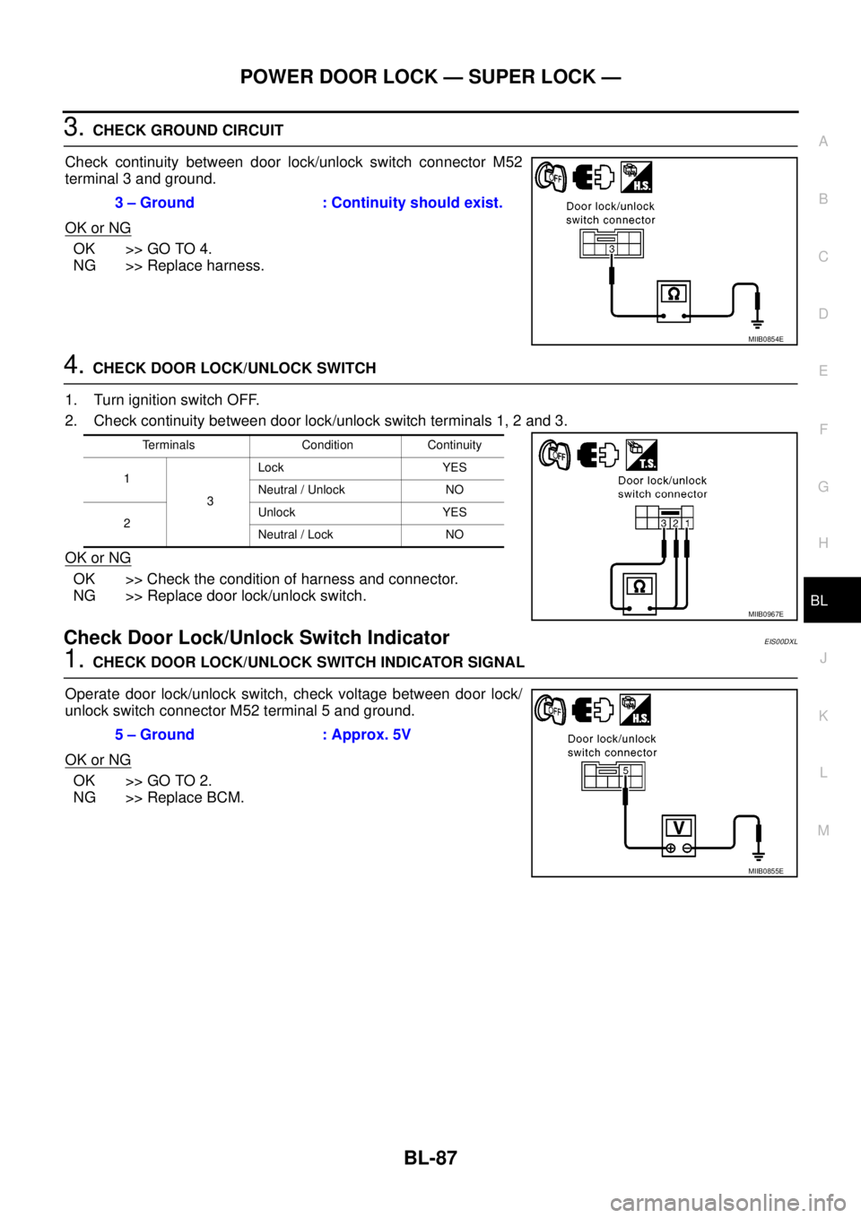
3.CHECK GROUND CIRCUIT
Check continuity between door lock/unlock switch connector M52
terminal 3 and ground.
OK or NG
OK >> GO TO 4.
NG >> Replace harness.
4.CHECK DOOR LOCK/UNLOCK SWITCH
1. Turn ignition switch OFF.
2. Check continuity between door lock/unlock switch terminals 1, 2 and 3.
OK or NG
OK >> Check the condition of harness and connector.
NG >> Replace door lock/unlock switch.
Check Door Lock/Unlock Switch IndicatorEIS00DXL
1.CHECK DOOR LOCK/UNLOCK SWITCH INDICATOR SIGNAL
Operate door lock/unlock switch, check voltage between door lock/
unlock switch connector M52 terminal 5 and ground.
OK or NG
OK >> GO TO 2.
NG >> Replace BCM.3 – Ground : Continuity should exist.
MIIB0854E
Terminals Condition Continuity
1
3Lock YES
Neutral / Unlock NO
2Unlock YES
Neutral / Lock NO
MIIB0967E
5 – Ground : Approx. 5V
MIIB0855E
Page 672 of 3171
BL-88
POWER DOOR LOCK — SUPER LOCK —
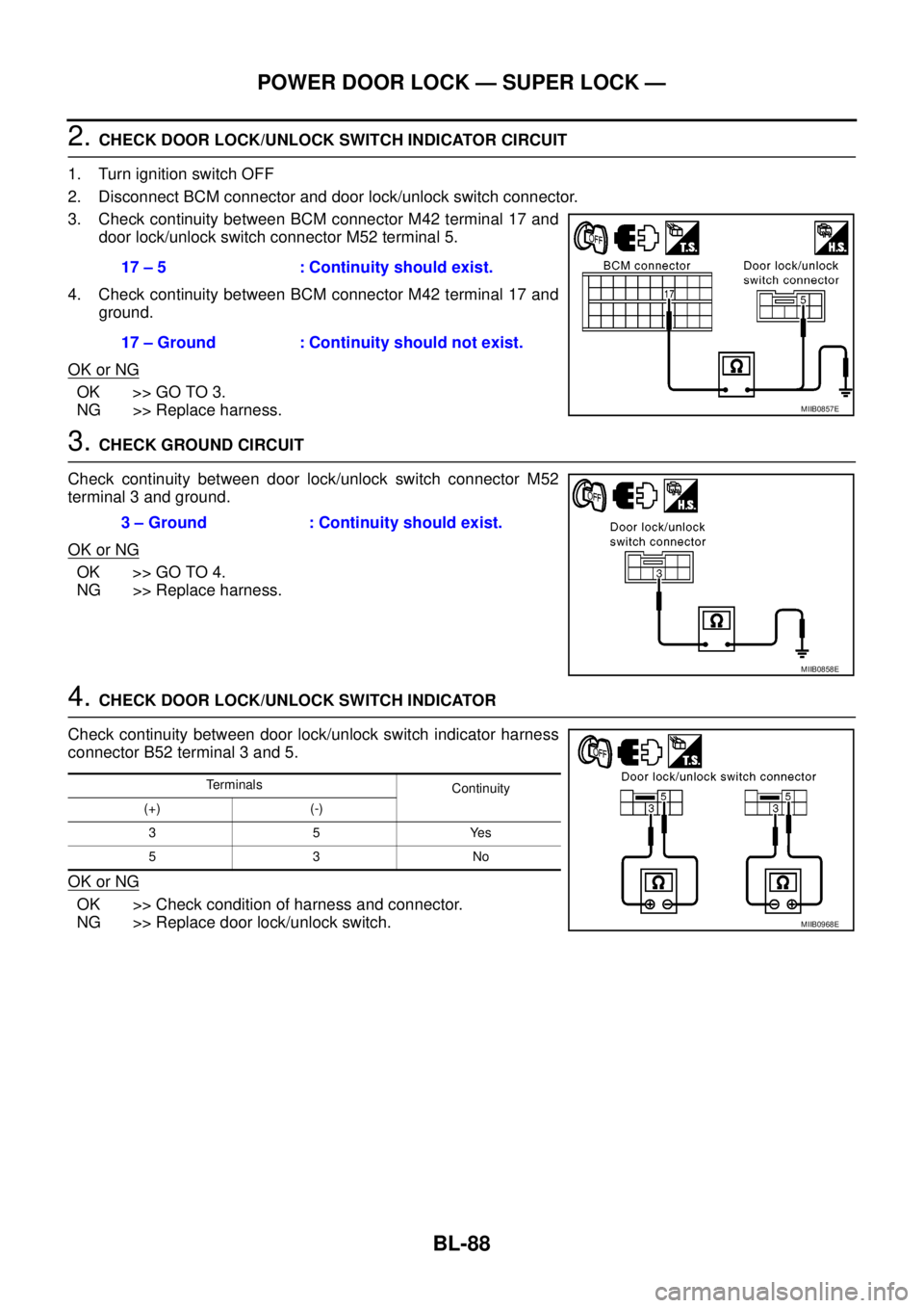
2.CHECK DOOR LOCK/UNLOCK SWITCH INDICATOR CIRCUIT
1. Turn ignition switch OFF
2. Disconnect BCM connector and door lock/unlock switch connector.
3. Check continuity between BCM connector M42 terminal 17 and
door lock/unlock switch connector M52 terminal 5.
4. Check continuity between BCM connector M42 terminal 17 and
ground.
OK or NG
OK >> GO TO 3.
NG >> Replace harness.
3.CHECK GROUND CIRCUIT
Check continuity between door lock/unlock switch connector M52
terminal 3 and ground.
OK or NG
OK >> GO TO 4.
NG >> Replace harness.
4.CHECK DOOR LOCK/UNLOCK SWITCH INDICATOR
Check continuity between door lock/unlock switch indicator harness
connector B52 terminal 3 and 5.
OK or NG
OK >> Check condition of harness and connector.
NG >> Replace door lock/unlock switch.17 – 5 : Continuity should exist.
17 – Ground : Continuity should not exist.
MIIB0857E
3 – Ground : Continuity should exist.
MIIB0858E
Terminals
Continuity
(+) (-)
35Yes
53No
MIIB0968E
Page 673 of 3171
MULTI-REMOTE CONTROL SYSTEM
BL-89
C
D
E
F
G
H
J
K
L
MA
B
BL
MULTI-REMOTE CONTROL SYSTEMPFP:25362
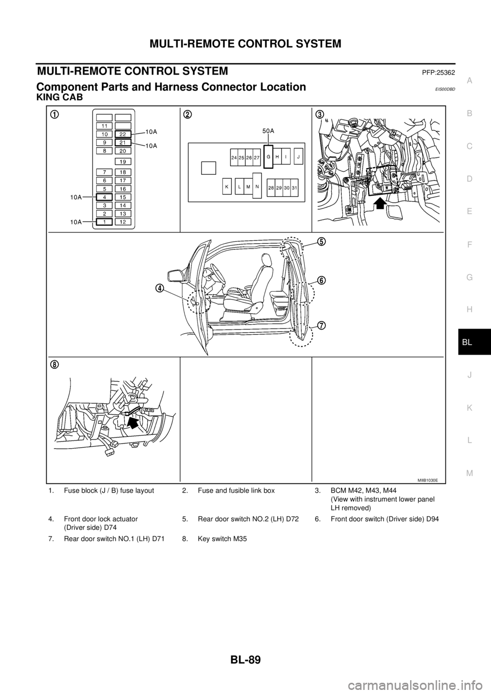
Component Parts and Harness Connector LocationEIS00DBD
KING CAB
1. Fuse block (J / B) fuse layout 2. Fuse and fusible link box 3. BCM M42, M43, M44
(View with instrument lower panel
LH removed)
4. Front door lock actuator
(Driver side) D745. Rear door switch NO.2 (LH) D72 6. Front door switch (Driver side) D94
7. Rear door switch NO.1 (LH) D71 8. Key switch M35
MIIB1030E
Page 674 of 3171
BL-90
MULTI-REMOTE CONTROL SYSTEM
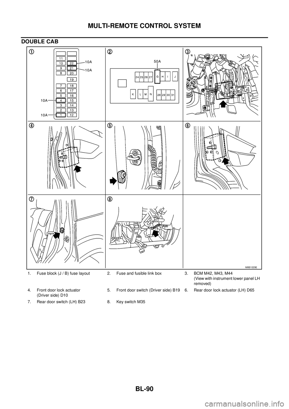
DOUBLE CAB
1. Fuse block (J / B) fuse layout 2. Fuse and fusible link box 3. BCM M42, M43, M44
(View with instrument lower panel LH
removed)
4. Front door lock actuator
(Driver side) D105. Front door switch (Driver side) B19 6. Rear door lock actuator (LH) D65
7. Rear door switch (LH) B23 8. Key switch M35
MIIB1029E
Page 675 of 3171

MULTI-REMOTE CONTROL SYSTEM
BL-91
C
D
E
F
G
H
J
K
L
MA
B
BL
System DescriptionEIS00DBE
INPUTS
Power is supplied at all times
lto BCM terminal 57
lthrough 50A fusible link (letterG, located in the fuse and fusible link box).
lto BCM terminal 41
lthrough 10A fuse [No. 21, located in the fuse block (J/B)].
When the key switch is ON (key is inserted in ignition key cylinder), power is supplied
lto BCM terminal 5
lthrough key switch terminals 2 and 1
lthrough 10A fuse [No. 22, located in the fuse block (J/B)].
When the ignition switch is ACC or ON, power is supplied
lto BCM terminal 4
lthrough 10A fuse [No. 4, located in the fuse block (J/B)].
When the ignition switch is ON or START, power is supplied
lto BCM terminal 3
lthrough 10A fuse [No. 1, located in the fuse block (J/B)].
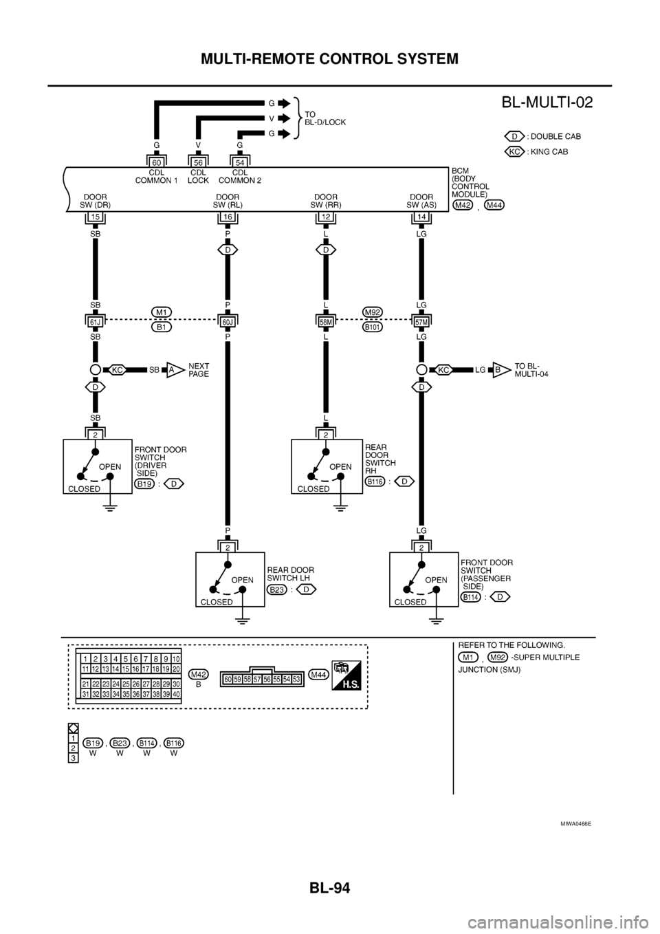
When the front door switch (driver side) is ON (door is OPEN), ground is supplied
lto BCM terminal 15
lthrough front door switch (driver side) terminal 2
lto front door switch (driver side) case ground.
When the front door switch (passenger side) is ON (door is OPEN), ground is supplied
lto BCM terminal 14
lthrough front door switch (passenger side) terminal 2
lto front door switch (passenger side) case ground.
When the rear door switch LH is ON (door is OPEN), ground is supplied
lto BCM terminal 16
lthrough rear door switch LH terminal 2
lto rear door switch LH case ground.
When the rear door switch RH is ON (door is OPEN), ground is supplied
lto BCM terminal 12
lthrough rear door switch RH terminal 2
lto rear door switch RH case ground.
The multi-remote control system controls operation of the
lpowerdoorlock
linterior lamp and ignition keyhole illumination
lhazard reminder
lauto door lock operation
OPERATING PROCEDURE
Power Door Lock Operation
BCM receives a LOCK signal from keyfob. BCM locks all doors with input of LOCK signal from keyfob.
When an UNLOCK signal is sent from keyfob once, driver's door is unlocked.
Then, if an UNLOCK signal is sent from keyfob again within 5 seconds, all doors are unlocked.
Hazard Reminder
When the doors are locked or unlocked by keyfob, power is supplied to hazard warning lamp.
Hazard reminder does not operate if any door switches are ON (any doors are OPEN).
How to change hazard and horn reminder mode
Hazard and horn reminder can be changed using “WORK SUPPORT” mode in “MULTI ANSWER BACK SET”.
Refer toBL-102, "
CONSULT-II Function (BCM)".
Page 676 of 3171
BL-92
MULTI-REMOTE CONTROL SYSTEM
Auto Re-lock Function
The BCM is equipped with an auto re-lock function, when no further user action occurs after an full or partial
unlock, the doors will automatically re-lock after 2 minutes (default value).
The auto re-lock function will not be activated under the following state.
lKeyswitchisOn
lMechanical key is inserted
lAny door is opened
NOTE:
The 2 minutes timer of auto re-lock will be reset if unlock button from the key fob is pressed.
Auto relock function can be changed using “WORK SUPPORT” mode in “AUTO LOCK SET”.
Refer toBL-104, "
Work Support".
Room Lamp Operation
When the following conditions are met:
lcondition of room lamp switch is DOOR position;
ldoor switch OFF (when all the doors are closed);
With input of UNLOCK signal from keyfob multi-remote control system turns on interior lamp (for 30 seconds).
CAN Communication System DescriptionEIS00DBF
Refer toLAN-23, "CAN COMMUNICATION".
Page 677 of 3171
MULTI-REMOTE CONTROL SYSTEM
BL-93
C
D
E
F
G
H
J
K
L
MA
B
BL
WiringDiagram—MULTI—ForLHDModelsEIS00DBG
MIWA0214E
Page 678 of 3171
BL-94
MULTI-REMOTE CONTROL SYSTEM
MIWA0466E
Page 679 of 3171
MULTI-REMOTE CONTROL SYSTEM
BL-95
C
D
E
F
G
H
J
K
L
MA
B
BL
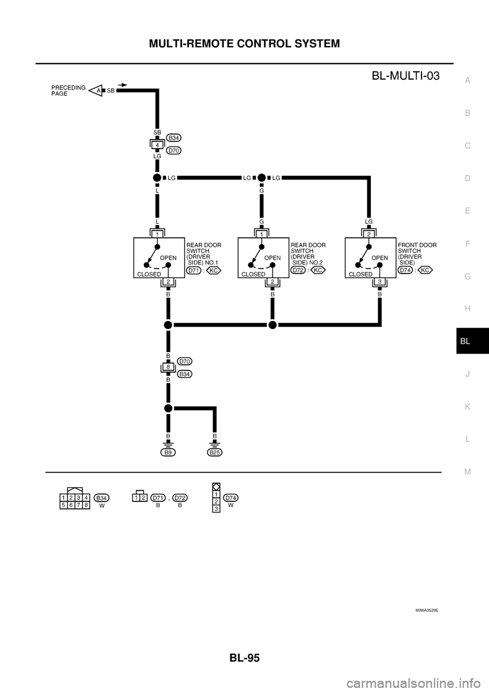
MIWA0529E
Page 680 of 3171
BL-96
MULTI-REMOTE CONTROL SYSTEM
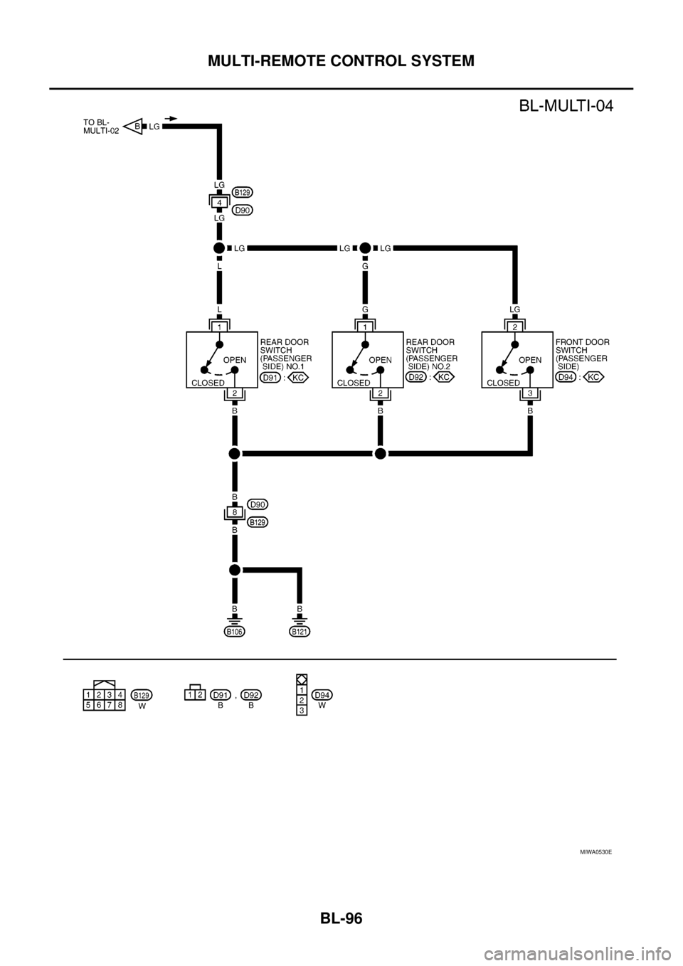
MIWA0530E
Trending: wheel bolts, fuse chart, height adjustment, maintenance reset, ignition, engine coolant, Em 49
