roof NISSAN NAVARA 2005 Repair Workshop Manual
[x] Cancel search | Manufacturer: NISSAN, Model Year: 2005, Model line: NAVARA, Model: NISSAN NAVARA 2005Pages: 3171, PDF Size: 49.59 MB
Page 1 of 3171
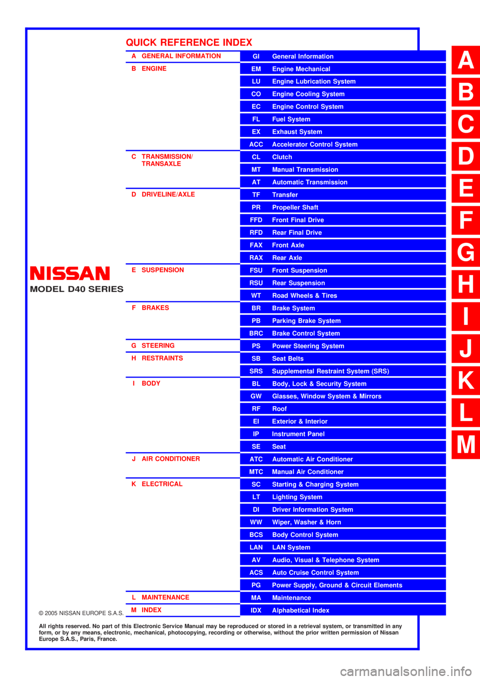
MODELD40 SERIES
2005 NISSAN EUROPE S.A.S.
All rights reserved. No part of this Electronic Service Manual may be reproduced or stored in a retrieval system, or transmitted in any
form, or by any means, electronic, mechanical, photocopying, recording or otherwise, without the prior written permission of Nissan
Europe S.A.S., Paris, France.
A GENERAL INFORMATION
B ENGINE
C TRANSMISSION/TRANSAXLE
D DRIVELINE/AXLE
E SUSPENSION F BRAKES
G STEERING H RESTRAINTS
I BODY
J AIR CONDITIONER
K ELECTRICAL
L MAINTENANCE
M INDEXGI General Information
EM Engine Mechanical
LU Engine Lubrication System
CO Engine Cooling System
EC Engine Control System
FL Fuel System
EX Exhaust System
ACC Accelerator Control System
CL Clutch
MTManualTransmission
AT Automatic Transmission
TF Transfer
PR Propeller Shaft
FFD Front Final Drive
RFD Rear Final Drive
FAX Front Axle
RAX Rear Axle
FSU Front Suspension
RSU Rear Suspension
WT Road Wheels & Tires
BR Brake System
PB Parking Brake System
BRC Brake Control System
PS Power Steering System
SB Seat Belts
SRS Supplemental Restraint System (SRS)
BL Body, Lock & Security System
GW Glasses, Window System & Mirrors
RF Roof
EI Exterior & Interior
IP Instrument Panel
SE Seat
ATC Automatic Air Conditioner
MTC Manual Air Conditioner
SC Starting & Charging System
LT Lighting System
DI Driver Information System
WW Wiper, Washer & Horn
BCS Body Control System
LAN LAN System
AV Audio, Visual & Telephone System
ACS Auto Cruise Control System
PG Power Supply, Ground & Circuit Elements
MA Maintenance
IDX Alphabetical Index
QUICK REFERENCE INDEX
A
B
C
D
E
F
G
H
I
J
K
L
M
Page 490 of 3171

AV-2
TION .................................................................... 63
Example of Symptoms Not Malfunction .................. 65
BASIC OPERATION ............................................ 65
VEHICLE ICON ................................................... 65
MAP DVD-ROM ................................................... 66
ROUTE CALCULATION AND VISUAL GUID-
ANCE ................................................................... 66
VOICE GUIDANCE ............................................. 67
VOICE RECOGNITION ....................................... 67
EXAMPLES OF CURRENT LOCATION MARK
DISPLACEMENT ................................................. 68
THE CURRENT POSITION MARK SHOWS A
POSITION THAT IS COMPLETELY INCOR-
RECT. .................................................................. 71
THE CURRENT POSITION MARK JUMPS. ....... 72
THE CURRENT LOCATION MARK IS IN A
RIVER OR THE SEA. .......................................... 72
CURRENT LOCATION MARK ROTATES WITH-
OUT OPERATION ............................................... 72
WHEN DRIVING ON THE SAME ROAD, SOME-
TIMES THE CURRENT LOCATION MARK IS IN
THE CORRECT PLACE AND SOMETIMES IT IS
IN THE INCORRECT PLACE. ............................. 72
LOCATION CORRECTION BY MAP MATCHING
IS SLOW. ............................................................. 72
ALTHOUGH THE GPS RECEIVING DISPLAY IS
GREEN, THE VEHICLE MARK DOES NOT
RETURN TO THE CORRECT LOCATION. ......... 72
THE NAME OF THE CURRENT PLACE IS NOT
DISPLAYED. ........................................................ 72
THE DISPLAY IS DIFFERENT BETWEEN BIRD-
VIEW® AND (FLAT) MAP DISPLAY. ................... 72
REMOVAL AND INSTALLATION ............................. 73
Auido Unit (1CD Player Type) ................................ 73
REMOVAL ........................................................... 73INSTALLATION .................................................... 73
Audio Unit ( 6CD Player Type ) Without NAVI ........ 73
REMOVAL ............................................................ 73
INSTALLATION .................................................... 73
Audio Unit (6CD Player Type) With NAVI ............... 74
REMOVAL ............................................................ 74
INSTALLATION .................................................... 74
Front Door Speaker ................................................ 74
REMOVAL ............................................................ 74
INSTALLATION .................................................... 74
Rear Door Speaker ................................................. 74
REMOVAL ............................................................ 74
INSTALLATION .................................................... 74
Tweeter ................................................................... 75
REMOVAL ............................................................ 75
INSTALLATION .................................................... 75
Roof Antenna .......................................................... 75
REMOVAL ............................................................ 75
INSTALLATION .................................................... 75
NAVI Control Unit .................................................... 75
REMOVAL ............................................................ 75
INSTALLATION .................................................... 75
GPS Antenna .......................................................... 76
REMOVAL ............................................................ 76
INSTALLATION .................................................... 76
Display Unit ............................................................. 77
REMOVAL ............................................................ 77
INSTALLATION .................................................... 77
AV Switch ................................................................ 77
REMOVAL ............................................................ 77
INSTALLATION .................................................... 77
Microphone ............................................................. 77
REMOVAL ............................................................ 77
INSTALLATION .................................................... 77
Page 498 of 3171
AV-10
SYSTEM DESCRIPTION
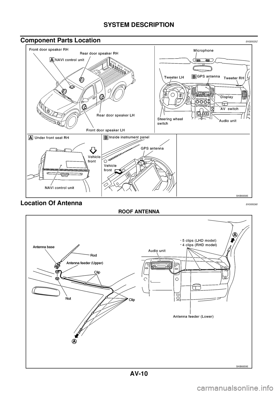
Component Parts Location
EKS00Q5Z
Location Of AntennaEKS00Q60
ROOF ANTENNA
SKIB6658E
SKIB6659E
Page 563 of 3171
REMOVAL AND INSTALLATION
AV-75
C
D
E
F
G
H
I
J
L
MA
B
AV
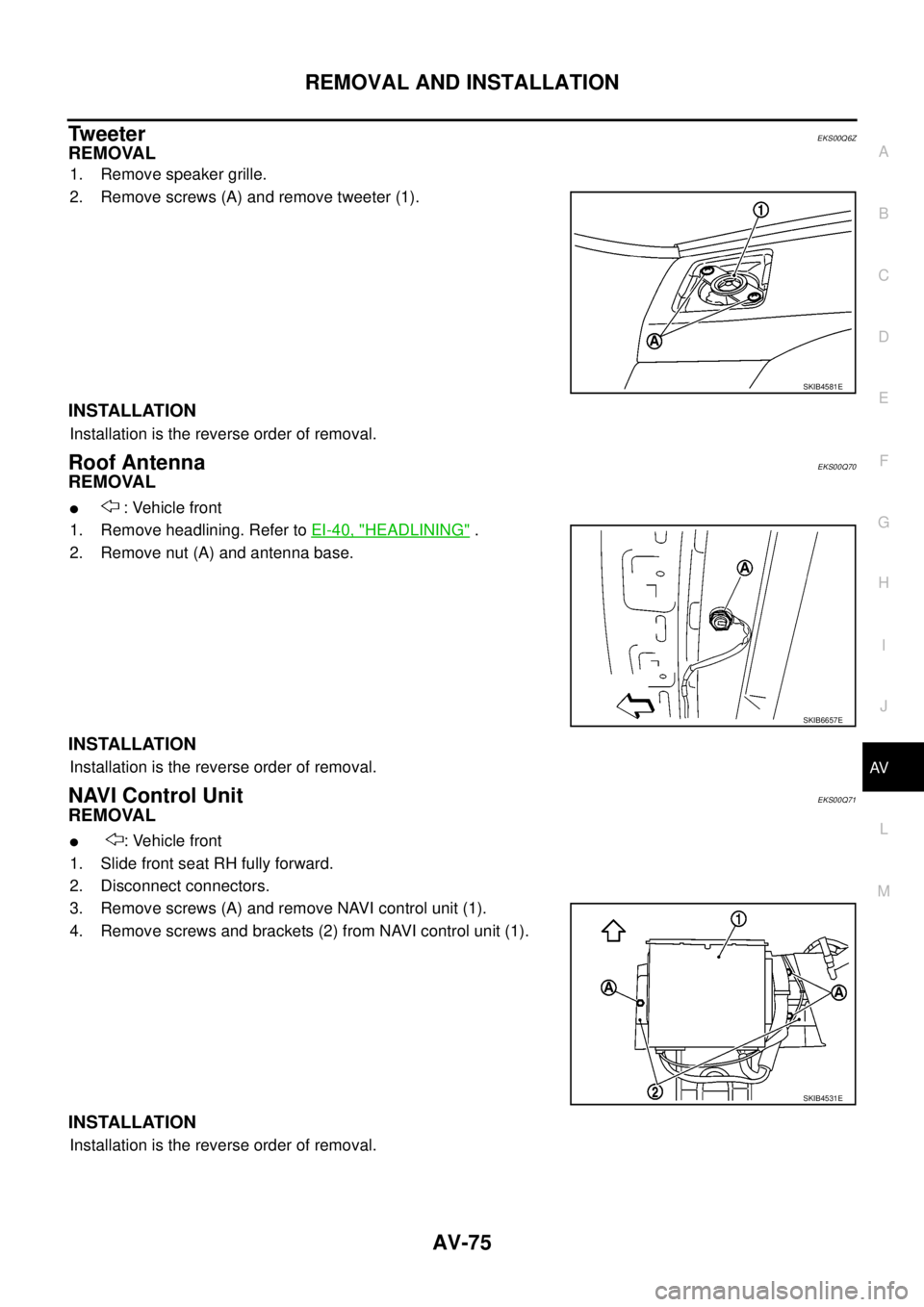
Tw e e t e rEKS00Q6Z
REMOVAL
1. Remove speaker grille.
2. Remove screws (A) and remove tweeter (1).
INSTALLATION
Installation is the reverse order of removal.
Roof AntennaEKS00Q70
REMOVAL
l: Vehicle front
1. Remove headlining. Refer toEI-40, "
HEADLINING".
2. Remove nut (A) and antenna base.
INSTALLATION
Installation is the reverse order of removal.
NAVI Control UnitEKS00Q71
REMOVAL
l: Vehicle front
1. Slide front seat RH fully forward.
2. Disconnect connectors.
3. Remove screws (A) and remove NAVI control unit (1).
4. Remove screws and brackets (2) from NAVI control unit (1).
INSTALLATION
Installation is the reverse order of removal.
SKIB4581E
SKIB6657E
SKIB4531E
Page 565 of 3171
REMOVAL AND INSTALLATION
AV-77
C
D
E
F
G
H
I
J
L
MA
B
AV
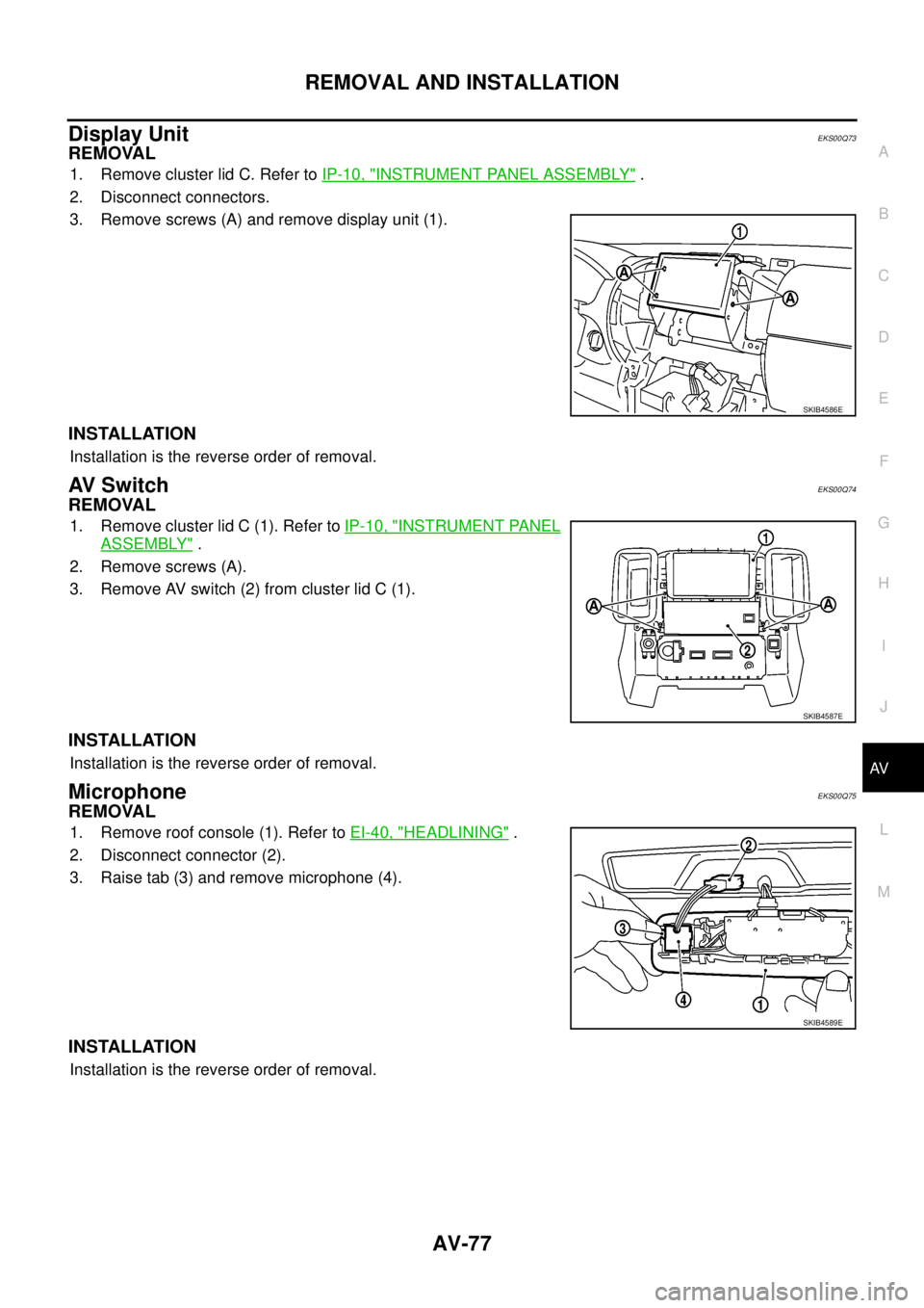
Display UnitEKS00Q73
REMOVAL
1. Remove cluster lid C. Refer toIP-10, "INSTRUMENT PANEL ASSEMBLY".
2. Disconnect connectors.
3. Remove screws (A) and remove display unit (1).
INSTALLATION
Installation is the reverse order of removal.
AV S w i t c hEKS00Q74
REMOVAL
1. Remove cluster lid C (1). Refer toIP-10, "INSTRUMENT PANEL
ASSEMBLY".
2. Remove screws (A).
3. Remove AV switch (2) from cluster lid C (1).
INSTALLATION
Installation is the reverse order of removal.
MicrophoneEKS00Q75
REMOVAL
1. Remove roof console (1). Refer toEI-40, "HEADLINING".
2. Disconnect connector (2).
3. Raise tab (3) and remove microphone (4).
INSTALLATION
Installation is the reverse order of removal.
SKIB4586E
SKIB4587E
SKIB4589E
Page 574 of 3171
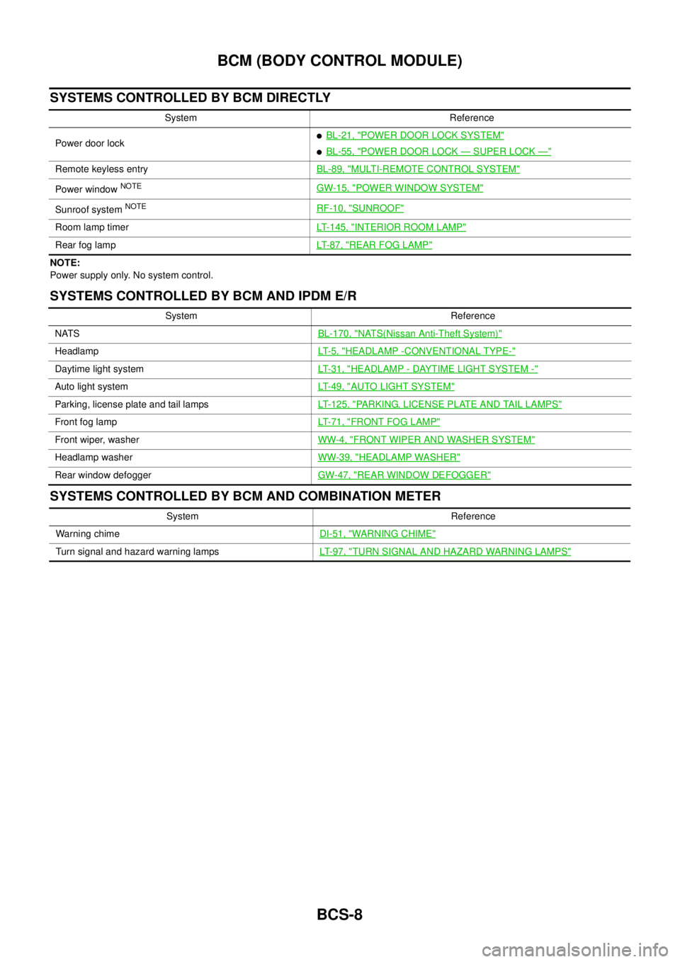
BCS-8
BCM (BODY CONTROL MODULE)
SYSTEMS CONTROLLED BY BCM DIRECTLY
NOTE:
Power supply only. No system control.
SYSTEMS CONTROLLED BY BCM AND IPDM E/R
SYSTEMS CONTROLLED BY BCM AND COMBINATION METER
System Reference
Power door lock
lBL-21, "POWER DOOR LOCK SYSTEM"
lBL-55, "POWER DOOR LOCK—SUPER LOCK—"
Remote keyless entryBL-89, "MULTI-REMOTE CONTROL SYSTEM"
Power windowNOTEGW-15, "POWER WINDOW SYSTEM"
Sunroof systemNOTERF-10, "SUNROOF"
Room lamp timerLT-145, "INTERIOR ROOM LAMP"
Rear fog lampLT- 8 7 , "REAR FOG LAMP"
System Reference
NATSBL-170, "
NATS(Nissan Anti-Theft System)"
HeadlampLT- 5 , "HEADLAMP -CONVENTIONAL TYPE-"
Daytime light systemLT-31, "HEADLAMP - DAYTIME LIGHT SYSTEM -"
Auto light systemLT-49, "AUTO LIGHT SYSTEM"
Parking, license plate and tail lampsLT-125, "PARKING, LICENSE PLATE AND TAIL LAMPS"
Front fog lampLT-71, "FRONT FOG LAMP"
Front wiper, washerWW-4, "FRONT WIPER AND WASHER SYSTEM"
Headlamp washerWW-39, "HEADLAMP WASHER"
Rear window defoggerGW-47, "REAR WINDOW DEFOGGER"
System Reference
Warning chimeDI-51, "
WARNING CHIME"
Turn signal and hazard warning lampsLT-97, "TURN SIGNAL AND HAZARD WARNING LAMPS"
Page 575 of 3171
BCM (BODY CONTROL MODULE)
BCS-9
C
D
E
F
G
H
I
J
L
MA
B
BCS
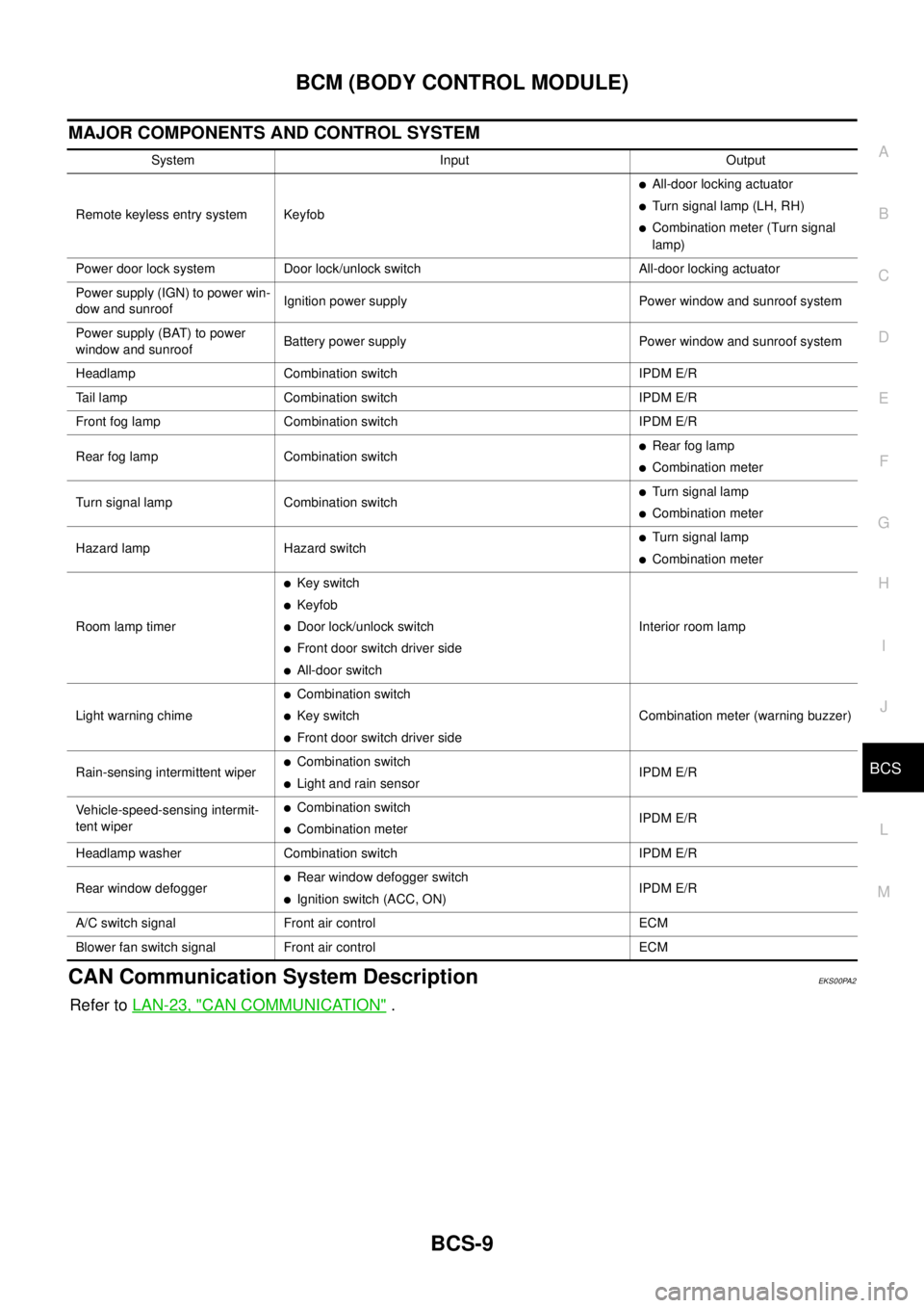
MAJOR COMPONENTS AND CONTROL SYSTEM
CAN Communication System DescriptionEKS00PA2
Refer toLAN-23, "CAN COMMUNICATION".
System Input Output
Remote keyless entry system Keyfob
lAll-door locking actuator
lTurn signal lamp (LH, RH)
lCombination meter (Turn signal
lamp)
Power door lock system Door lock/unlock switch All-door locking actuator
Power supply (IGN) to power win-
dow and sunroofIgnition power supply Power window and sunroof system
Power supply (BAT) to power
window and sunroofBattery power supply Power window and sunroof system
Headlamp Combination switch IPDM E/R
Tail lamp Combination switch IPDM E/R
Front fog lamp Combination switch IPDM E/R
Rear fog lamp Combination switch
lRear fog lamp
lCombination meter
Turn signal lamp Combination switch
lTurn signal lamp
lCombination meter
Hazard lamp Hazard switch
lTurn signal lamp
lCombination meter
Room lamp timer
lKey switch
lKeyfob
lDoor lock/unlock switch
lFront door switch driver side
lAll-door switchInterior room lamp
Light warning chime
lCombination switch
lKey switch
lFront door switch driver sideCombination meter (warning buzzer)
Rain-sensing intermittent wiper
lCombination switch
lLight and rain sensorIPDM E/R
Vehicle-speed-sensing intermit-
tent wiper
lCombination switch
lCombination meterIPDM E/R
Headlamp washer Combination switch IPDM E/R
Rear window defogger
lRear window defogger switch
lIgnition switch (ACC, ON)IPDM E/R
A/C switch signal Front air control ECM
Blower fan switch signal Front air control ECM
Page 585 of 3171
BL-1
BODY, LOCK & SECURITY SYSTEM
IBODY
CONTENTS
C
D
E
F
G
H
J
K
L
M
SECTIONBL
A
B
BL
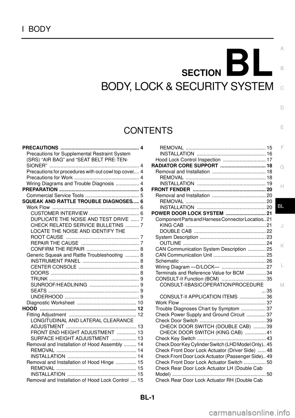
BODY, LOCK & SECURITY SYSTEM
PRECAUTIONS .......................................................... 4
Precautions for Supplemental Restraint System
(SRS)“AIRBAG”and“SEATBELTPRE-TEN-
SIONER” .................................................................. 4
Precautions for procedures with out cowl top cover..... 4
Precautions for Work ................................................ 4
Wiring Diagrams and Trouble Diagnosis .................. 4
PREPARATION ........................................................... 5
Commercial Service Tools ........................................ 5
SQUEAK AND RATTLE TROUBLE DIAGNOSES..... 6
Work Flow ................................................................ 6
CUSTOMER INTERVIEW ..................................... 6
DUPLICATE THE NOISE AND TEST DRIVE ....... 7
CHECK RELATED SERVICE BULLETINS ........... 7
LOCATE THE NOISE AND IDENTIFY THE
ROOT CAUSE ...................................................... 7
REPAIR THE CAUSE ........................................... 7
CONFIRM THE REPAIR ....................................... 8
Generic Squeak and Rattle Troubleshooting ........... 8
INSTRUMENT PANEL .......................................... 8
CENTER CONSOLE ............................................. 8
DOORS ................................................................. 8
TRUNK .................................................................. 9
SUNROOF/HEADLINING ..................................... 9
SEATS ................................................................... 9
UNDERHOOD ....................................................... 9
Diagnostic Worksheet ............................................ 10
HOOD ....................................................................... 12
Fitting Adjustment .................................................. 12
LONGITUDINAL AND LATERAL CLEARANCE
ADJUSTMENT .................................................... 13
FRONT END HEIGHT ADJUSTMENT ............... 13
SURFACE HEIGHT ADJUSTMENT ................... 13
Removal and Installation of Hood Assembly .......... 14
REMOVAL ........................................................... 14
INSTALLATION ................................................... 14
Removal and Installation of Hood Hinge ................ 15
REMOVAL ........................................................... 15
INSTALLATION ................................................... 15
Removal and Installation of Hood Lock Control ..... 15REMOVAL ........................................................... 15
INSTALLATION ................................................... 16
Hood Lock Control Inspection ................................ 17
RADIATOR CORE SUPPORT .................................. 18
Removal and Installation ........................................ 18
REMOVAL ........................................................... 18
INSTALLATION ................................................... 19
FRONT FENDER ...................................................... 20
Removal and Installation ........................................ 20
REMOVAL ........................................................... 20
INSTALLATION ................................................... 20
POWER DOOR LOCK SYSTEM .............................. 21
Component Parts and Harness Connector Location... 21
KING CAB ........................................................... 21
DOUBLE CAB ..................................................... 22
System Description ................................................. 23
OUTLINE ............................................................. 24
CAN Communication System Description .............. 25
CAN Communication Unit ....................................... 25
Schematic ............................................................... 26
Wiring Diagram —D/LOCK— ................................. 27
Terminals and Reference Value for BCM ............... 34
CONSULT-II Function (BCM) ................................. 35
CONSULT-II BASIC OPERATION PROCEDURE
... 35
CONSULT-II APPLICATION ITEMS .................... 36
Work Flow ............................................................... 37
Trouble Diagnoses Chart by Symptom ................... 37
Check Power Supply and Ground Circuit ............... 37
Check Door Switch ................................................. 39
CHECK DOOR SWITCH (DOUBLE CAB) .......... 39
CHECK DOOR SWITCH (KING CAB) ................ 41
Check Key Switch ................................................... 43
Check Door Key Cylinder Switch (LHD Model Only)... 45
Check Front Door Lock Actuator (Driver Side) ....... 48
Check Front Door Lock Actuator (Passenger Side)... 49
Check Front Door Lock Actuator Switch ................. 50
Check Rear Door Lock Actuator LH (Double Cab
Model) ..................................................................... 50
Check Rear Door Lock Actuator RH (Double Cab
Page 593 of 3171
SQUEAK AND RATTLE TROUBLE DIAGNOSES
BL-9
C
D
E
F
G
H
J
K
L
MA
B
BL
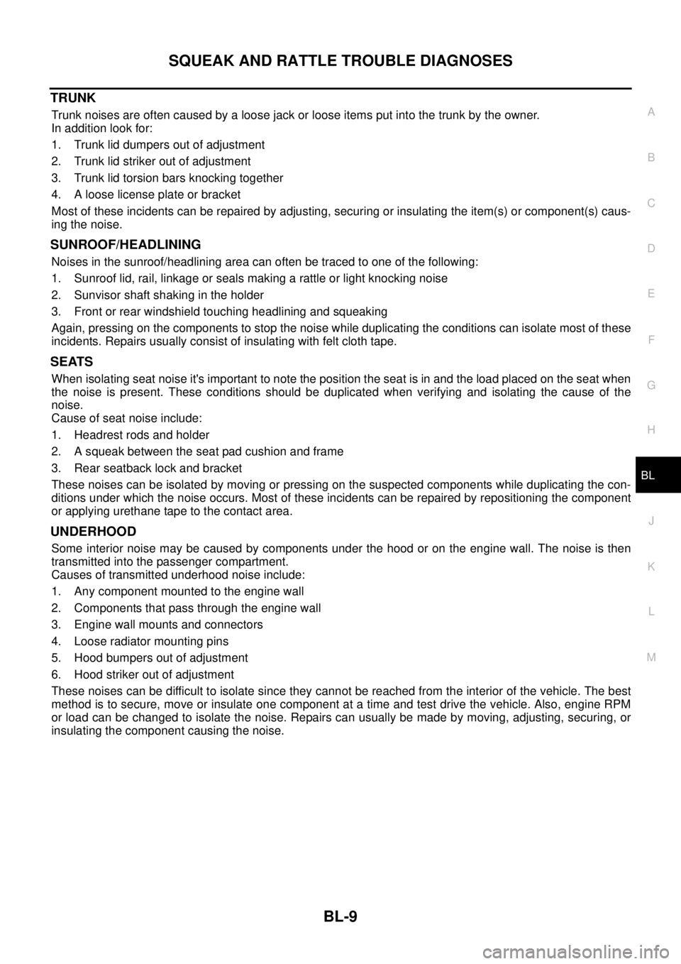
TRUNK
Trunk noises are often caused by a loose jack or loose items put into the trunk by the owner.
In addition look for:
1. Trunk lid dumpers out of adjustment
2. Trunk lid striker out of adjustment
3. Trunk lid torsion bars knocking together
4. A loose license plate or bracket
Most of these incidents can be repaired by adjusting, securing or insulating the item(s) or component(s) caus-
ing the noise.
SUNROOF/HEADLINING
Noises in the sunroof/headlining area can often be traced to one of the following:
1. Sunroof lid, rail, linkage or seals making a rattle or light knocking noise
2. Sunvisor shaft shaking in the holder
3. Front or rear windshield touching headlining and squeaking
Again, pressing on the components to stop the noise while duplicating the conditions can isolate most of these
incidents. Repairs usually consist of insulating with felt cloth tape.
SEATS
When isolating seat noise it's important to note the position the seat is in and the load placed on the seat when
the noise is present. These conditions should be duplicated when verifying and isolating the cause of the
noise.
Cause of seat noise include:
1. Headrest rods and holder
2. A squeak between the seat pad cushion and frame
3. Rear seatback lock and bracket
These noises can be isolated by moving or pressing on the suspected components while duplicating the con-
ditions under which the noise occurs. Most of these incidents can be repaired by repositioning the component
or applying urethane tape to the contact area.
UNDERHOOD
Some interior noise may be caused by components under the hood or on the engine wall. The noise is then
transmitted into the passenger compartment.
Causes of transmitted underhood noise include:
1. Any component mounted to the engine wall
2. Components that pass through the engine wall
3. Engine wall mounts and connectors
4. Loose radiator mounting pins
5. Hood bumpers out of adjustment
6. Hood striker out of adjustment
These noises can be difficult to isolate since they cannot be reached from the interior of the vehicle. The best
method is to secure, move or insulate one component at a time and test drive the vehicle. Also, engine RPM
or load can be changed to isolate the noise. Repairs can usually be made by moving, adjusting, securing, or
insulating the component causing the noise.
Page 1339 of 3171
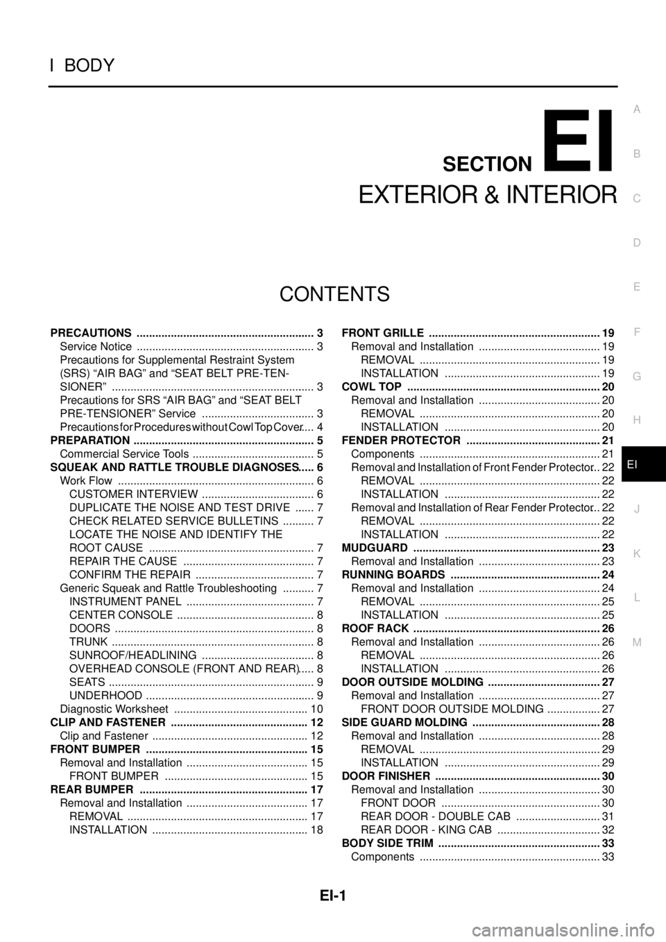
EI-1
EXTERIOR & INTERIOR
IBODY
CONTENTS
C
D
E
F
G
H
J
K
L
M
SECTIONEI
A
B
EI
EXTERIOR & INTERIOR
PRECAUTIONS .......................................................... 3
Service Notice .......................................................... 3
Precautions for Supplemental Restraint System
(SRS)“AIRBAG”and“SEATBELTPRE-TEN-
SIONER” .................................................................. 3
Precautions for SRS “AIR BAG” and “SEAT BELT
PRE-TENSIONER” Service ..................................... 3
Precautions for Procedures without Cowl Top Cover..... 4
PREPARATION ........................................................... 5
Commercial Service Tools ........................................ 5
SQUEAK AND RATTLE TROUBLE DIAGNOSES..... 6
Work Flow ................................................................ 6
CUSTOMER INTERVIEW ..................................... 6
DUPLICATE THE NOISE AND TEST DRIVE ....... 7
CHECK RELATED SERVICE BULLETINS ........... 7
LOCATE THE NOISE AND IDENTIFY THE
ROOT CAUSE ...................................................... 7
REPAIR THE CAUSE ........................................... 7
CONFIRM THE REPAIR ....................................... 7
Generic Squeak and Rattle Troubleshooting ........... 7
INSTRUMENT PANEL .......................................... 7
CENTER CONSOLE ............................................. 8
DOORS ................................................................. 8
TRUNK .................................................................. 8
SUNROOF/HEADLINING ..................................... 8
OVERHEAD CONSOLE (FRONT AND REAR)..... 8
SEATS ................................................................... 9
UNDERHOOD ....................................................... 9
Diagnostic Worksheet ............................................ 10
CLIP AND FASTENER ............................................. 12
Clip and Fastener ................................................... 12
FRONT BUMPER ..................................................... 15
Removal and Installation ........................................ 15
FRONT BUMPER ............................................... 15
REAR BUMPER ....................................................... 17
Removal and Installation ........................................ 17
REMOVAL ........................................................... 17
INSTALLATION ................................................... 18FRONT GRILLE ........................................................ 19
Removal and Installation ........................................ 19
REMOVAL ........................................................... 19
INSTALLATION ................................................... 19
COWL TOP ............................................................... 20
Removal and Installation ........................................ 20
REMOVAL ........................................................... 20
INSTALLATION ................................................... 20
FENDER PROTECTOR ............................................ 21
Components ........................................................... 21
Removal and Installation of Front Fender Protector... 22
REMOVAL ........................................................... 22
INSTALLATION ................................................... 22
Removal and Installation of Rear Fender Protector... 22
REMOVAL ........................................................... 22
INSTALLATION ................................................... 22
MUDGUARD ............................................................. 23
Removal and Installation ........................................ 23
RUNNING BOARDS ................................................. 24
Removal and Installation ........................................ 24
REMOVAL ........................................................... 25
INSTALLATION ................................................... 25
ROOF RACK ............................................................. 26
Removal and Installation ........................................ 26
REMOVAL ........................................................... 26
INSTALLATION ................................................... 26
DOOR OUTSIDE MOLDING ..................................... 27
Removal and Installation ........................................ 27
FRONT DOOR OUTSIDE MOLDING .................. 27
SIDE GUARD MOLDING .......................................... 28
Removal and Installation ........................................ 28
REMOVAL ........................................................... 29
INSTALLATION ................................................... 29
DOOR FINISHER ...................................................... 30
Removal and Installation ........................................ 30
FRONT DOOR .................................................... 30
REAR DOOR - DOUBLE CAB ............................ 31
REAR DOOR - KING CAB .................................. 32
BODY SIDE TRIM ..................................................... 33
Components ........................................................... 33