NISSAN NOTE 2016 Service Repair Manual
Manufacturer: NISSAN, Model Year: 2016, Model line: NOTE, Model: NISSAN NOTE 2016Pages: 3641, PDF Size: 28.72 MB
Page 2091 of 3641
FRONT AIR CONTROL FINISHERIP-23
< REMOVAL AND INSTALLATION >
C
DE
F
G H
I
K L
M A
B
IP
N
O P
FRONT AIR CONTROL FINISHER
Removal and InstallationINFOID:0000000012430785
REMOVAL
1. Remove cluster lid C. Refer to IP-22, "Removal and Installation".
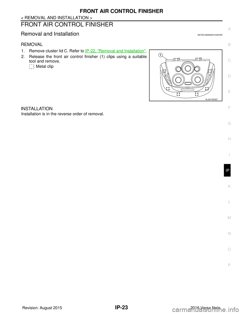
2. Release the front air control finisher (1) clips using a suitable tool and remove.
: Metal clip
INSTALLATION
Installation is in the reverse order of removal.
ALJIA1500ZZ
Revision: August 2015 2016 Versa Note
cardiagn.com
Page 2092 of 3641
IP-24
< REMOVAL AND INSTALLATION >
INSTRUMENT LOWER PANEL LH
INSTRUMENT LOWER PANEL LH
Removal and InstallationINFOID:0000000012430786
REMOVAL
1. Remove data link connector from instrument lower panel LH.
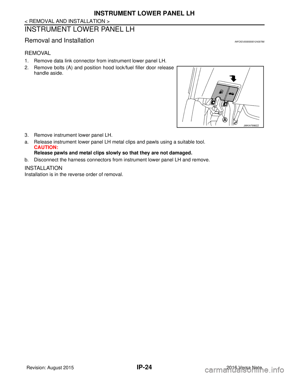
2. Remove bolts (A) and position hood lock/fuel filler door releasehandle aside.
3. Remove instrument lower panel LH.
a. Release instrument lower panel LH metal clips and pawls using a suitable tool. CAUTION:
Release pawls and metal clips slowly so that they are not damaged.
b. Disconnect the harness connectors from instrument lower panel LH and remove.
INSTALLATION
Installation is in the reverse order of removal.
JMKIA7998ZZ
Revision: August 2015 2016 Versa Note
cardiagn.com
Page 2093 of 3641
GLOVE BOX ASSEMBLYIP-25
< REMOVAL AND INSTALLATION >
C
DE
F
G H
I
K L
M A
B
IP
N
O P
GLOVE BOX ASSEMBLY
Removal and InstallationINFOID:0000000012430787
REMOVAL
1. Remove glove box lid.
a. Open glove box lid.
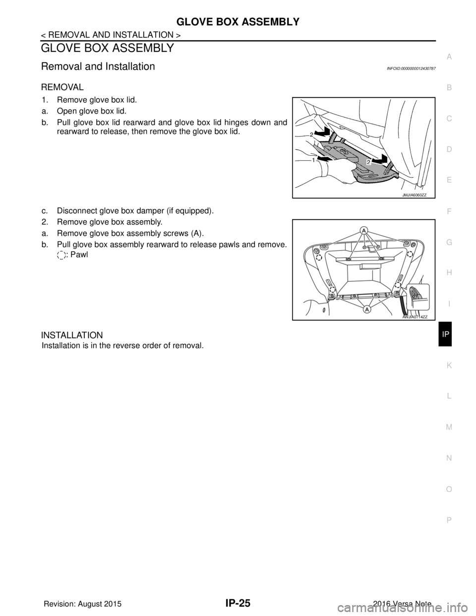
b. Pull glove box lid rearward and glove box lid hinges down and rearward to release, then remove the glove box lid.
c. Disconnect glove box damper (if equipped).
2. Remove glove box assembly.
a. Remove glove box assembly screws (A).
b. Pull glove box assembly rearward to release pawls and remove. : Pawl
INSTALLATION
Installation is in the reverse order of removal.
JMJIA6060ZZ
AWJIA0714ZZ
Revision: August 2015 2016 Versa Note
cardiagn.com
Page 2094 of 3641
IP-26
< REMOVAL AND INSTALLATION >
UPPER GLOVE BOX
UPPER GLOVE BOX
Removal and InstallationINFOID:0000000012430788
REMOVAL
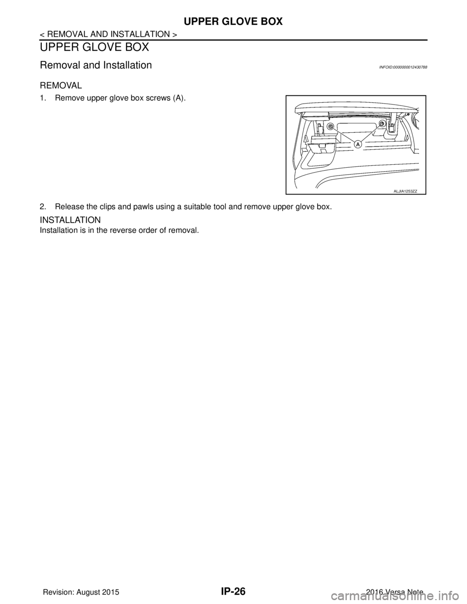
1. Remove upper glove box screws (A).
2. Release the clips and pawls using a suitable tool and remove upper glove box.
INSTALLATION
Installation is in the reverse order of removal.
ALJIA1253ZZ
Revision: August 20152016 Versa Note
cardiagn.com
Page 2095 of 3641

INL-1
DRIVER CONTROLS
C
DE
F
G H
I
J
K
M
SECTION INL
A
B
INL
N
O P
CONTENTS
INTERIOR LIGHTING SYSTEM
PRECAUTION ....... ........................................3
PRECAUTIONS .............................................. .....3
Precaution for Supplemental Restraint System
(SRS) "AIR BAG" and "SEAT BELT PRE-TEN-
SIONER" ............................................................. ......
3
Precaution for Work ..................................................3
PREPARATION ............................................4
PREPARATION .............................................. .....4
Special Service Tool ........................................... ......4
SYSTEM DESCRIPTION ..............................5
COMPONENT PARTS ................................... .....5
Component Parts Location .................................. ......5
SYSTEM ..............................................................7
INTERIOR ROOM LAMP CONTROL SYSTEM .... ......7
INTERIOR ROOM LAMP CONTROL SYSTEM :
System Description ...................................................
7
ILLUMINATION CONTROL SYSTEM ................... ......9
ILLUMINATION CONTROL SYSTEM : System
Description ................................................................
9
DIAGNOSIS SYSTEM (BCM) (WITH INTELLI-
GENT KEY SYSTEM) .........................................
10
COMMON ITEM ..................................................... ....10
COMMON ITEM : CONSULT Function (BCM -
COMMON ITEM) .....................................................
10
DOOR LOCK ......................................................... ....11
DOOR LOCK : CONSULT Function (BCM -
DOOR LOCK) .........................................................
11
INT LAMP .............................................................. ....11
INT LAMP : CONSULT Function (BCM - INT
LAMP) .....................................................................
11
INTELLIGENT KEY ............................................... ....12
INTELLIGENT KEY : CONSULT Function (BCM -
INTELLIGENT KEY) ................................................
12
BATTERY SAVER ................................................. ....14
BATTERY SAVER : CONSULT Function (BCM -
BATTERY SAVER) ..................................................
14
DIAGNOSIS SYSTEM (BCM) (WITHOUT IN-
TELLIGENT KEY SYSTEM) .............................
16
COMMON ITEM ..................................................... ....16
COMMON ITEM : CONSULT Function (BCM -
COMMON ITEM) .....................................................
16
DOOR LOCK .......................................................... ....17
DOOR LOCK : CONSULT Function (BCM -
DOOR LOCK) ..........................................................
17
INT LAMP ............................................................... ....17
INT LAMP : CONSULT Function (BCM - INT
LAMP) ......................................................................
18
BATTERY SAVER ................................................. ....19
BATTERY SAVER : CONSULT Function (BCM -
BATTERY SAVER) ..................................................
19
ECU DIAGNOSIS INFO RMATION ..............20
BCM ...................................................................20
List of ECU Reference ......................................... ....20
WIRING DIAGRAM ......................................21
INTERIOR ROOM LAMP CONTROL SYSTEM
...
21
Wiring Diagram .................................................... ....21
ILLUMINATION .................................................28
Wiring Diagram ........................................................28
BASIC INSPECTION ...................................37
DIAGNOSIS AND REPAIR WORKFLOW ........37
Work Flow ............................................................ ....37
Revision: August 2015 2016 Versa Note
cardiagn.com
Page 2096 of 3641

INL-2
DTC/CIRCUIT DIAGNOSIS ...................... ...39
POWER SUPPLY AND GROUND CIRCUIT .. ...39
BCM (BODY CONTROL SYSTEM) (WITH INTEL-
LIGENT KEY SYSTEM) ..... .......................................
39
BCM (BODY CONTROL S YSTEM) (WITH INTEL-
LIGENT KEY SYSTEM) : Dia gnosis Procedure .....
39
BCM (BODY CONTROL SYST EM) (WITHOUT IN-
TELLIGENT KEY SYSTEM) . ....................................
39
BCM (BODY CONTROL SYSTEM) (WITHOUT
INTELLIGENT KEY SYSTEM) : Diagnosis Proce-
dure ..................................................................... ...
39
BATTERY SAVER OUTPUT/POWER SUP-
PLY CIRCUIT .....................................................
41
Description ........................................................... ...41
Component Function Check ...................................41
Diagnosis Procedure ..............................................41
INTERIOR ROOM LAMP CONTROL CIRCUIT
...
43
Description ........................................................... ...43
Component Function Check ...................................43
Diagnosis Procedure ..............................................43
CARGO LAMP CONTROL CIRCUIT ................46
Description ........................................................... ...46
Component Function Check ...................................46
Diagnosis Procedure ..............................................46
PUSH-BUTTON IGNITION SWITCH ILLUMI-
NATION CIRCUIT ..............................................
48
Description ........................................................... ...48
Component Function Check ...................................48
Diagnosis Procedure ............................................ ...48
SYMPTOM DIAGNOSIS ............................50
INTERIOR LIGHTING SYSTEM SYMPTOMS ...50
Symptom Table .................................................... ...50
REMOVAL AND INSTALLATION ..............51
MAP LAMP ........................................................51
Exploded View ..................................................... ...51
Removal and Installation .........................................51
Bulb Replacement ................................................ ...51
INTERIOR ROOM LAMP ...................................53
Exploded View ..................................................... ...53
Removal and Installation .........................................53
Bulb Replacement ................................................ ...53
CARGO ROOM LAMP ......................................54
Exploded View ..................................................... ...54
Removal and Installation .........................................54
Bulb Replacement ................................................ ...54
SHIFT SELECTOR LAMP .................................55
Bulb Replacement ...................................................55
ILLUMINATION CONTROL SWITCH ...............56
Removal and Installation .........................................56
SERVICE DATA AND SPECIFICATIONS
(SDS) .......... ................................. ...............
57
SERVICE DATA AND SPECIFICATIONS
(SDS) .............................................................. ...
57
Bulb Specifications ............................................... ...57
Revision: August 2015 2016 Versa Note
cardiagn.com
Page 2097 of 3641

PRECAUTIONSINL-3
< PRECAUTION >
C
DE
F
G H
I
J
K
M A
B
INL
N
O P
PRECAUTION
PRECAUTIONS
Precaution for Supplemental Restraint System (SRS) "AIR BAG" and "SEAT BELT
PRE-TENSIONER"
INFOID:0000000012432718
The Supplemental Restraint System such as “AIR BAG” and “SEAT BELT PRE-TENSIONER”, used along
with a front seat belt, helps to reduce the risk or severi ty of injury to the driver and front passenger for certain
types of collision. Information necessary to service the system safely is included in the SR and SB section of
this Service Manual.
WARNING:
• To avoid rendering the SRS inoper ative, which could increase the risk of personal injury or death in
the event of a collision which would result in air bag inflation, all maintenance must be performed by
an authorized NISSAN/INFINITI dealer.
• Improper maintenance, including in correct removal and installation of the SRS, can lead to personal
injury caused by unintentional act ivation of the system. For removal of Spiral Cable and Air Bag
Module, see the SR section.
• Do not use electrical test equipm ent on any circuit related to the SRS unless instructed to in this
Service Manual. SRS wiring harnesses can be identi fied by yellow and/or orange harnesses or har-
ness connectors.
PRECAUTIONS WHEN USING POWER TOOLS (AIR OR ELECTRIC) AND HAMMERS
WARNING:
• When working near the Airbag Diagnosis Sensor Un it or other Airbag System sensors with the Igni-
tion ON or engine running, DO NOT use air or el ectric power tools or strike near the sensor(s) with a
hammer. Heavy vibration could activate the sensor( s) and deploy the air bag(s), possibly causing
serious injury.
• When using air or electric power tools or hammers, always switch the Ignition OFF, disconnect the
battery and wait at least three mi nutes before performing any service.
Precaution for WorkINFOID:0000000012432719
• When removing or disassembling each component, be ca reful not to damage or deform it. If a component
may be subject to interference, be sure to protect it with a shop cloth.
• When removing (disengaging) components with a screwdriver or similar tool, be sure to wrap the component with a shop cloth or vinyl tape to protect it.
• Protect the removed parts with a shop cloth and prevent them from being dropped.
• Replace a deformed or damaged clip.
• If a part is specified as a non-reusabl e part, always replace it with a new one.
• Be sure to tighten bolts and nuts securely to the specified torque.
• After installation is complete, be sure to check that each part works properly.
• Follow the steps below to clean components:
- Water soluble dirt:
• Dip a soft cloth into lukewarm water, wring the water out of the cloth and wipe the dirty area.
• Then rub with a soft, dry cloth.
-Oily dirt:
• Dip a soft cloth into lukewarm water with mild detergent (concentration: within 2 to 3%) and wipe the dirty
area.
• Then dip a cloth into fresh water, wring the water out of the cloth and wipe the detergent off.
• Then rub with a soft, dry cloth.
- Do not use organic solvent such as thinner, benzene, alcohol or gasoline.
- For genuine leather seats, use a genuine leather seat cleaner.
Revision: August 2015 2016 Versa Note
cardiagn.com
Page 2098 of 3641
INL-4
< PREPARATION >
PREPARATION
PREPARATION
PREPARATION
Special Service ToolINFOID:0000000012432720
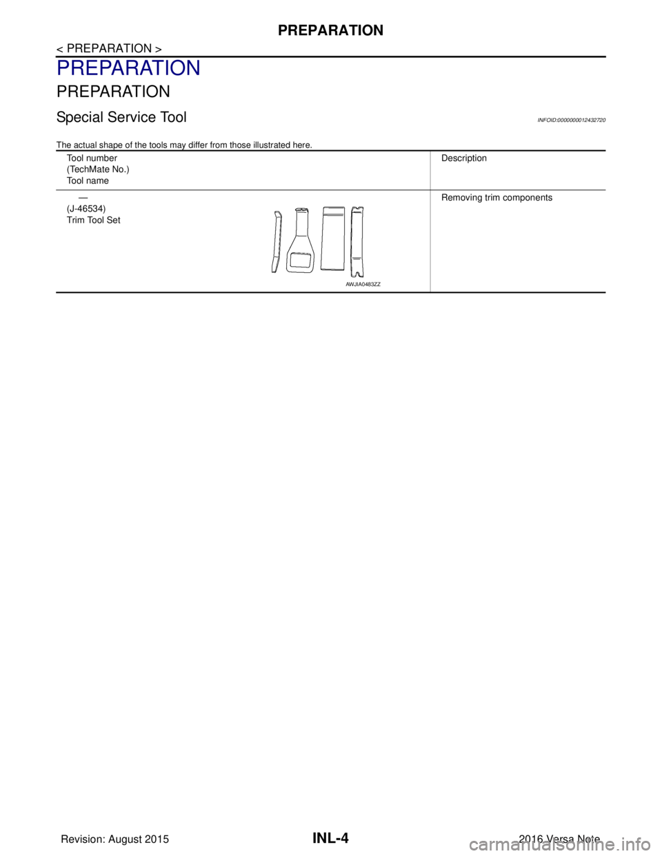
The actual shape of the tools may differ from those illustrated here.
Tool number
(TechMate No.)
Tool nameDescription
—
(J-46534)
Trim Tool Set Removing trim components
AWJIA0483ZZ
Revision: August 2015
2016 Versa Note
cardiagn.com
Page 2099 of 3641
COMPONENT PARTSINL-5
< SYSTEM DESCRIPTION >
C
DE
F
G H
I
J
K
M A
B
INL
N
O P
SYSTEM DESCRIPTION
COMPONENT PARTS
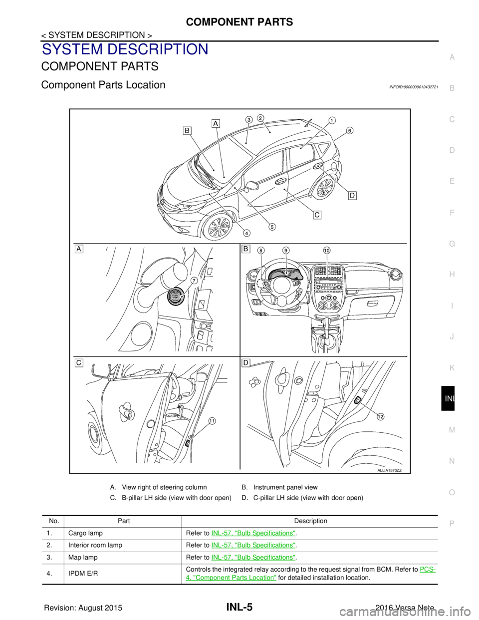
Component Parts LocationINFOID:0000000012432721
A. View right of steering column B. Instrument panel view
C. B-pillar LH side (view with door open) D. C-pillar LH side (view with door open)
No. Part Description
1. Cargo lamp Refer to INL-57, "
Bulb Specifications".
2. Interior room lamp Refer to INL-57, "
Bulb Specifications".
3. Map lamp Refer to INL-57, "
Bulb Specifications".
4. IPDM E/R Controls the integrated relay according to the request signal from BCM. Refer to
PCS-
4, "Component Parts Location" for detailed installation location.
ALLIA1570ZZ
Revision: August 2015 2016 Versa Note
cardiagn.com
Page 2100 of 3641
INL-6
< SYSTEM DESCRIPTION >
COMPONENT PARTS
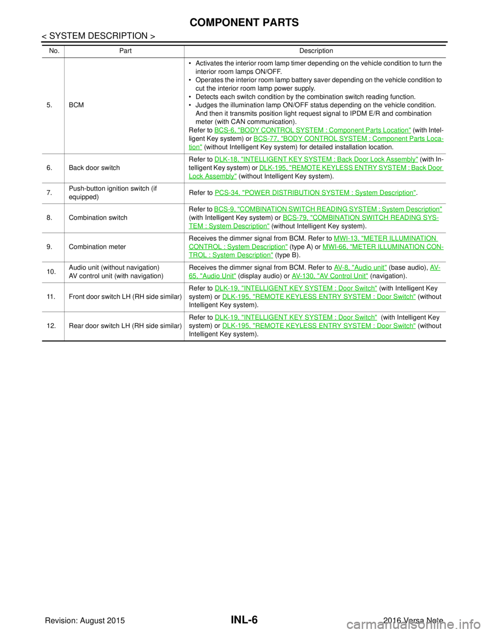
5. BCM• Activates the interior room lamp timer depending on the vehicle condition to turn the
interior room lamps ON/OFF.
• Operates the interior room lamp battery saver depending on the vehicle condition to cut the interior room lamp power supply.
• Detects each switch condition by the combination switch reading function.
• Judges the illumination lamp ON/OFF status depending on the vehicle condition.
And then it transmits position light request signal to IPDM E/R and combination
meter (with CAN communication).
Refer to BCS-6, "
BODY CONTROL SYSTEM : Component Part s Location" (with Intel-
ligent Key system) or BCS-77, "
BODY CONTROL SYSTEM : Component Parts Loca-
tion" (without Intelligent Key system) for detailed installation location.
6. Back door switch Refer to DLK-18, "
INTELLIGENT KEY SYSTEM : Ba
ck Door Lock Assembly" (with In-
telligent Key system) or DLK-195, "
REMOTE KEYLESS ENTRY SYSTEM : Back Door
Lock Assembly" (without Intelligent Key system).
7. Push-button ignition switch (if
equipped) Refer to PCS-34, "
POWER DISTRIBUTION SYSTEM : System Description".
8. Combination switch Refer to
BCS-9, "
COMBINATION SWITCH READING SY STEM : System Description"
(with Intelligent Key system) or BCS-79, "
COMBINATION SWITCH READING SYS-
TEM : System Description" (without Intelligent Key system).
9. Combination meter Receives the dimmer signal from BCM. Refer to
MWI-13, "
METER ILLUMINATION
CONTROL : System Description" (type A) or MWI-66, "METER ILLUMINATION CON-
TROL : System Description" (type B).
10. Audio unit (without navigation)
AV control unit (with navigation) Receives the dimmer signal from BCM. Refer to
AV- 8 , "
Audio unit" (base audio), AV-
65, "Audio Unit" (display audio) or AV- 1 3 0 , "AV Control Unit" (navigation).
11. Front door switch LH (RH side similar) Refer to DLK-19, "
INTELLIGENT KEY SYSTEM : Door Switch" (with Intelligent Key
system) or DLK-195, "
REMOTE KEYLESS ENTRY SYSTEM : Door Switch" (without
Intelligent Key system).
12. Rear door switch LH (RH side similar) Refer to DLK-19, "
INTELLIGENT KEY SYSTEM : Door Switch" (with Intelligent Key
system) or DLK-195, "
REMOTE KEYLESS ENTRY SYSTEM : Door Switch" (without
Intelligent Key system).
No.
Part Description
Revision: August 2015 2016 Versa Note
cardiagn.com