engine NISSAN PATROL 1998 Y61 / 5.G Engine Control Owners Manual
[x] Cancel search | Manufacturer: NISSAN, Model Year: 1998, Model line: PATROL, Model: NISSAN PATROL 1998 Y61 / 5.GPages: 192, PDF Size: 4.28 MB
Page 137 of 192

Fuel Temperature Sensor (FTS)
The fuel temperature sensor is used to detect the fuel temperature
in the injection pump. The sensor modi®es a voltage signal from the
ECM. The modi®ed signal returns to the ECM as the fuel tempera-
ture input. The sensor uses a thermistor which is sensitive to the
change in temperature. The electrical resistance of the thermistor
decreases as temperature increases.
Engine coolant tempera-
ture
ÉC (ÉF)Voltage
(V)Resistance
(kW)
þ20 (þ4) 4.6 13.67 - 16.37
20 (68) 3.5 2.306 - 2.568
60 (140) 1.8 0.538 - 0.624
80 (176) 1.2 0.289 - 0.344
ECM TERMINALS AND REFERENCE VALUE
Remarks: Speci®cation data are reference values and are measured between each terminal andV43(ECCS
ground) with a voltmeter.
TER-
MINAL
NO.WIRE
COLORITEM CONDITIONDATA
(DC Voltage and Pulse
Signal)
10 P Fuel temperature sensor Engine is running.
Approximately 0 - 4.8V
Output voltage varies with
fuel temperature.
50 B Sensors' groundEngine is running.
(Warm-up condition)
Idle speedApproximately 0V
ON BOARD DIAGNOSIS LOGIC
Diagnostic
Trouble Code
No.Malfunction is detected when ...Check Items
(Possible Cause)
42+An excessively high or low voltage from the sensor is
detected by ECM.+Harness or connectors
(The sensor circuit is open or shorted.)
+Fuel temperature sensor
DIAGNOSTIC TROUBLE CODE CONFIRMATION
PROCEDURE
1) Turn ignition switch ``ON''.
2) Select ``DATA MONITOR'' mode with CONSULT.
3) Wait at least 5 seconds.
-------------------------------------------------------------------------------------------------------------------------------------------------------------------------------------------------------------------------------------------------------OR-------------------------------------------------------------------------------------------------------------------------------------------------------------------------------------------------------------------------------------------------------
1) Turn ignition switch ``ON'' and wait at least 5 seconds.
2) Turn ignition switch ``OFF'', wait at least 5 seconds and
then turn ``ON''.
3) Perform ``Diagnostic Test Mode II (Self-diagnostic
results)'' with ECM.
SEF666S
SEF012P
SEF748V
TROUBLE DIAGNOSIS FOR ``FUEL TEMP SENSOR'' (DTC 42)
EC-135
Page 139 of 192

DIAGNOSTIC PROCEDURE
INSPECTION START
CHECK POWER SUPPLY.
1. Turn ignition switch ``OFF''.
2. Disconnect electronic fuel injection
pump harness connector.
3. Turn ignition switch ``ON''.
4. Check voltage between terminal
V1
and ground with CONSULT or tester.
Voltage:
Approximately 5V
OK
cNG
Repair harness or connec-
tors.
CHECK GROUND CIRCUIT.
1. Turn ignition switch ``OFF''.
2. Check harness continuity between ter-
minal
V5and engine ground.
Continuity should exist.
If OK, check harness for short to
ground and short to power.
OK
cNG
Check the following.
+Harness connectors
F6,M51
+Harness connectors
M88,E106
+Harness for open or
short between ECM and
electronic fuel injection
pump
+Harness for open or
short between TCM and
electronic fuel injection
pump
If NG, repair open circuit or
short to ground or short to
power in harness or con-
nectors.
CHECK COMPONENT
(Fuel temperature sensor).
Refer to ``COMPONENT INSPECTION''
on next page.
OK
cNG
Take proper action.
Disconnect and reconnect harness con-
nectors in the circuits. Then retest.
Trouble is not ®xed.
Check ECM pin terminals for damage and
check the connection of ECM harness
connector. Reconnect ECM harness con-
nector and retest.
INSPECTION END
SEF682VB
SEF769V
SEF770V
.
.
.
.
.
.
TROUBLE DIAGNOSIS FOR ``FUEL TEMP SENSOR'' (DTC 42)
Fuel Temperature Sensor (FTS) (Cont'd)
EC-137
Page 141 of 192

Accelerator Position Sensor
The accelerator position sensor is installed on the upper end of the
accelerator pedal assembly. The sensor detects the accelerator
position and sends a signal to the ECM. The ECM uses the signal
to determine the amount of fuel to be injected.
CONSULT REFERENCE VALUE IN DATA MONITOR MODE
Remarks: Speci®cation data are reference values.
MONITOR ITEM CONDITION SPECIFICATION
ACCEL POS SEN+Ignition switch: ON
(Engine stopped)Accelerator pedal: released 0.40 - 0.60V
Accelerator pedal: depressed Approx. 4.0V
ECM TERMINALS AND REFERENCE VALUE
Remarks: Speci®cation data are reference values and are measured between each terminal andV43(ECCS
ground) with a voltmeter.
TER-
MINAL
NO.WIRE
COLORITEM CONDITIONDATA
(DC Voltage and Pulse
Signal)
23 WAccelerator position sen-
sorIgnition switch ``ON''
Accelerator pedal fully released0.4 - 0.6V
Ignition switch ``ON''
Accelerator pedal fully depressedApproximately 4.3V
48 G/RAccelerator position sen-
sor power supplyIgnition switch ``ON''
Approximately 5V
51 L/WAccelerator position sen-
sor groundEngine is running.
(Warm-up condition)
Idle speedApproximately 0V
SEF861SA
TROUBLE DIAGNOSIS FOR ``ACCEL POS SENSOR'' (DTC 43)
EC-139
Page 144 of 192

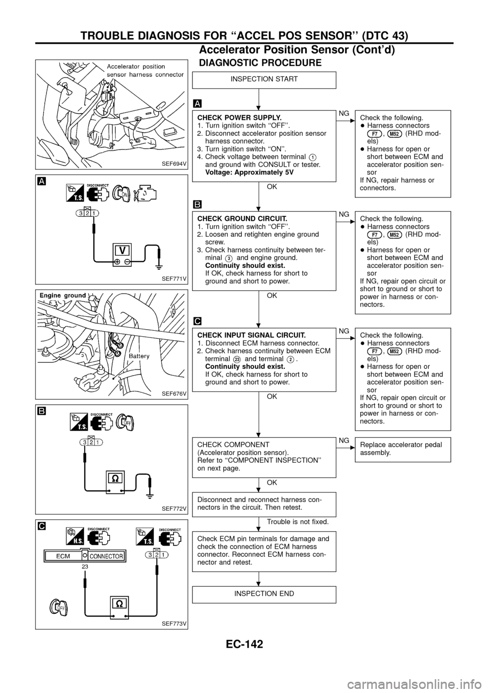
DIAGNOSTIC PROCEDURE
INSPECTION START
CHECK POWER SUPPLY.
1. Turn ignition switch ``OFF''.
2. Disconnect accelerator position sensor
harness connector.
3. Turn ignition switch ``ON''.
4. Check voltage between terminal
V1and ground with CONSULT or tester.
Voltage: Approximately 5V
OK
cNG
Check the following.
+Harness connectors
F7,M52(RHD mod-
els)
+Harness for open or
short between ECM and
accelerator position sen-
sor
If NG, repair harness or
connectors.
CHECK GROUND CIRCUIT.
1. Turn ignition switch ``OFF''.
2. Loosen and retighten engine ground
screw.
3. Check harness continuity between ter-
minal
V3and engine ground.
Continuity should exist.
If OK, check harness for short to
ground and short to power.
OK
cNG
Check the following.
+Harness connectors
F7,M52(RHD mod-
els)
+Harness for open or
short between ECM and
accelerator position sen-
sor
If NG, repair open circuit or
short to ground or short to
power in harness or con-
nectors.
CHECK INPUT SIGNAL CIRCUIT.
1. Disconnect ECM harness connector.
2. Check harness continuity between ECM
terminal
V23and terminalV2.
Continuity should exist.
If OK, check harness for short to
ground and short to power.
OK
cNG
Check the following.
+Harness connectors
F7,M52(RHD mod-
els)
+Harness for open or
short between ECM and
accelerator position sen-
sor
If NG, repair open circuit or
short to ground or short to
power in harness or con-
nectors.
CHECK COMPONENT
(Accelerator position sensor).
Refer to ``COMPONENT INSPECTION''
on next page.
OK
cNG
Replace accelerator pedal
assembly.
Disconnect and reconnect harness con-
nectors in the circuit. Then retest.
Trouble is not ®xed.
Check ECM pin terminals for damage and
check the connection of ECM harness
connector. Reconnect ECM harness con-
nector and retest.
INSPECTION END
SEF694V
SEF771V
SEF676V
SEF772V
SEF773V
.
.
.
.
.
.
.
TROUBLE DIAGNOSIS FOR ``ACCEL POS SENSOR'' (DTC 43)
Accelerator Position Sensor (Cont'd)
EC-142
Page 145 of 192

COMPONENT INSPECTION
Accelerator position sensor
1. Disconnect accelerator position sensor harness connector.
2. Make sure that resistance between terminals
V2andV3
changes when depressing accelerator pedal manually.
Accelerator pedal conditions Resistance [at 25ÉC (77ÉF)]
Completely released Approximately 0.5 kW
Partially depressed 0.5-4kW
Completely depressed Approximately 4 kW
If NG, replace accelerator pedal assembly.
CAUTION:
If accelerator position sensor or ECM connector is
disconnected, perform the following procedures:
Select ``OFF ACCEL PO SIG'' in ``ACTIVE TEST'' mode.
Touch CLEAR.
-------------------------------------------------------------------------------------------------------------------------------------------------------------------------------------------------------------------------------------------------------OR-------------------------------------------------------------------------------------------------------------------------------------------------------------------------------------------------------------------------------------------------------
Start and warm up engine. After engine has warmed up,
idle for 10 minutes.
SEF695V
TROUBLE DIAGNOSIS FOR ``ACCEL POS SENSOR'' (DTC 43)
Accelerator Position Sensor (Cont'd)
EC-143
Page 146 of 192

Crankshaft Position Sensor (TDC)
The crankshaft position sensor (TDC) monitors engine speed by
means of signals from the sensing plate (with two protrusions)
installed to the crankshaft pulley. The datum signal output is
detected at ATDC 70É and sent to the ECM. The sensor signal is
used for fuel injection control and fuel injection timing control.
CONSULT REFERENCE VALUE IN DATA MONITOR MODE
Remarks: Speci®cation data are reference values.
MONITOR ITEM CONDITION SPECIFICATION
CKPSzRPM (TDC)+Tachometer: Connect
+Run engine and compare tachometer indication with the CONSULT
value.Almost the same speed as the
CONSULT value.
ECM TERMINALS AND REFERENCE VALUE
Remarks: Speci®cation data are reference values and are measured between each terminal andV43(ECCS
ground) with a voltmeter.
TER-
MINAL
NO.WIRE
COLORITEM CONDITIONDATA
(DC Voltage and Pulse
Signal)
40
44LCrankshaft position sensor
(TDC)Engine is running.
(Warm-up condition)
Idle speedApproximately 0V
SEF720V
Engine is running.(Warm-up condition)
Engine speed is 2,000 rpm.Approximately 0V
SEF721V
47
52B/WCrankshaft position sensor
(TDC) groundEngine is running.(Warm-up condition)
Idle speedApproximately 0V
ON BOARD DIAGNOSIS LOGIC
Diagnostic
Trouble Code
No.Malfunction is detected when ....Check Items
(Possible Cause)
47+An improper signal from the sensor is detected by
ECM during engine running and cranking.+Harness or connectors
(The sensor circuit is open.)
+Crankshaft position sensor (TDC)
SEF615S
TROUBLE DIAGNOSIS FOR ``CRANK POS SEN (TDC)'' (DTC 47)
EC-144
Page 147 of 192

DIAGNOSTIC TROUBLE CODE CONFIRMATION
PROCEDURE
Before performing the following procedure, con®rm that bat-
tery voltage is more than 10V.
1) Turn ignition switch ``ON'' and select ``DATA MONITOR''
mode with CONSULT.
2) Crank engine for at least 1 second.
3) Start engine and run it for at least 2 seconds at idle
speed.
-------------------------------------------------------------------------------------------------------------------------------------------------------------------------------------------------------------------------------------------------------OR-------------------------------------------------------------------------------------------------------------------------------------------------------------------------------------------------------------------------------------------------------
1) Crank engine for at least 1 second.
2) Start engine and run it for at least 2 seconds at idle
speed.
3) Turn ignition switch ``OFF'', wait at least 5 seconds and
then turn ``ON''.
4) Perform ``Diagnostic Test Mode II (Self-diagnostic
results)'' with ECM.SEF714V
TROUBLE DIAGNOSIS FOR ``CRANK POS SEN (TDC)'' (DTC 47)
Crankshaft Position Sensor (TDC) (Cont'd)
EC-145
Page 149 of 192

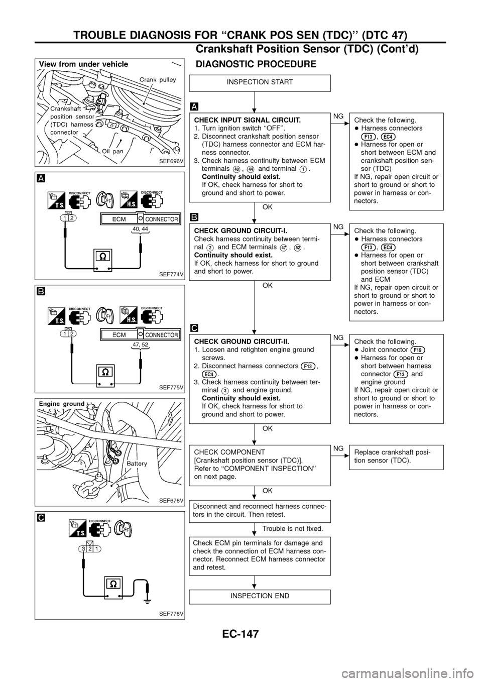
DIAGNOSTIC PROCEDURE
INSPECTION START
CHECK INPUT SIGNAL CIRCUIT.
1. Turn ignition switch ``OFF''.
2. Disconnect crankshaft position sensor
(TDC) harness connector and ECM har-
ness connector.
3. Check harness continuity between ECM
terminals
V40,V44and terminalV1.
Continuity should exist.
If OK, check harness for short to
ground and short to power.
OK
cNG
Check the following.
+Harness connectors
F13,EC4+Harness for open or
short between ECM and
crankshaft position sen-
sor (TDC)
If NG, repair open circuit or
short to ground or short to
power in harness or con-
nectors.
CHECK GROUND CIRCUIT-I.
Check harness continuity between termi-
nal
V2and ECM terminalsV47,V52.
Continuity should exist.
If OK, check harness for short to ground
and short to power.
OK
cNG
Check the following.
+Harness connectors
F13,EC4+Harness for open or
short between crankshaft
position sensor (TDC)
and ECM
If NG, repair open circuit or
short to ground or short to
power in harness or con-
nectors.
CHECK GROUND CIRCUIT-II.
1. Loosen and retighten engine ground
screws.
2. Disconnect harness connectors
F13,EC4.
3. Check harness continuity between ter-
minal
V3and engine ground.
Continuity should exist.
If OK, check harness for short to
ground and short to power.
OK
cNG
Check the following.
+Joint connector
F19+Harness for open or
short between harness
connector
F13and
engine ground
If NG, repair open circuit or
short to ground or short to
power in harness or con-
nectors.
CHECK COMPONENT
[Crankshaft position sensor (TDC)].
Refer to ``COMPONENT INSPECTION''
on next page.
OK
cNG
Replace crankshaft posi-
tion sensor (TDC).
Disconnect and reconnect harness connec-
tors in the circuit. Then retest.
Trouble is not ®xed.
Check ECM pin terminals for damage and
check the connection of ECM harness con-
nector. Reconnect ECM harness connector
and retest.
INSPECTION END
SEF696V
SEF774V
SEF775V
SEF676V
SEF776V
.
.
.
.
.
.
.
TROUBLE DIAGNOSIS FOR ``CRANK POS SEN (TDC)'' (DTC 47)
Crankshaft Position Sensor (TDC) (Cont'd)
EC-147
Page 151 of 192

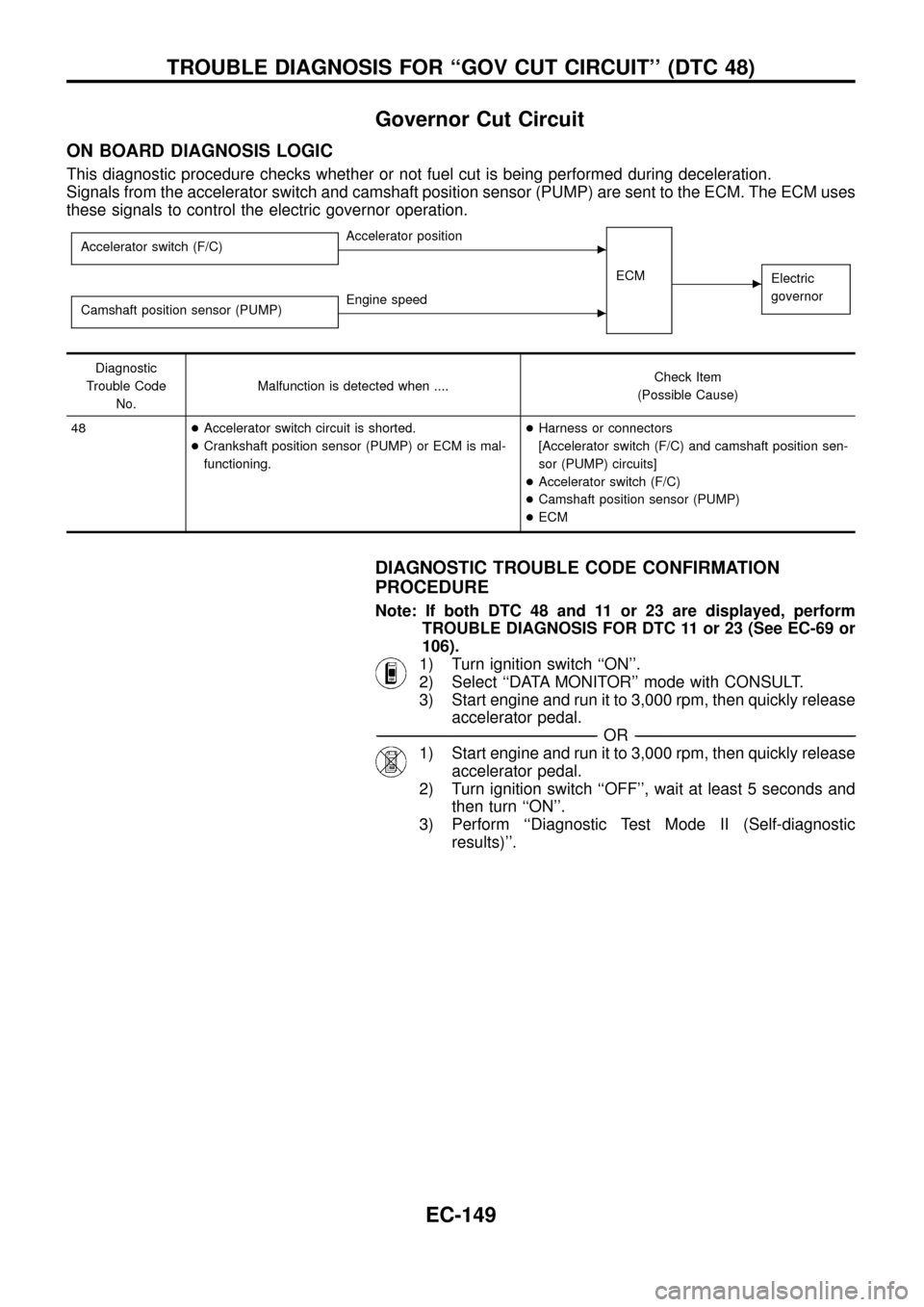
Governor Cut Circuit
ON BOARD DIAGNOSIS LOGIC
This diagnostic procedure checks whether or not fuel cut is being performed during deceleration.
Signals from the accelerator switch and camshaft position sensor (PUMP) are sent to the ECM. The ECM uses
these signals to control the electric governor operation.
Accelerator switch (F/C)cAccelerator position
ECM
cElectric
governor
Camshaft position sensor (PUMP)cEngine speed
Diagnostic
Trouble Code
No.Malfunction is detected when ....Check Item
(Possible Cause)
48+Accelerator switch circuit is shorted.
+Crankshaft position sensor (PUMP) or ECM is mal-
functioning.+Harness or connectors
[Accelerator switch (F/C) and camshaft position sen-
sor (PUMP) circuits]
+Accelerator switch (F/C)
+Camshaft position sensor (PUMP)
+ECM
DIAGNOSTIC TROUBLE CODE CONFIRMATION
PROCEDURE
Note: If both DTC 48 and 11 or 23 are displayed, perform
TROUBLE DIAGNOSIS FOR DTC 11 or 23 (See EC-69 or
106).
1) Turn ignition switch ``ON''.
2) Select ``DATA MONITOR'' mode with CONSULT.
3) Start engine and run it to 3,000 rpm, then quickly release
accelerator pedal.
-------------------------------------------------------------------------------------------------------------------------------------------------------------------------------------------------------------------------------------------------------OR-------------------------------------------------------------------------------------------------------------------------------------------------------------------------------------------------------------------------------------------------------
1) Start engine and run it to 3,000 rpm, then quickly release
accelerator pedal.
2) Turn ignition switch ``OFF'', wait at least 5 seconds and
then turn ``ON''.
3) Perform ``Diagnostic Test Mode II (Self-diagnostic
results)''.
TROUBLE DIAGNOSIS FOR ``GOV CUT CIRCUIT'' (DTC 48)
EC-149
Page 153 of 192

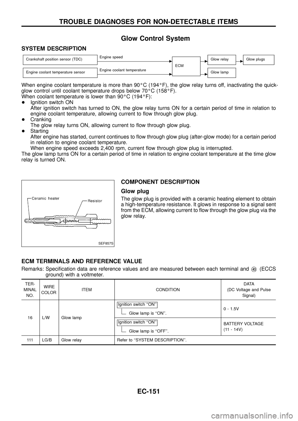
Glow Control System
SYSTEM DESCRIPTION
Crankshaft position sensor (TDC)cEngine speed
ECMcGlow relaycGlow plugs
Engine coolant temperature sensorcEngine coolant temperaturecGlow lamp
When engine coolant temperature is more than 90ÉC (194ÉF), the glow relay turns off, inactivating the quick-
glow control until coolant temperature drops below 70ÉC (158ÉF).
When coolant temperature is lower than 90ÉC (194ÉF):
+Ignition switch ON
After ignition switch has turned to ON, the glow relay turns ON for a certain period of time in relation to
engine coolant temperature, allowing current to ¯ow through glow plug.
+Cranking
The glow relay turns ON, allowing current to ¯ow through glow plug.
+Starting
After engine has started, current continues to ¯ow through glow plug (after-glow mode) for a certain period
in relation to engine coolant temperature.
When engine speed exceeds 2,400 rpm, current ¯ow through glow plug is interrupted.
The glow lamp turns ON for a certain period of time in relation to engine coolant temperature at the time glow
relay is turned ON.
COMPONENT DESCRIPTION
Glow plug
The glow plug is provided with a ceramic heating element to obtain
a high-temperature resistance. It glows in response to a signal sent
from the ECM, allowing current to ¯ow through the glow plug via the
glow relay.
ECM TERMINALS AND REFERENCE VALUE
Remarks: Speci®cation data are reference values and are measured between each terminal andV43(ECCS
ground) with a voltmeter.
TER-
MINAL
NO.WIRE
COLORITEM CONDITIONDATA
(DC Voltage and Pulse
Signal)
16 L/W Glow lampIgnition switch ``ON''
Glow lamp is ``ON''.0 - 1.5V
Ignition switch ``ON''
Glow lamp is ``OFF''.BATTERY VOLTAGE
(11 - 14V)
111 LG/B Glow relay Refer to ``SYSTEM DESCRIPTION''.
SEF857S
TROUBLE DIAGNOSES FOR NON-DETECTABLE ITEMS
EC-151