sensor NISSAN PATROL 1998 Y61 / 5.G Engine Control Owner's Manual
[x] Cancel search | Manufacturer: NISSAN, Model Year: 1998, Model line: PATROL, Model: NISSAN PATROL 1998 Y61 / 5.GPages: 192, PDF Size: 4.28 MB
Page 52 of 192
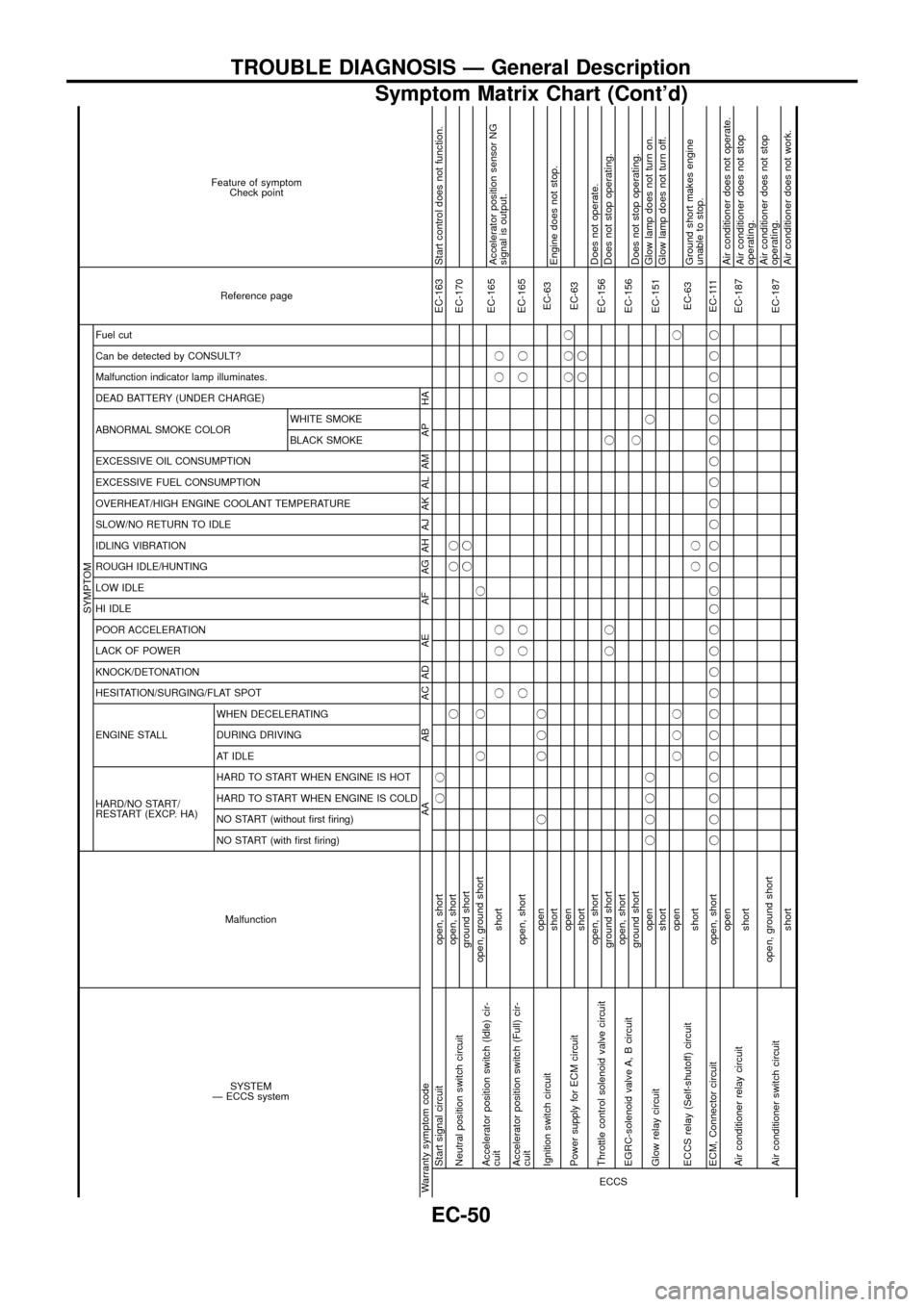
SYSTEM
Ð ECCS systemMalfunction
SYMPTOM
Reference page Feature of symptom
Check point
HARD/NO START/
RESTART (EXCP. HA) ENGINE STALL HESITATION/SURGING/FLAT SPOT KNOCK/DETONATION
LACK OF POWER
POOR ACCELERATION
HI IDLE
LOW IDLE
ROUGH IDLE/HUNTING
IDLING VIBRATION
SLOW/NO RETURN TO IDLE
OVERHEAT/HIGH ENGINE COOLANT TEMPERATURE
EXCESSIVE FUEL CONSUMPTION
EXCESSIVE OIL CONSUMPTION ABNORMAL SMOKE COLOR
DEAD BATTERY (UNDER CHARGE) Malfunction indicator lamp illuminates.
Can be detected by CONSULT?
Fuel cut
NO START (with ®rst ®ring) NO START (without ®rst ®ring)
HARD TO START WHEN ENGINE IS COLD
HARD TO START WHEN ENGINE IS HOT
AT IDLE
DURING DRIVING
WHEN DECELERATINGBLACK SMOKE WHITE SMOKE
Warranty symptom code AA AB AC AD AE AF AG AH AJ AK AL AM AP HAECCS
Start signal circuit open, shortjjEC-163 Start control does not function.
Neutral position switch circuitopen, shortjjj
EC-170
ground shortjj
Accelerator position switch (Idle) cir-
cuitopen, ground shortjj j
EC-165
shortjjj jjAccelerator position sensor NG
signal is output.
Accelerator position switch (Full) cir-
cuitopen, shortjjj jjEC-165
Ignition switch circuitopenj jjj
EC-63
shortEngine does not stop.
Power supply for ECM circuitopenjjj
EC-63
shortjj
Throttle control solenoid valve circuitopen, short
EC-156Does not operate.
ground shortjj jDoes not stop operating.
EGRC-solenoid valve A, B circuitopen, short
EC-156
ground shortjDoes not stop operating.
Glow relay circuitopenjjjjj
EC-151Glow lamp does not turn on.
shortGlow lamp does not turn off.
ECCS relay (Self-shutoff) circuitopenjjjj
EC-63
shortjjGround short makes engine
unable to stop.
ECM, Connector circuit open, shortjjjjjjjjjjjjj jjjjjjjjjjjjEC-111
Air conditioner relay circuitopen
EC-187Air conditioner does not operate.
shortAir conditioner does not stop
operating.
Air conditioner switch circuitopen, ground short
EC-187Air conditioner does not stop
operating.
shortAir conditioner does not work.
TROUBLE DIAGNOSIS Ð General Description
Symptom Matrix Chart (Cont'd)
EC-50
Page 55 of 192
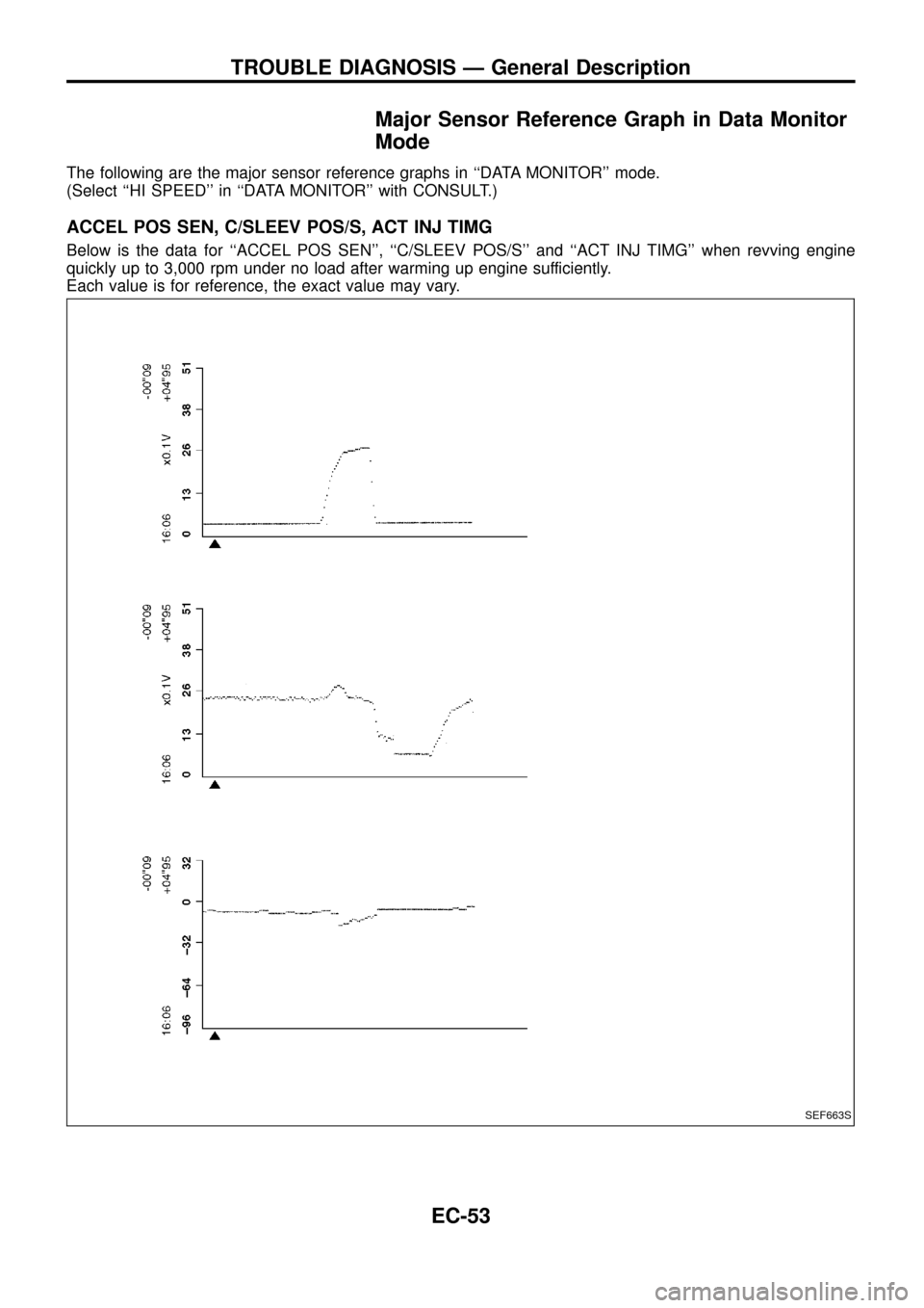
Major Sensor Reference Graph in Data Monitor
Mode
The following are the major sensor reference graphs in ``DATA MONITOR'' mode.
(Select ``HI SPEED'' in ``DATA MONITOR'' with CONSULT.)
ACCEL POS SEN, C/SLEEV POS/S, ACT INJ TIMG
Below is the data for ``ACCEL POS SEN'', ``C/SLEEV POS/S'' and ``ACT INJ TIMG'' when revving engine
quickly up to 3,000 rpm under no load after warming up engine sufficiently.
Each value is for reference, the exact value may vary.
SEF663S
TROUBLE DIAGNOSIS Ð General Description
EC-53
Page 58 of 192
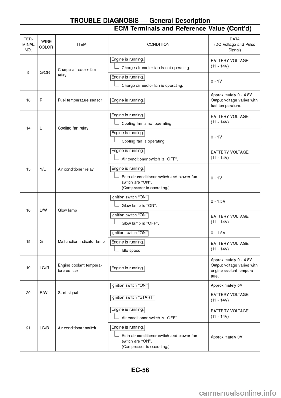
TER-
MINAL
NO.WIRE
COLORITEM CONDITIONDATA
(DC Voltage and Pulse
Signal)
8 G/ORCharge air cooler fan
relayEngine is running.
Charge air cooler fan is not operating.BATTERY VOLTAGE
(11 - 14V)
Engine is running.
Charge air cooler fan is operating.0-1V
10 P Fuel temperature sensor Engine is running.
Approximately 0 - 4.8V
Output voltage varies with
fuel temperature.
14 L Cooling fan relayEngine is running.
Cooling fan is not operating.BATTERY VOLTAGE
(11 - 14V)
Engine is running.
Cooling fan is operating.0-1V
15 Y/L Air conditioner relayEngine is running.
Air conditioner switch is ``OFF''.BATTERY VOLTAGE
(11 - 14V)
Engine is running.
Both air conditioner switch and blower fan
switch are ``ON''.
(Compressor is operating.)0-1V
16 L/W Glow lampIgnition switch ``ON''
Glow lamp is ``ON''.0 - 1.5V
Ignition switch ``ON''
Glow lamp is ``OFF''.BATTERY VOLTAGE
(11 - 14V)
18 G Malfunction indicator lampIgnition switch ``ON''
0 - 1.5V
Engine is running.
Idle speedBATTERY VOLTAGE
(11 - 14V)
19 LG/REngine coolant tempera-
ture sensorEngine is running.
Approximately 0 - 4.8V
Output voltage varies with
engine coolant tempera-
ture.
20 R/W Start signalIgnition switch ``ON''
Approximately 0V
Ignition switch ``START''
BATTERY VOLTAGE
(11 - 14V)
21 LG/B Air conditioner switchEngine is running.
Air conditioner switch is ``OFF''.BATTERY VOLTAGE
(11 - 14V)
Engine is running.
Both air conditioner switch and blower fan
switch are ``ON''.
(Compressor is operating.)Approximately 0V
TROUBLE DIAGNOSIS Ð General Description
ECM Terminals and Reference Value (Cont'd)
EC-56
Page 59 of 192
TER-
MINAL
NO.WIRE
COLORITEM CONDITIONDATA
(DC Voltage and Pulse
Signal)
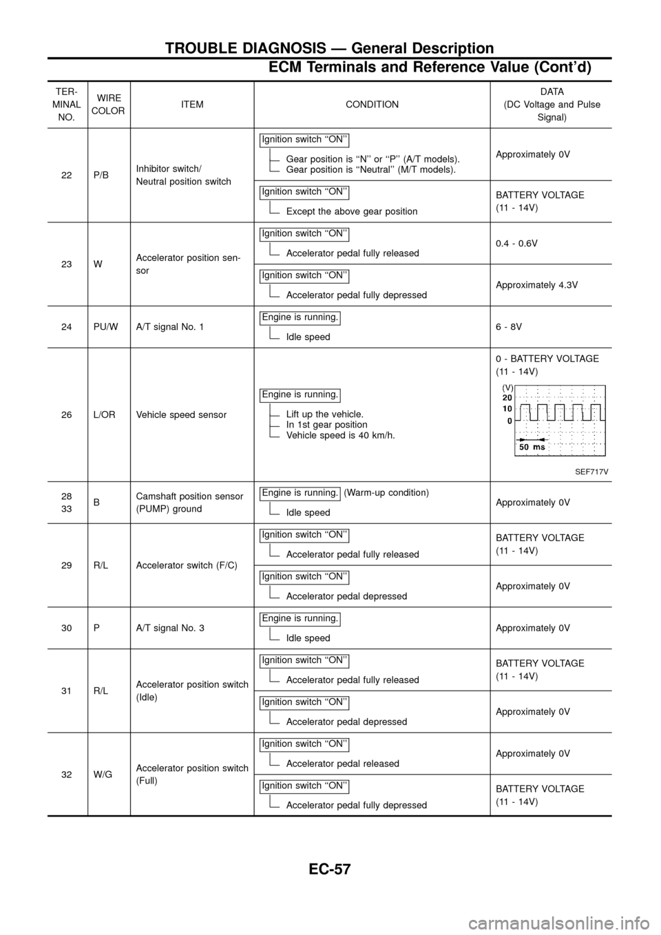
22 P/BInhibitor switch/
Neutral position switchIgnition switch ``ON''
Gear position is ``N'' or ``P'' (A/T models).Gear position is ``Neutral'' (M/T models).Approximately 0V
Ignition switch ``ON''
Except the above gear positionBATTERY VOLTAGE
(11 - 14V)
23 WAccelerator position sen-
sorIgnition switch ``ON''
Accelerator pedal fully released0.4 - 0.6V
Ignition switch ``ON''
Accelerator pedal fully depressedApproximately 4.3V
24 PU/W A/T signal No. 1Engine is running.
Idle speed6-8V
26 L/OR Vehicle speed sensorEngine is running.
Lift up the vehicle.In 1st gear positionVehicle speed is 40 km/h.0 - BATTERY VOLTAGE
(11 - 14V)
SEF717V
28
33BCamshaft position sensor
(PUMP) groundEngine is running.(Warm-up condition)
Idle speedApproximately 0V
29 R/L Accelerator switch (F/C)Ignition switch ``ON''
Accelerator pedal fully releasedBATTERY VOLTAGE
(11 - 14V)
Ignition switch ``ON''
Accelerator pedal depressedApproximately 0V
30 P A/T signal No. 3Engine is running.
Idle speedApproximately 0V
31 R/LAccelerator position switch
(Idle)Ignition switch ``ON''
Accelerator pedal fully releasedBATTERY VOLTAGE
(11 - 14V)
Ignition switch ``ON''
Accelerator pedal depressedApproximately 0V
32 W/GAccelerator position switch
(Full)Ignition switch ``ON''
Accelerator pedal releasedApproximately 0V
Ignition switch ``ON''
Accelerator pedal fully depressedBATTERY VOLTAGE
(11 - 14V)
TROUBLE DIAGNOSIS Ð General Description
ECM Terminals and Reference Value (Cont'd)
EC-57
Page 60 of 192
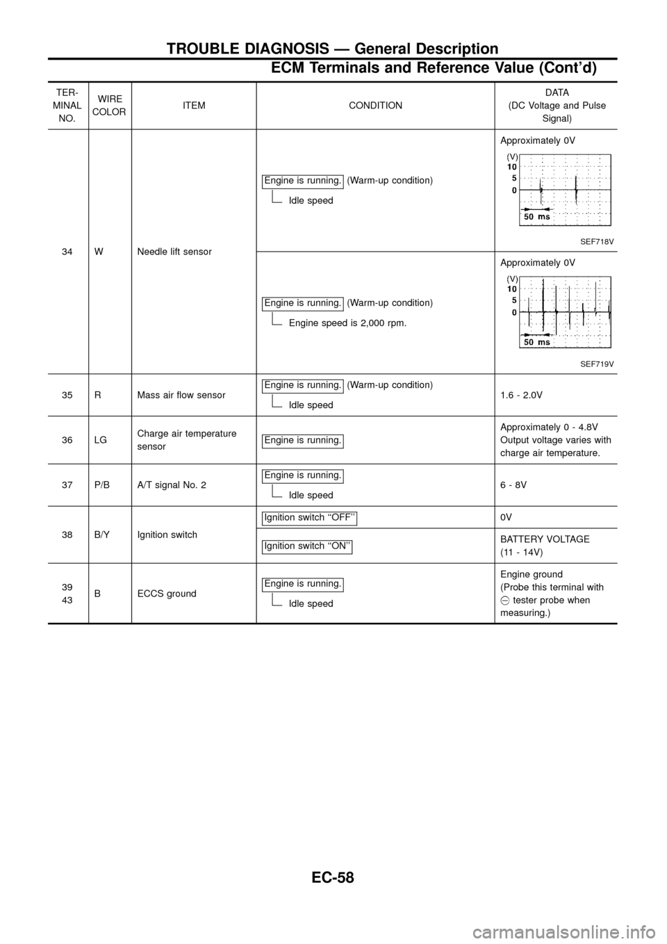
TER-
MINAL
NO.WIRE
COLORITEM CONDITIONDATA
(DC Voltage and Pulse
Signal)
34 W Needle lift sensorEngine is running.
(Warm-up condition)
Idle speedApproximately 0V
SEF718V
Engine is running.(Warm-up condition)
Engine speed is 2,000 rpm.Approximately 0V
SEF719V
35 R Mass air ¯ow sensorEngine is running.(Warm-up condition)
Idle speed1.6 - 2.0V
36 LGCharge air temperature
sensorEngine is running.
Approximately 0 - 4.8V
Output voltage varies with
charge air temperature.
37 P/B A/T signal No. 2Engine is running.
Idle speed6-8V
38 B/Y Ignition switchIgnition switch ``OFF''
0V
Ignition switch ``ON''
BATTERY VOLTAGE
(11 - 14V)
39
43B ECCS groundEngine is running.
Idle speedEngine ground
(Probe this terminal with
@tester probe when
measuring.)
TROUBLE DIAGNOSIS Ð General Description
ECM Terminals and Reference Value (Cont'd)
EC-58
Page 61 of 192
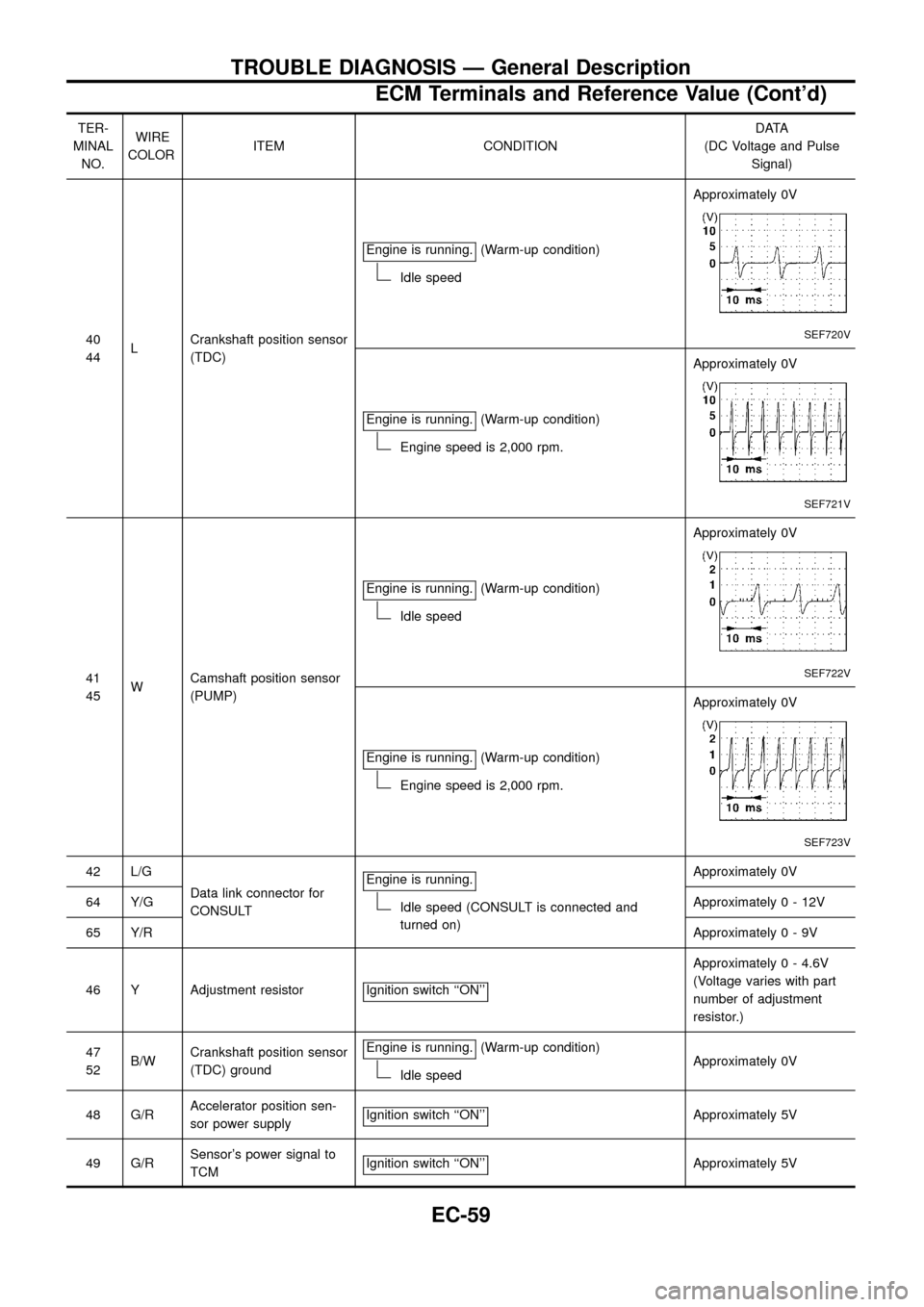
TER-
MINAL
NO.WIRE
COLORITEM CONDITIONDATA
(DC Voltage and Pulse
Signal)
40
44LCrankshaft position sensor
(TDC)Engine is running.
(Warm-up condition)
Idle speedApproximately 0V
SEF720V
Engine is running.(Warm-up condition)
Engine speed is 2,000 rpm.Approximately 0V
SEF721V
41
45WCamshaft position sensor
(PUMP)Engine is running.
(Warm-up condition)
Idle speedApproximately 0V
SEF722V
Engine is running.(Warm-up condition)
Engine speed is 2,000 rpm.Approximately 0V
SEF723V
42 L/G
Data link connector for
CONSULTEngine is running.
Idle speed (CONSULT is connected and
turned on)Approximately 0V
64 Y/GApproximately0-12V
65 Y/RApproximately0-9V
46 Y Adjustment resistor Ignition switch ``ON''
Approximately 0 - 4.6V
(Voltage varies with part
number of adjustment
resistor.)
47
52B/WCrankshaft position sensor
(TDC) groundEngine is running.
(Warm-up condition)
Idle speedApproximately 0V
48 G/RAccelerator position sen-
sor power supplyIgnition switch ``ON''
Approximately 5V
49 G/RSensor's power signal to
TCMIgnition switch ``ON''
Approximately 5V
TROUBLE DIAGNOSIS Ð General Description
ECM Terminals and Reference Value (Cont'd)
EC-59
Page 62 of 192
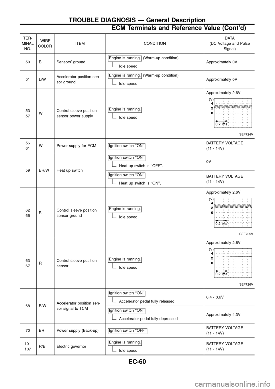
TER-
MINAL
NO.WIRE
COLORITEM CONDITIONDATA
(DC Voltage and Pulse
Signal)
50 B Sensors' groundEngine is running.
(Warm-up condition)
Idle speedApproximately 0V
51 L/WAccelerator position sen-
sor groundEngine is running.
(Warm-up condition)
Idle speedApproximately 0V
53
57WControl sleeve position
sensor power supplyEngine is running.
Idle speedApproximately 2.6V
SEF724V
56
61W Power supply for ECM Ignition switch ``ON''BATTERY VOLTAGE
(11 - 14V)
59 BR/W Heat up switchIgnition switch ``ON''
Heat up switch is ``OFF''.0V
Ignition switch ``ON''
Heat up switch is ``ON''.BATTERY VOLTAGE
(11 - 14V)
62
66BControl sleeve position
sensor groundEngine is running.
Idle speedApproximately 2.6V
SEF725V
63
67RControl sleeve position
sensorEngine is running.
Idle speedApproximately 2.6V
SEF726V
68 B/WAccelerator position sen-
sor signal to TCMIgnition switch ``ON''Accelerator pedal fully released0.4 - 0.6V
Ignition switch ``ON''
Accelerator pedal fully depressedApproximately 4.3V
70 BR Power supply (Back-up) Ignition switch ``OFF''
BATTERY VOLTAGE
(11 - 14V)
101
107R/B Electric governorEngine is running.
Idle speedBATTERY VOLTAGE
(11 - 14V)
TROUBLE DIAGNOSIS Ð General Description
ECM Terminals and Reference Value (Cont'd)
EC-60
Page 71 of 192
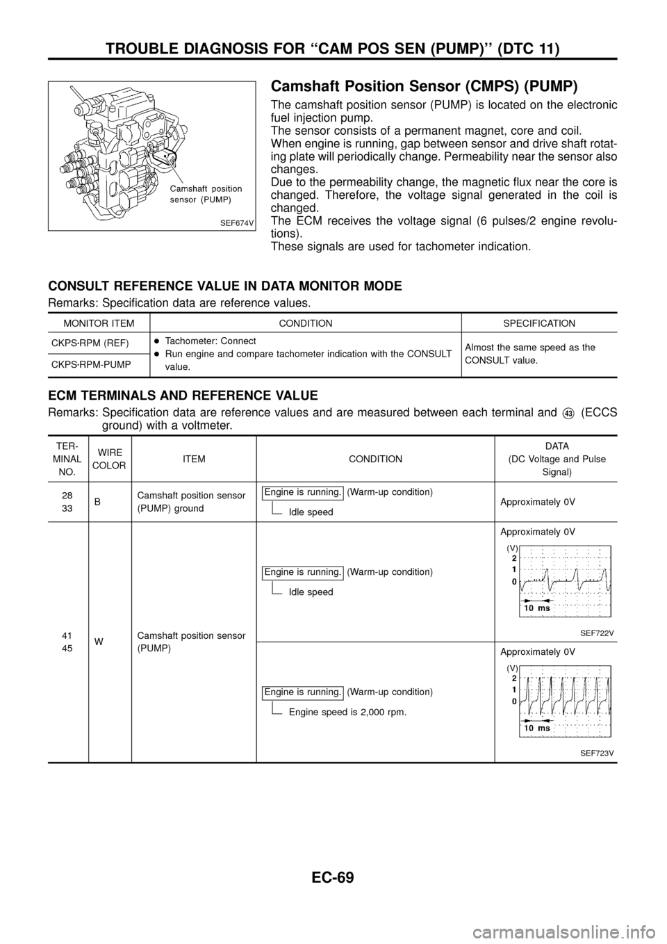
Camshaft Position Sensor (CMPS) (PUMP)
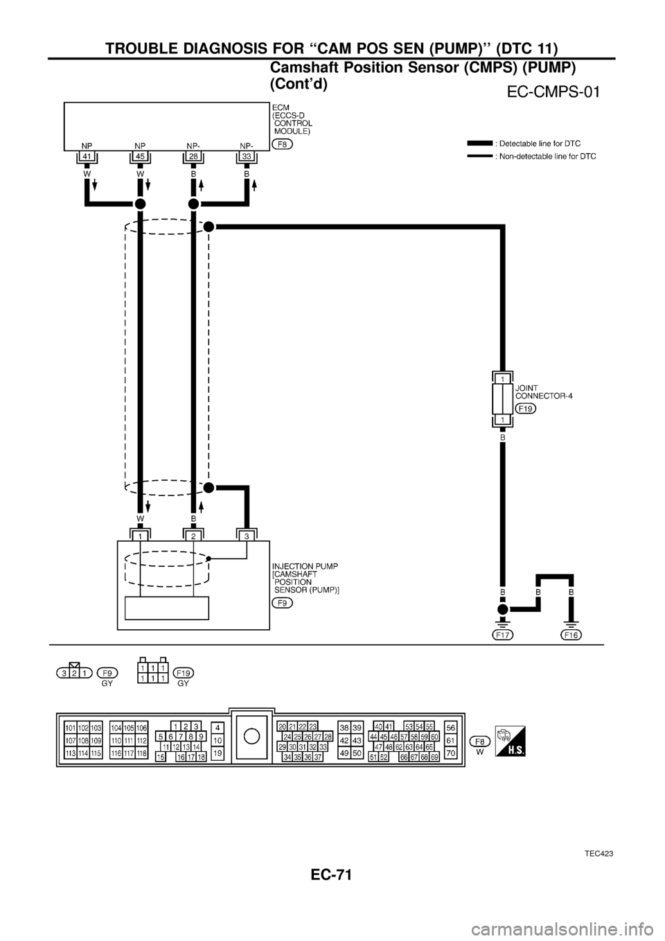
The camshaft position sensor (PUMP) is located on the electronic
fuel injection pump.
The sensor consists of a permanent magnet, core and coil.
When engine is running, gap between sensor and drive shaft rotat-
ing plate will periodically change. Permeability near the sensor also
changes.
Due to the permeability change, the magnetic ¯ux near the core is
changed. Therefore, the voltage signal generated in the coil is
changed.
The ECM receives the voltage signal (6 pulses/2 engine revolu-
tions).
These signals are used for tachometer indication.
CONSULT REFERENCE VALUE IN DATA MONITOR MODE
Remarks: Speci®cation data are reference values.
MONITOR ITEM CONDITION SPECIFICATION
CKPSzRPM (REF)+Tachometer: Connect
+Run engine and compare tachometer indication with the CONSULT
value.Almost the same speed as the
CONSULT value.
CKPSzRPM-PUMP
ECM TERMINALS AND REFERENCE VALUE
Remarks: Speci®cation data are reference values and are measured between each terminal andV43(ECCS
ground) with a voltmeter.
TER-
MINAL
NO.WIRE
COLORITEM CONDITIONDATA
(DC Voltage and Pulse
Signal)
28
33BCamshaft position sensor
(PUMP) groundEngine is running.
(Warm-up condition)
Idle speedApproximately 0V
41
45WCamshaft position sensor
(PUMP)Engine is running.
(Warm-up condition)
Idle speedApproximately 0V
SEF722V
Engine is running.(Warm-up condition)
Engine speed is 2,000 rpm.Approximately 0V
SEF723V
SEF674V
TROUBLE DIAGNOSIS FOR ``CAM POS SEN (PUMP)'' (DTC 11)
EC-69
Page 72 of 192
ON BOARD DIAGNOSIS LOGIC
Diagnostic
Trouble Code
No.Malfunction is detected when ....Check Items
(Possible cause)
11+An improper signal from the sensor is detected by
ECM during engine running.+Harness or connectors
[The camshaft position sensor (PUMP) circuit is open
or shorted.]
+Camshaft position sensor (PUMP)
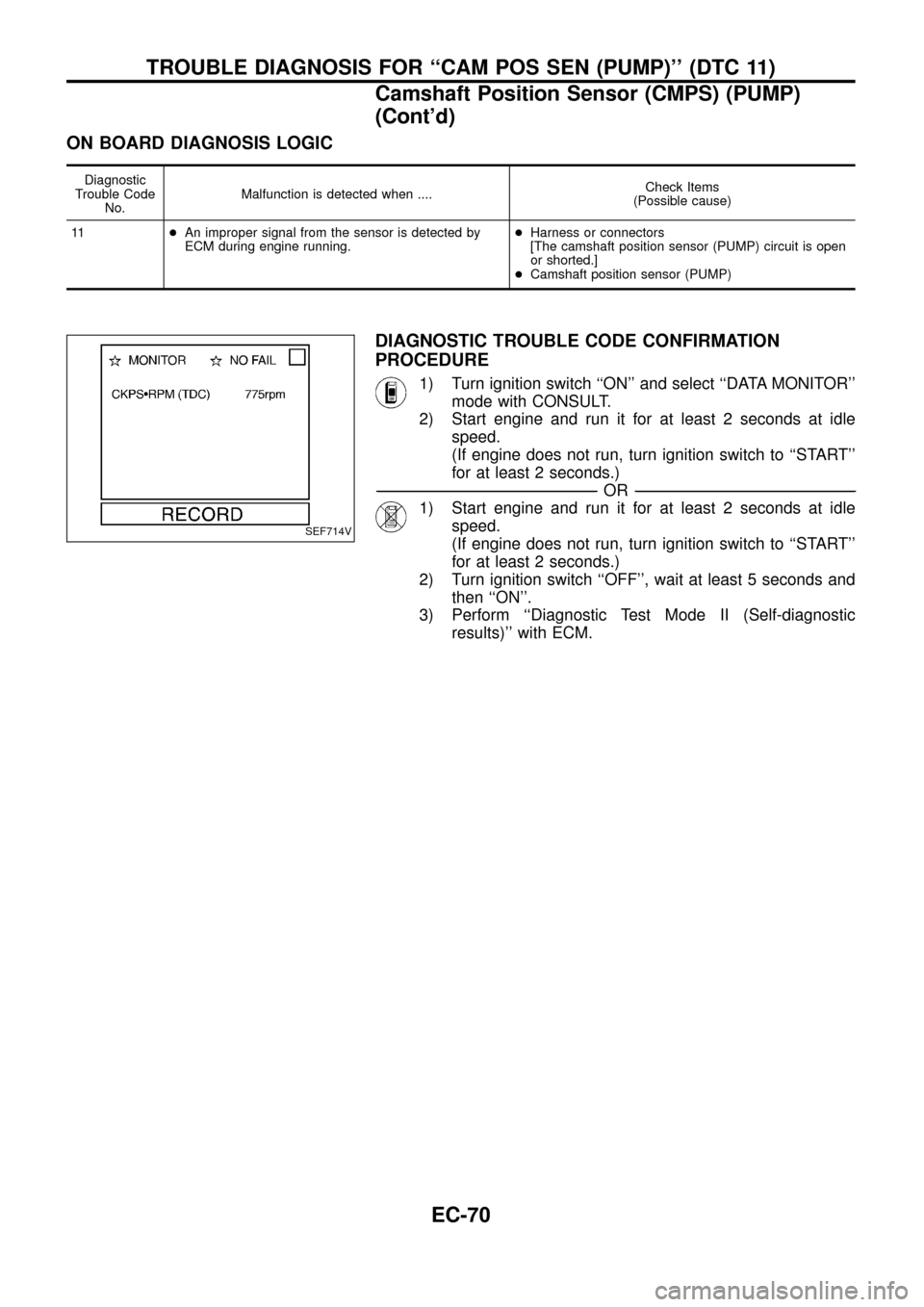
DIAGNOSTIC TROUBLE CODE CONFIRMATION
PROCEDURE
1) Turn ignition switch ``ON'' and select ``DATA MONITOR''
mode with CONSULT.
2) Start engine and run it for at least 2 seconds at idle
speed.
(If engine does not run, turn ignition switch to ``START''
for at least 2 seconds.)
-------------------------------------------------------------------------------------------------------------------------------------------------------------------------------------------------------------------------------------------------------OR-------------------------------------------------------------------------------------------------------------------------------------------------------------------------------------------------------------------------------------------------------
1) Start engine and run it for at least 2 seconds at idle
speed.
(If engine does not run, turn ignition switch to ``START''
for at least 2 seconds.)
2) Turn ignition switch ``OFF'', wait at least 5 seconds and
then ``ON''.
3) Perform ``Diagnostic Test Mode II (Self-diagnostic
results)'' with ECM.
SEF714V
TROUBLE DIAGNOSIS FOR ``CAM POS SEN (PUMP)'' (DTC 11)
Camshaft Position Sensor (CMPS) (PUMP)
(Cont'd)
EC-70
Page 73 of 192
TEC423
TROUBLE DIAGNOSIS FOR ``CAM POS SEN (PUMP)'' (DTC 11)
Camshaft Position Sensor (CMPS) (PUMP)
(Cont'd)
EC-71