NISSAN PICK-UP 1998 Repair Manual
PICK-UP 1998
NISSAN
NISSAN
https://www.carmanualsonline.info/img/5/57374/w960_57374-0.png
NISSAN PICK-UP 1998 Repair Manual
Trending: radio controls, fuse chart, four wheel drive, engine coolant, horn wire, check oil, automatic transmission fluid
Page 1031 of 1659
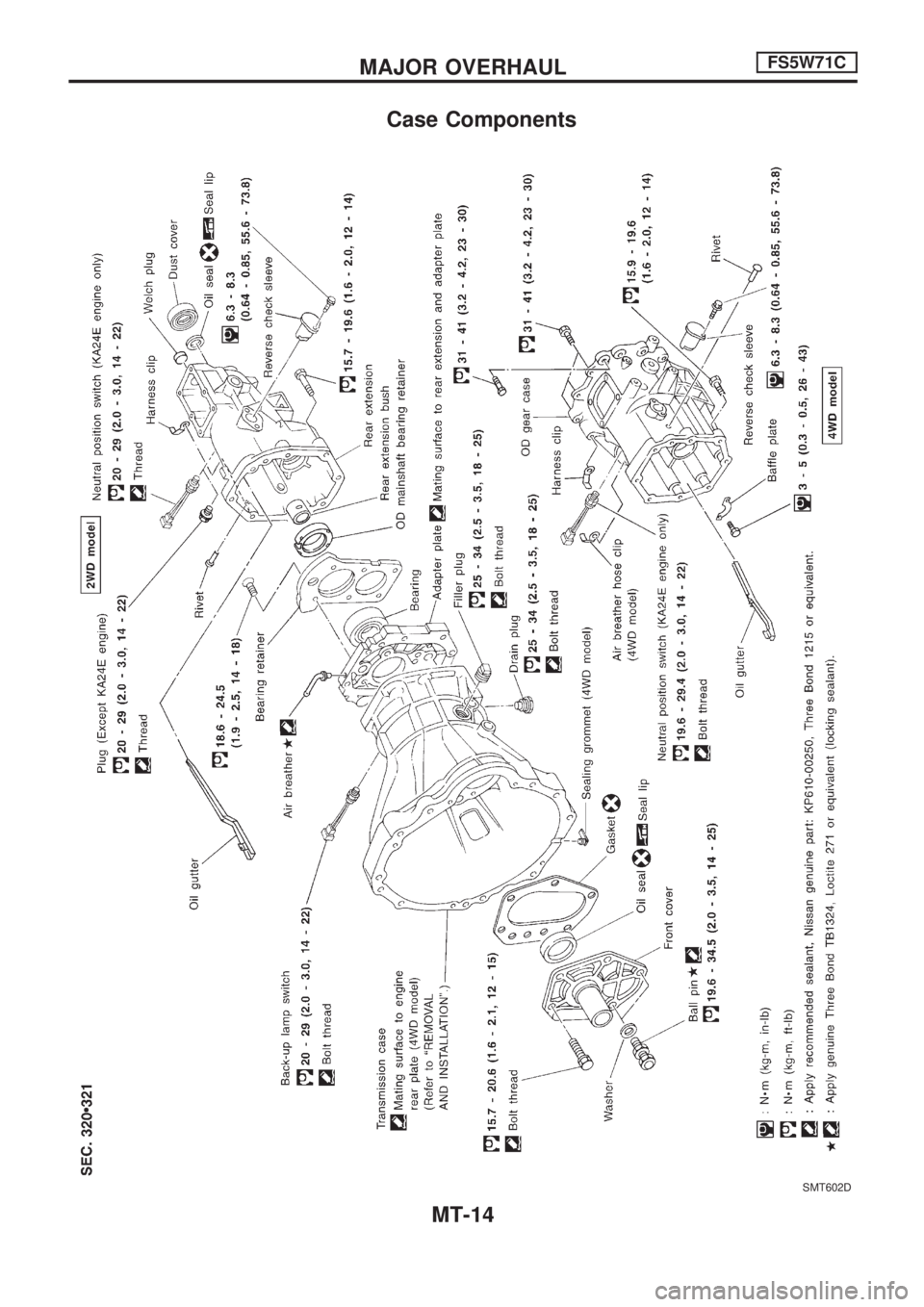
Case Components
SMT602D
MAJOR OVERHAULFS5W71C
MT-14
Page 1032 of 1659
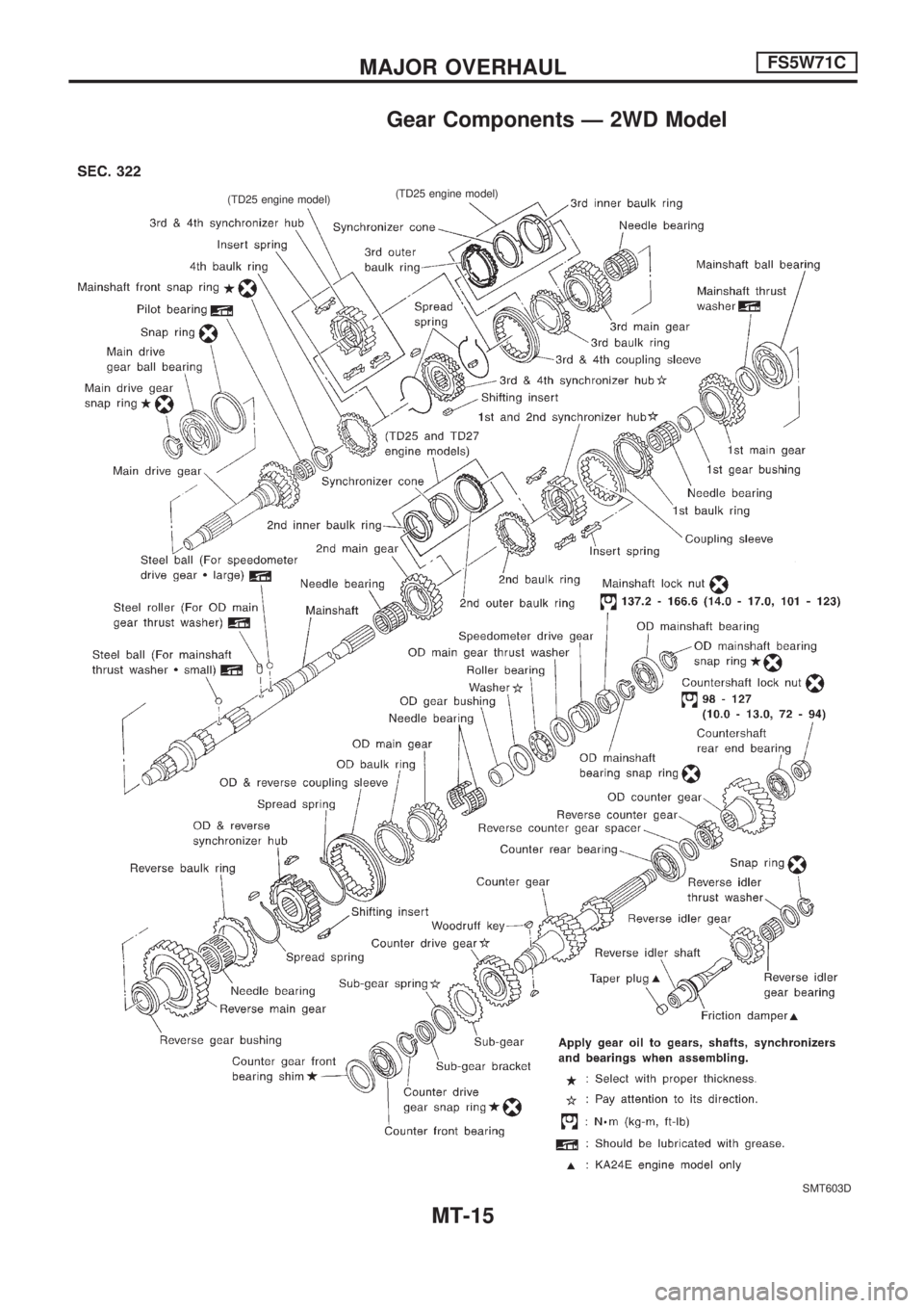
Gear Components Ð 2WD Model
SMT603D
.
(TD25 engine model)
.
(TD25 engine model)
MAJOR OVERHAULFS5W71C
MT-15
Page 1033 of 1659
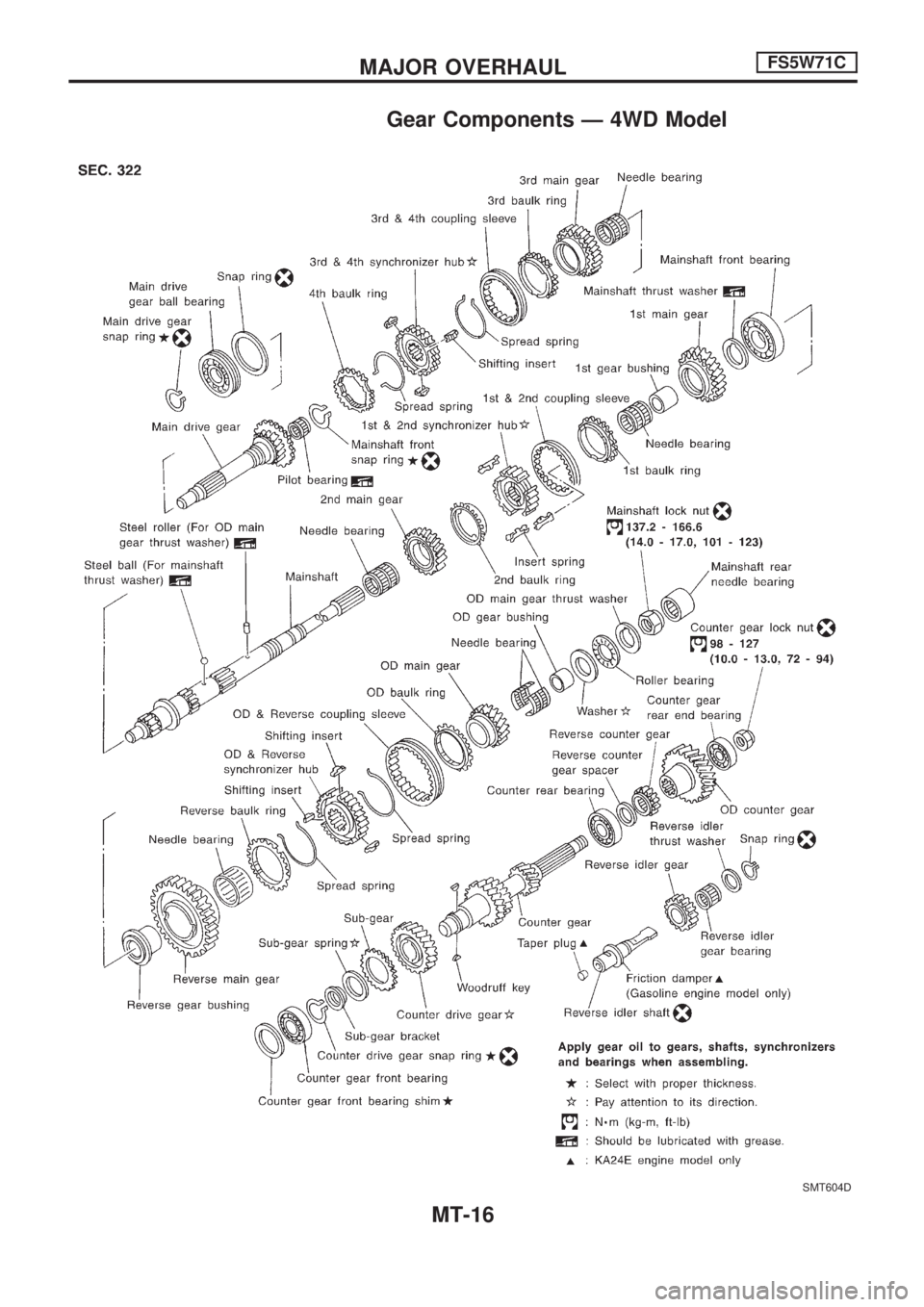
Gear Components Ð 4WD Model
SMT604D
MAJOR OVERHAULFS5W71C
MT-16
Page 1034 of 1659
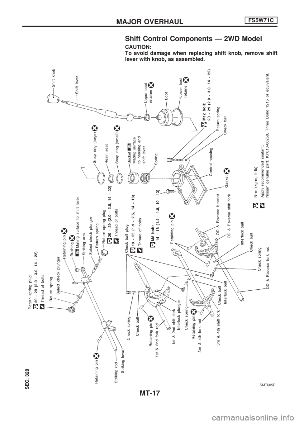
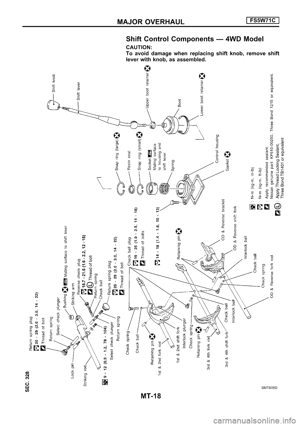
Shift Control Components Ð 2WD Model
CAUTION:
To avoid damage when replacing shift knob, remove shift
lever with knob, as assembled.
SMT605D
MAJOR OVERHAULFS5W71C
MT-17
Page 1035 of 1659
Page 1036 of 1659
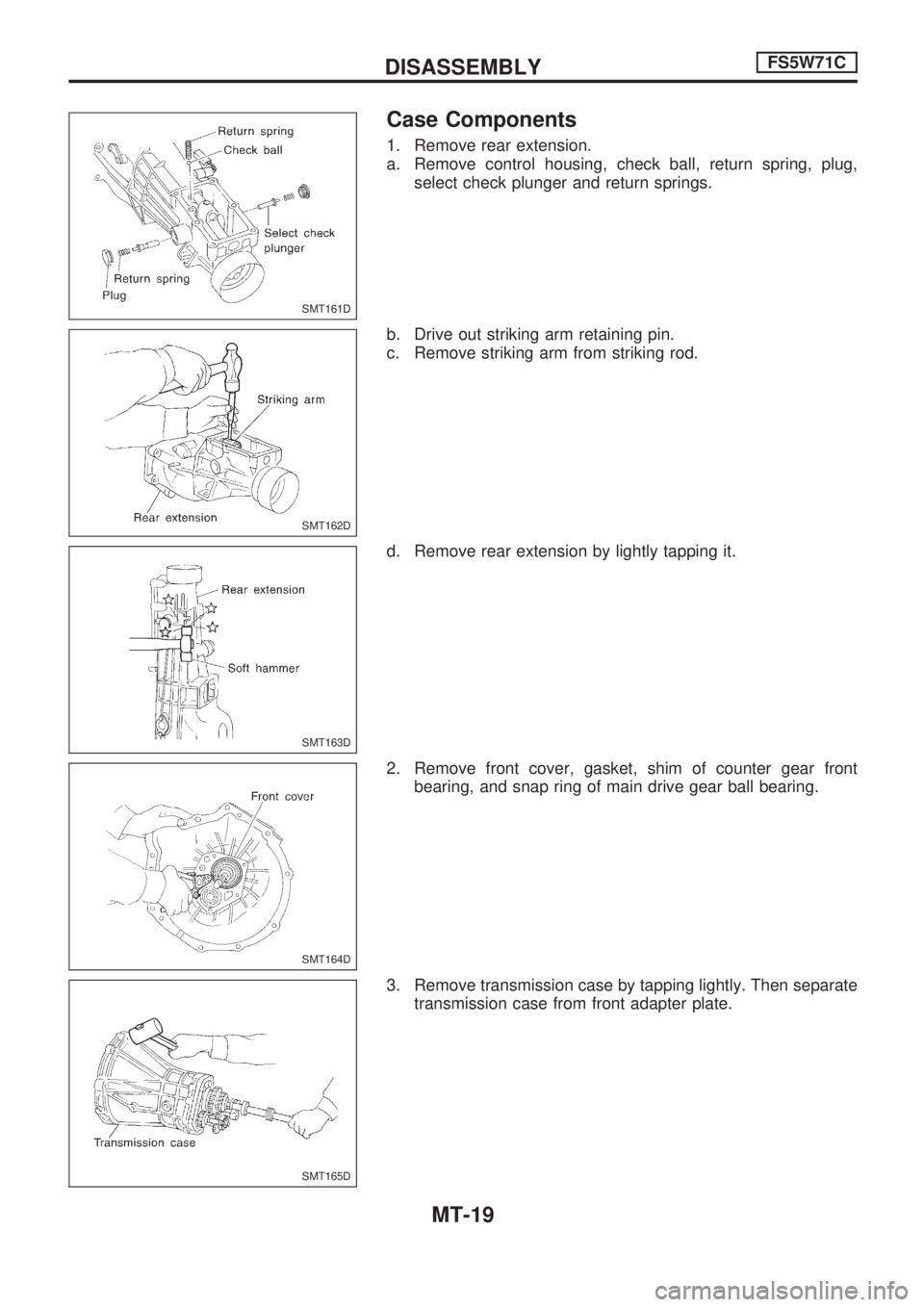
Case Components
1. Remove rear extension.
a. Remove control housing, check ball, return spring, plug,
select check plunger and return springs.
b. Drive out striking arm retaining pin.
c. Remove striking arm from striking rod.
d. Remove rear extension by lightly tapping it.
2. Remove front cover, gasket, shim of counter gear front
bearing, and snap ring of main drive gear ball bearing.
3. Remove transmission case by tapping lightly. Then separate
transmission case from front adapter plate.
SMT161D
SMT162D
SMT163D
SMT164D
SMT165D
DISASSEMBLYFS5W71C
MT-19
Page 1037 of 1659
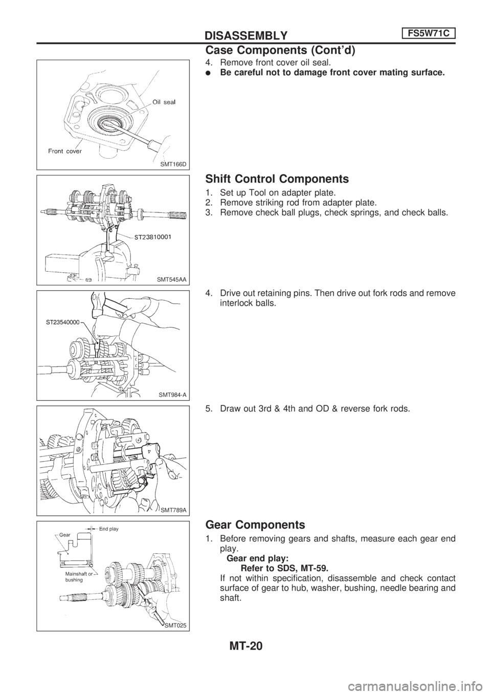
4. Remove front cover oil seal.
lBe careful not to damage front cover mating surface.
Shift Control Components
1. Set up Tool on adapter plate.
2. Remove striking rod from adapter plate.
3. Remove check ball plugs, check springs, and check balls.
4. Drive out retaining pins. Then drive out fork rods and remove
interlock balls.
5. Draw out 3rd & 4th and OD & reverse fork rods.
Gear Components
1. Before removing gears and shafts, measure each gear end
play.
Gear end play:
Refer to SDS, MT-59.
If not within specification, disassemble and check contact
surface of gear to hub, washer, bushing, needle bearing and
shaft.
SMT166D
SMT545AA
SMT984-A
SMT789A
SMT025
DISASSEMBLYFS5W71C
Case Components (Cont'd)
MT-20
Page 1038 of 1659
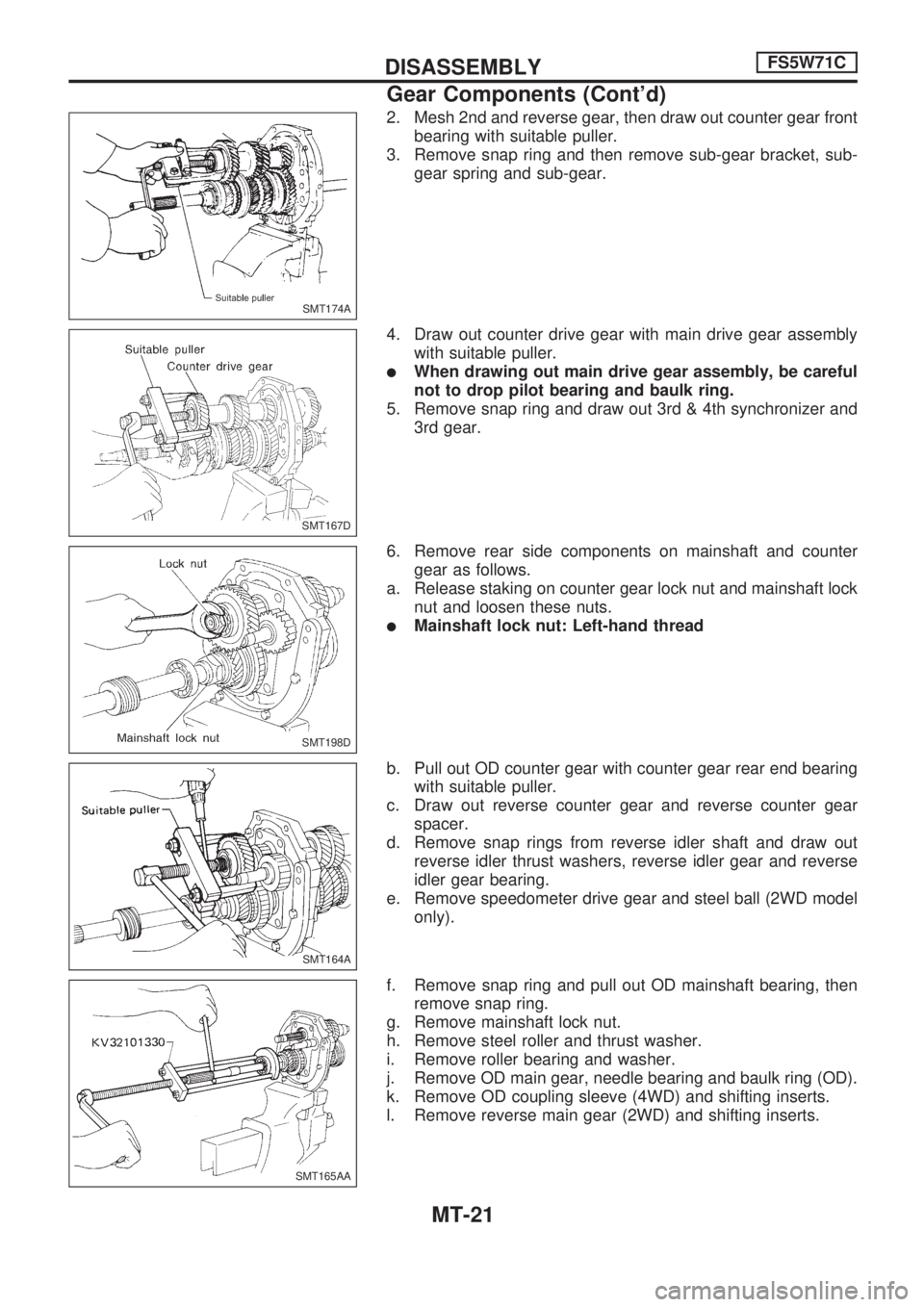
2. Mesh 2nd and reverse gear, then draw out counter gear front
bearing with suitable puller.
3. Remove snap ring and then remove sub-gear bracket, sub-
gear spring and sub-gear.
4. Draw out counter drive gear with main drive gear assembly
with suitable puller.
lWhen drawing out main drive gear assembly, be careful
not to drop pilot bearing and baulk ring.
5. Remove snap ring and draw out 3rd & 4th synchronizer and
3rd gear.
6. Remove rear side components on mainshaft and counter
gear as follows.
a. Release staking on counter gear lock nut and mainshaft lock
nut and loosen these nuts.
lMainshaft lock nut: Left-hand thread
b. Pull out OD counter gear with counter gear rear end bearing
with suitable puller.
c. Draw out reverse counter gear and reverse counter gear
spacer.
d. Remove snap rings from reverse idler shaft and draw out
reverse idler thrust washers, reverse idler gear and reverse
idler gear bearing.
e. Remove speedometer drive gear and steel ball (2WD model
only).
f. Remove snap ring and pull out OD mainshaft bearing, then
remove snap ring.
g. Remove mainshaft lock nut.
h. Remove steel roller and thrust washer.
i. Remove roller bearing and washer.
j. Remove OD main gear, needle bearing and baulk ring (OD).
k. Remove OD coupling sleeve (4WD) and shifting inserts.
l. Remove reverse main gear (2WD) and shifting inserts.
SMT174A
SMT167D
SMT198D
SMT164A
SMT165AA
DISASSEMBLYFS5W71C
Gear Components (Cont'd)
MT-21
Page 1039 of 1659
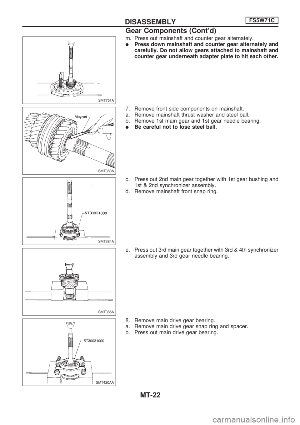
m. Press out mainshaft and counter gear alternately.
lPress down mainshaft and counter gear alternately and
carefully. Do not allow gears attached to mainshaft and
counter gear underneath adapter plate to hit each other.
7. Remove front side components on mainshaft.
a. Remove mainshaft thrust washer and steel ball.
b. Remove 1st main gear and 1st gear needle bearing.
lBe careful not to lose steel ball.
c. Press out 2nd main gear together with 1st gear bushing and
1st & 2nd synchronizer assembly.
d. Remove mainshaft front snap ring.
e. Press out 3rd main gear together with 3rd & 4th synchronizer
assembly and 3rd gear needle bearing.
8. Remove main drive gear bearing.
a. Remove main drive gear snap ring and spacer.
b. Press out main drive gear bearing.
SMT751A
SMT383A
SMT384A
SMT385A
SMT420AA
DISASSEMBLYFS5W71C
Gear Components (Cont'd)
MT-22
Page 1040 of 1659
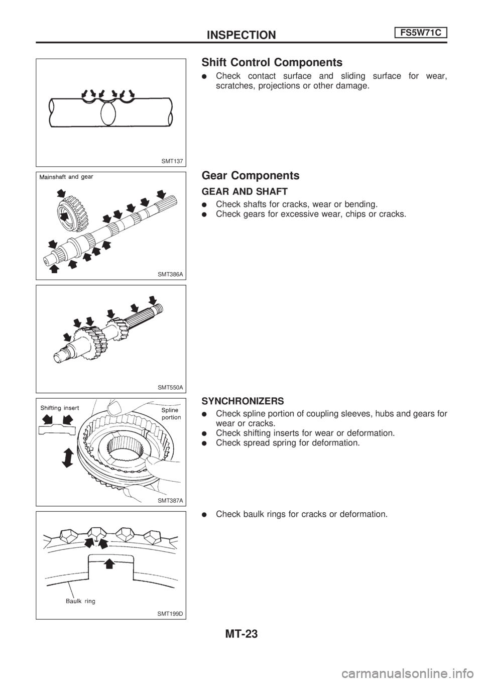
Shift Control Components
lCheck contact surface and sliding surface for wear,
scratches, projections or other damage.
Gear Components
GEAR AND SHAFT
lCheck shafts for cracks, wear or bending.
lCheck gears for excessive wear, chips or cracks.
SYNCHRONIZERS
lCheck spline portion of coupling sleeves, hubs and gears for
wear or cracks.
lCheck shifting inserts for wear or deformation.
lCheck spread spring for deformation.
lCheck baulk rings for cracks or deformation.
SMT137
SMT386A
SMT550A
SMT387A
SMT199D
INSPECTIONFS5W71C
MT-23
Trending: spark plugs replace, remove seats, wheel size, fuel type, engine, sensor, change time
