NISSAN PRIMERA 1999 Electronic Repair Manual
Manufacturer: NISSAN, Model Year: 1999, Model line: PRIMERA, Model: NISSAN PRIMERA 1999Pages: 2267, PDF Size: 35.74 MB
Page 751 of 2267

Wiring DiagramNCEC0352
YEC072A
DTC P1402 EGR FUNCTION (OPEN) (IF SO EQUIPPED)QG16I18DE
Wiring Diagram
EC-309
Page 752 of 2267
Diagnostic ProcedureNCEC0353
1 CHECK POWER SUPPLY
1. Disconnect EGR volume control valve harness connector.
2. Turn ignition switch ªONº.
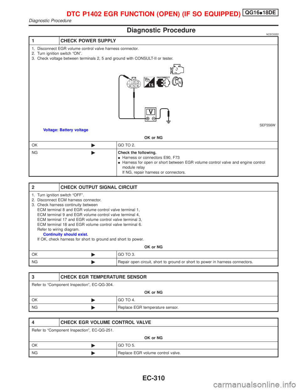
3. Check voltage between terminals 2, 5 and ground with CONSULT-II or tester.
SEF556WVoltage: Battery voltage
OK or NG
OK©GO TO 2.
NG©Check the following.
IHarness or connectors E90, F73
IHarness for open or short between EGR volume control valve and engine control
module relay
If NG, repair harness or connectors.
2 CHECK OUTPUT SIGNAL CIRCUIT
1. Turn ignition switch ªOFFº.
2. Disconnect ECM harness connector.
3. Check harness continuity between
ECM terminal 8 and EGR volume control valve terminal 1,
ECM terminal 9 and EGR volume control valve terminal 4,
ECM terminal 17 and EGR volume control valve terminal 3,
ECM terminal 18 and EGR volume control valve terminal 6.
Refer to wiring diagram.
Continuity should exist.
If OK, check harness for short to ground and short to power.
OK or NG
OK©GO TO 3.
NG©Repair open circuit, short to ground or short to power in harness connectors.
3 CHECK EGR TEMPERATURE SENSOR
Refer to ªComponent Inspectionº, EC-QG-304.
OK or NG
OK©GO TO 4.
NG©Replace EGR temperature sensor.
4 CHECK EGR VOLUME CONTROL VALVE
Refer to ªComponent Inspectionº, EC-QG-251.
OK or NG
OK©GO TO 5.
NG©Replace EGR volume control valve.
DTC P1402 EGR FUNCTION (OPEN) (IF SO EQUIPPED)QG16I18DE
Diagnostic Procedure
EC-310
Page 753 of 2267
5 CHECK INTERMITTENT INCIDENT
Perform ªTROUBLE DIAGNOSIS FOR INTERMITTENT INCIDENTº, EC-QG-102.
©INSPECTION END
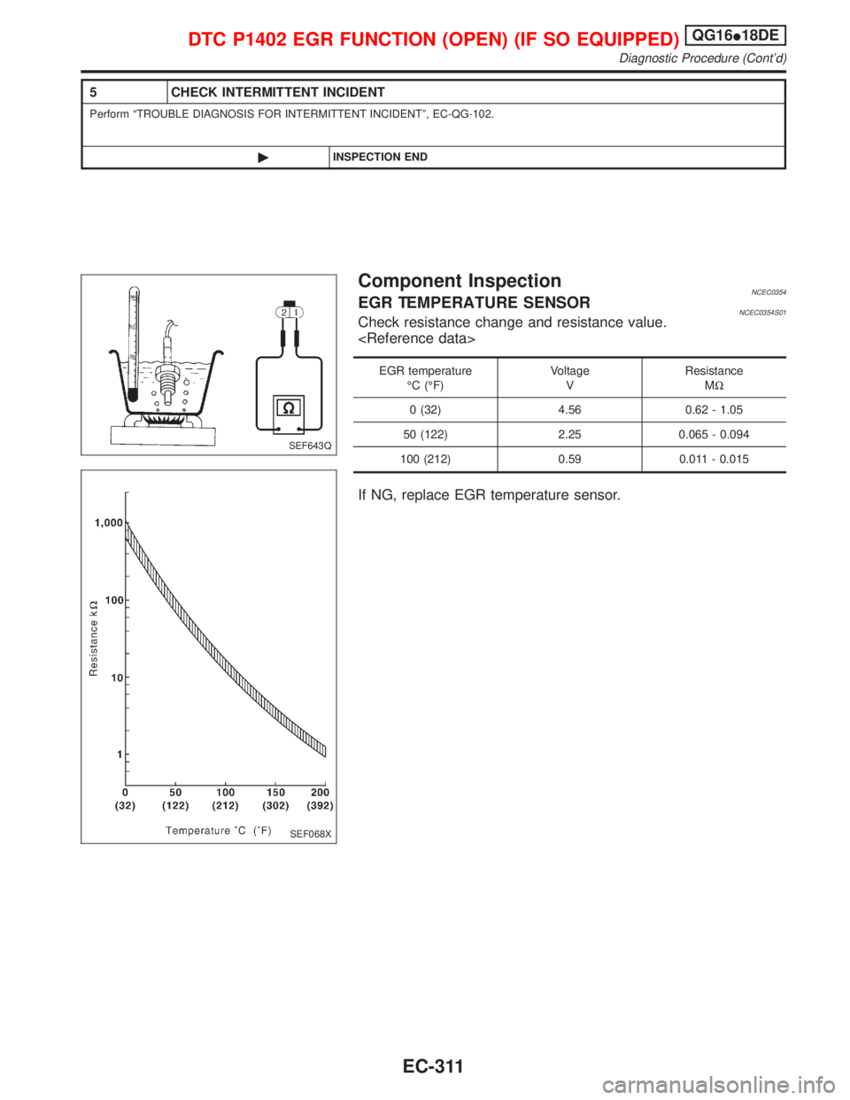
Component InspectionNCEC0354EGR TEMPERATURE SENSORNCEC0354S01Check resistance change and resistance value.
EGR temperature
ÉC (ÉF)Voltage
VResistance
MW
0 (32) 4.56 0.62 - 1.05
50 (122) 2.25 0.065 - 0.094
100 (212) 0.59 0.011 - 0.015
If NG, replace EGR temperature sensor.
SEF643Q
SEF068X
DTC P1402 EGR FUNCTION (OPEN) (IF SO EQUIPPED)QG16I18DE
Diagnostic Procedure (Cont'd)
EC-311
Page 754 of 2267
EGR VOLUME CONTROL VALVENCEC0354S04With CONSULT-II
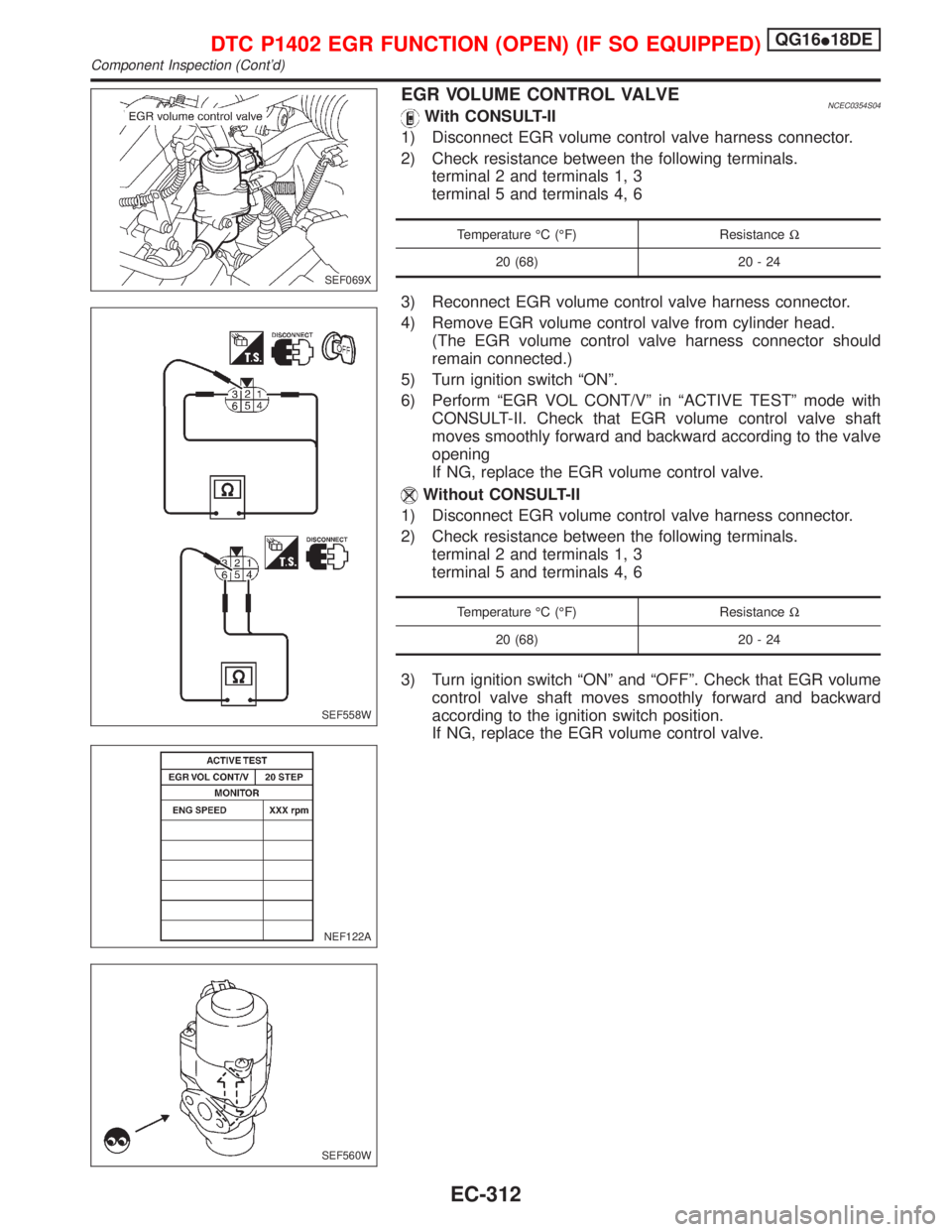
1) Disconnect EGR volume control valve harness connector.
2) Check resistance between the following terminals.
terminal 2 and terminals 1, 3
terminal 5 and terminals 4, 6
Temperature ÉC (ÉF) ResistanceW
20 (68) 20 - 24
3) Reconnect EGR volume control valve harness connector.
4) Remove EGR volume control valve from cylinder head.
(The EGR volume control valve harness connector should
remain connected.)
5) Turn ignition switch ªONº.
6) Perform ªEGR VOL CONT/Vº in ªACTIVE TESTº mode with
CONSULT-II. Check that EGR volume control valve shaft
moves smoothly forward and backward according to the valve
opening
If NG, replace the EGR volume control valve.
Without CONSULT-II
1) Disconnect EGR volume control valve harness connector.
2) Check resistance between the following terminals.
terminal 2 and terminals 1, 3
terminal 5 and terminals 4, 6
Temperature ÉC (ÉF) ResistanceW
20 (68) 20 - 24
3) Turn ignition switch ªONº and ªOFFº. Check that EGR volume
control valve shaft moves smoothly forward and backward
according to the ignition switch position.
If NG, replace the EGR volume control valve.
SEF069X
SEF558W
NEF122A
SEF560W
DTC P1402 EGR FUNCTION (OPEN) (IF SO EQUIPPED)QG16I18DE
Component Inspection (Cont'd)
EC-312
Page 755 of 2267
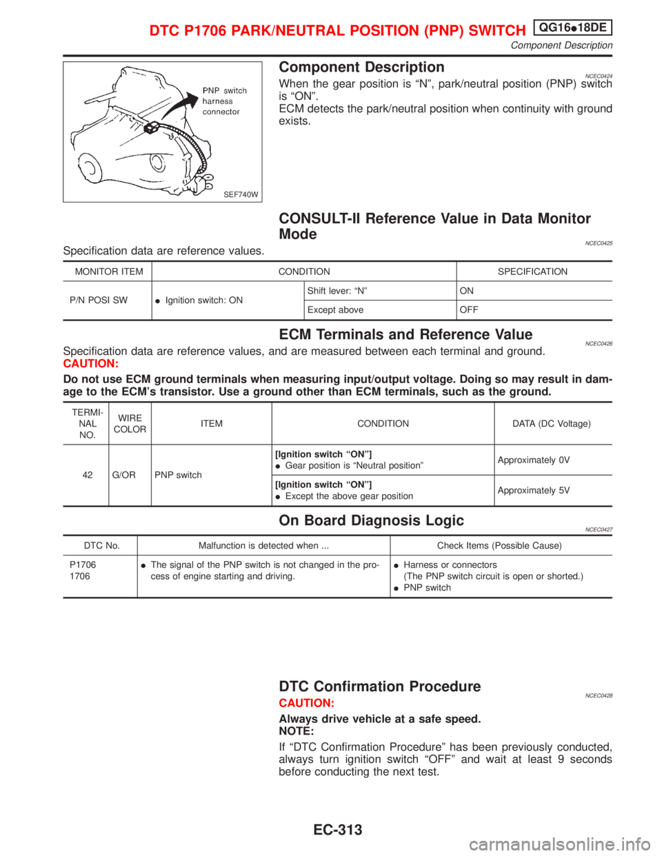
Component DescriptionNCEC0424When the gear position is ªNº, park/neutral position (PNP) switch
is ªONº.
ECM detects the park/neutral position when continuity with ground
exists.
CONSULT-II Reference Value in Data Monitor
Mode
NCEC0425Specification data are reference values.
MONITOR ITEM CONDITION SPECIFICATION
P/N POSI SWIIgnition switch: ONShift lever: ªNº ON
Except above OFF
ECM Terminals and Reference ValueNCEC0426Specification data are reference values, and are measured between each terminal and ground.
CAUTION:
Do not use ECM ground terminals when measuring input/output voltage. Doing so may result in dam-
age to the ECM's transistor. Use a ground other than ECM terminals, such as the ground.
TERMI-
NAL
NO.WIRE
COLORITEM CONDITION DATA (DC Voltage)
42 G/OR PNP switch[Ignition switch ªONº]
IGear position is ªNeutral positionºApproximately 0V
[Ignition switch ªONº]
IExcept the above gear positionApproximately 5V
On Board Diagnosis LogicNCEC0427
DTC No. Malfunction is detected when ... Check Items (Possible Cause)
P1706
1706IThe signal of the PNP switch is not changed in the pro-
cess of engine starting and driving.IHarness or connectors
(The PNP switch circuit is open or shorted.)
IPNP switch
DTC Confirmation ProcedureNCEC0428CAUTION:
Always drive vehicle at a safe speed.
NOTE:
If ªDTC Confirmation Procedureº has been previously conducted,
always turn ignition switch ªOFFº and wait at least 9 seconds
before conducting the next test.
SEF740W
DTC P1706 PARK/NEUTRAL POSITION (PNP) SWITCHQG16I18DE
Component Description
EC-313
Page 756 of 2267
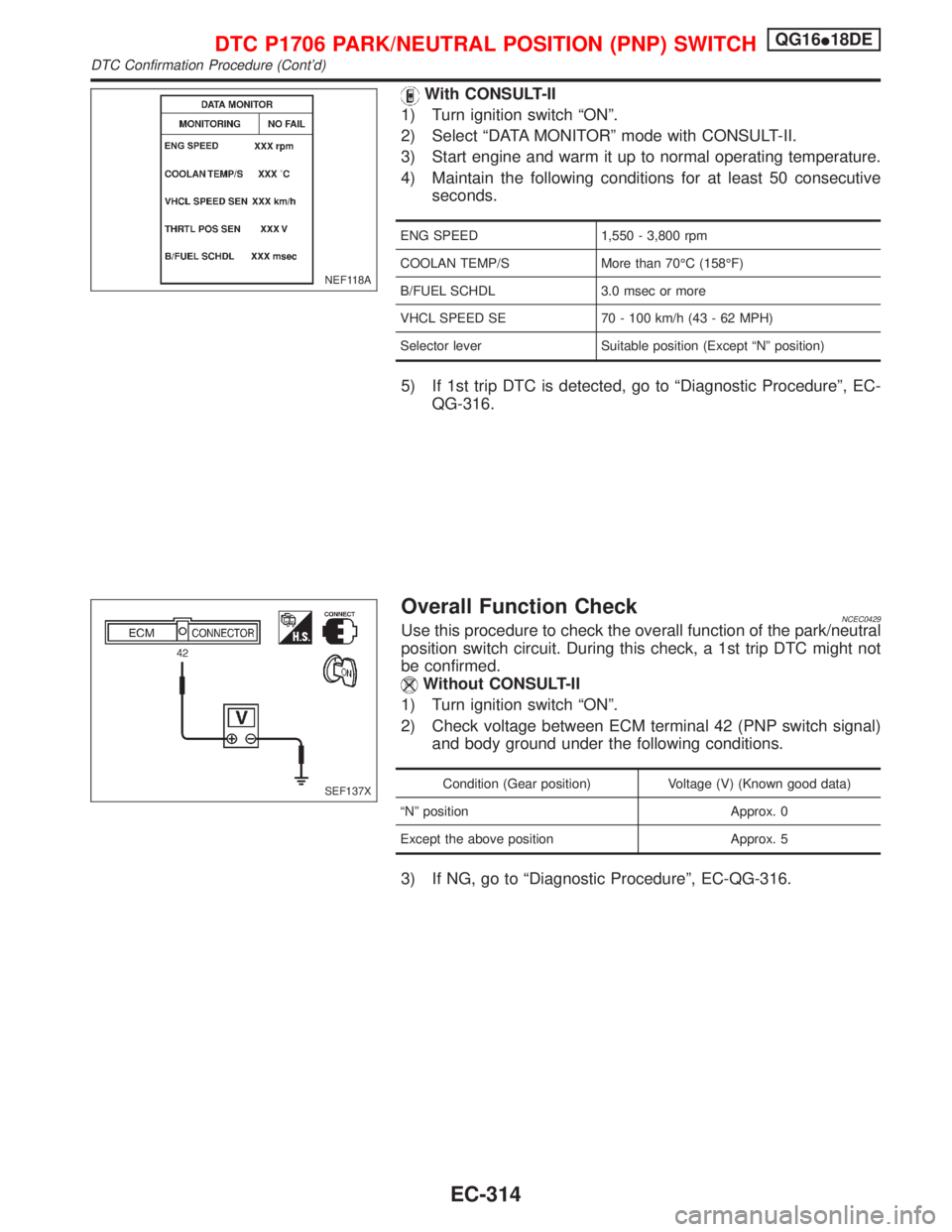
With CONSULT-II
1) Turn ignition switch ªONº.
2) Select ªDATA MONITORº mode with CONSULT-II.
3) Start engine and warm it up to normal operating temperature.
4) Maintain the following conditions for at least 50 consecutive
seconds.
ENG SPEED 1,550 - 3,800 rpm
COOLAN TEMP/S More than 70ÉC (158ÉF)
B/FUEL SCHDL 3.0 msec or more
VHCL SPEED SE 70 - 100 km/h (43 - 62 MPH)
Selector lever Suitable position (Except ªNº position)
5) If 1st trip DTC is detected, go to ªDiagnostic Procedureº, EC-
QG-316.
Overall Function CheckNCEC0429Use this procedure to check the overall function of the park/neutral
position switch circuit. During this check, a 1st trip DTC might not
be confirmed.
Without CONSULT-II
1) Turn ignition switch ªONº.
2) Check voltage between ECM terminal 42 (PNP switch signal)
and body ground under the following conditions.
Condition (Gear position) Voltage (V) (Known good data)
ªNº position Approx. 0
Except the above position Approx. 5
3) If NG, go to ªDiagnostic Procedureº, EC-QG-316.
NEF118A
SEF137X
DTC P1706 PARK/NEUTRAL POSITION (PNP) SWITCHQG16I18DE
DTC Confirmation Procedure (Cont'd)
EC-314
Page 757 of 2267
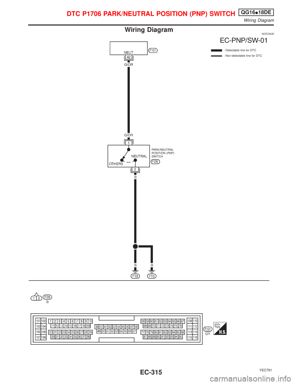
Wiring DiagramNCEC0430
YEC791
: Detectable line for DTC
: Non-detectable line for DTC
PARK/NEUTRAL
POSITION (PNP)
SWITCH
DTC P1706 PARK/NEUTRAL POSITION (PNP) SWITCHQG16I18DE
Wiring Diagram
EC-315
Page 758 of 2267
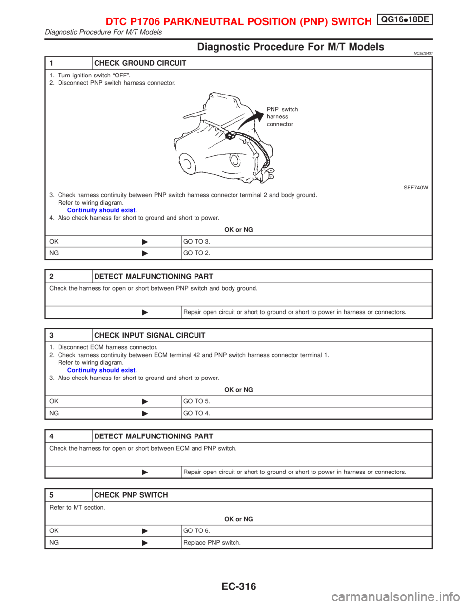
Diagnostic Procedure For M/T ModelsNCEC0431
1 CHECK GROUND CIRCUIT
1. Turn ignition switch ªOFFº.
2. Disconnect PNP switch harness connector.
SEF740W3. Check harness continuity between PNP switch harness connector terminal 2 and body ground.
Refer to wiring diagram.
Continuity should exist.
4. Also check harness for short to ground and short to power.
OK or NG
OK©GO TO 3.
NG©GO TO 2.
2 DETECT MALFUNCTIONING PART
Check the harness for open or short between PNP switch and body ground.
©Repair open circuit or short to ground or short to power in harness or connectors.
3 CHECK INPUT SIGNAL CIRCUIT
1. Disconnect ECM harness connector.
2. Check harness continuity between ECM terminal 42 and PNP switch harness connector terminal 1.
Refer to wiring diagram.
Continuity should exist.
3. Also check harness for short to ground and short to power.
OK or NG
OK©GO TO 5.
NG©GO TO 4.
4 DETECT MALFUNCTIONING PART
Check the harness for open or short between ECM and PNP switch.
©Repair open circuit or short to ground or short to power in harness or connectors.
5 CHECK PNP SWITCH
Refer to MT section.
OK or NG
OK©GO TO 6.
NG©Replace PNP switch.
DTC P1706 PARK/NEUTRAL POSITION (PNP) SWITCHQG16I18DE
Diagnostic Procedure For M/T Models
EC-316
Page 759 of 2267

6 CHECK INTERMITTENT INCIDENT
Perform ªTROUBLE DIAGNOSIS FOR INTERMITTENT INCIDENTº, EC-QG-102.
©INSPECTION END
DTC P1706 PARK/NEUTRAL POSITION (PNP) SWITCHQG16I18DE
Diagnostic Procedure For M/T Models (Cont'd)
EC-317
Page 760 of 2267
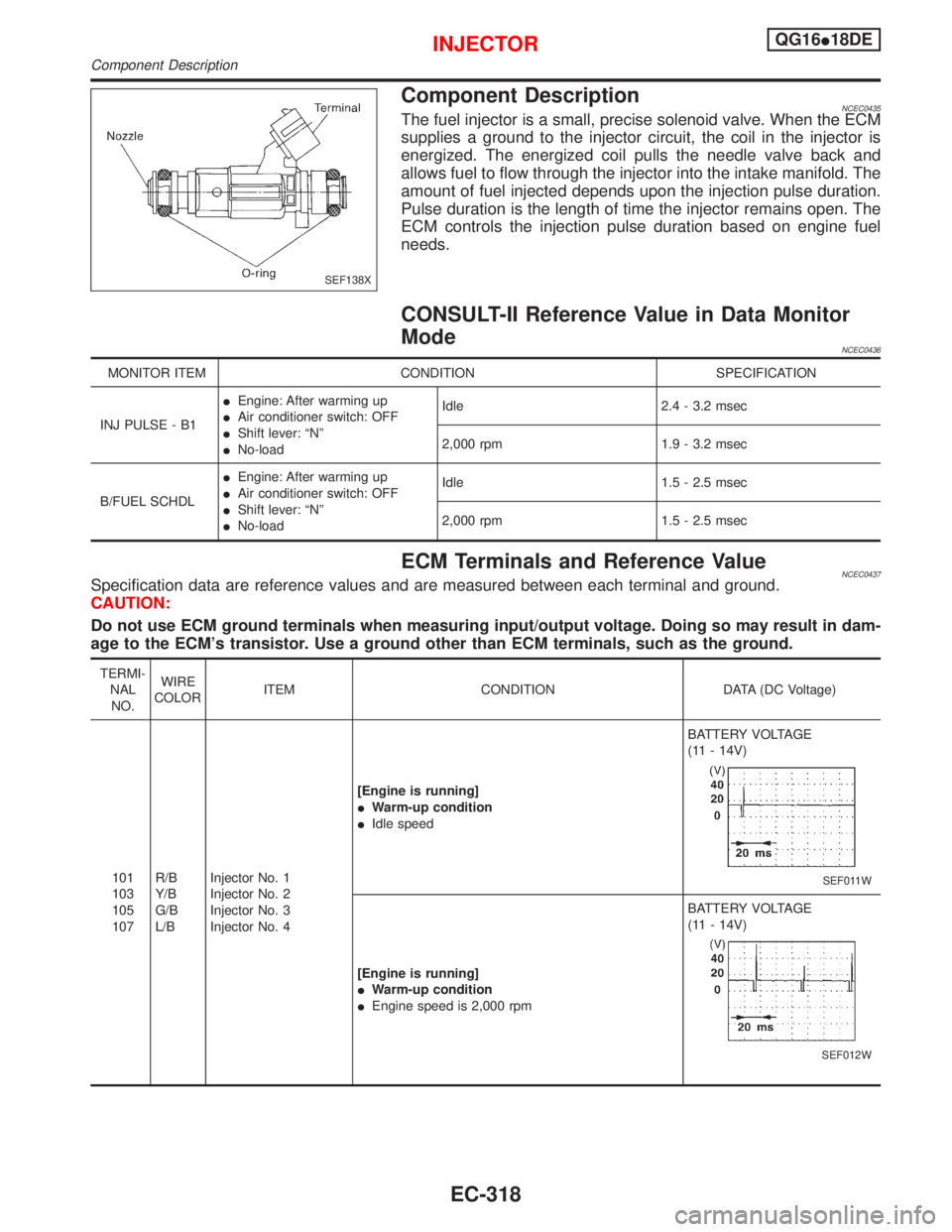
Component DescriptionNCEC0435The fuel injector is a small, precise solenoid valve. When the ECM
supplies a ground to the injector circuit, the coil in the injector is
energized. The energized coil pulls the needle valve back and
allows fuel to flow through the injector into the intake manifold. The
amount of fuel injected depends upon the injection pulse duration.
Pulse duration is the length of time the injector remains open. The
ECM controls the injection pulse duration based on engine fuel
needs.
CONSULT-II Reference Value in Data Monitor
Mode
NCEC0436
MONITOR ITEM CONDITION SPECIFICATION
INJ PULSE - B1IEngine: After warming up
IAir conditioner switch: OFF
IShift lever: ªNº
INo-loadIdle 2.4 - 3.2 msec
2,000 rpm 1.9 - 3.2 msec
B/FUEL SCHDLIEngine: After warming up
IAir conditioner switch: OFF
IShift lever: ªNº
INo-loadIdle 1.5 - 2.5 msec
2,000 rpm 1.5 - 2.5 msec
ECM Terminals and Reference ValueNCEC0437Specification data are reference values and are measured between each terminal and ground.
CAUTION:
Do not use ECM ground terminals when measuring input/output voltage. Doing so may result in dam-
age to the ECM's transistor. Use a ground other than ECM terminals, such as the ground.
TERMI-
NAL
NO.WIRE
COLORITEM CONDITION DATA (DC Voltage)
101
103
105
107R/B
Y/B
G/B
L/BInjector No. 1
Injector No. 2
Injector No. 3
Injector No. 4[Engine is running]
IWarm-up condition
IIdle speedBATTERY VOLTAGE
(11 - 14V)
SEF011W
[Engine is running]
IWarm-up condition
IEngine speed is 2,000 rpmBATTERY VOLTAGE
(11 - 14V)
SEF012W
SEF138X
INJECTORQG16I18DE
Component Description
EC-318