Engine warning NISSAN QASHQAI 2012 Service Manual
[x] Cancel search | Manufacturer: NISSAN, Model Year: 2012, Model line: QASHQAI, Model: NISSAN QASHQAI 2012Pages: 297, PDF Size: 4.09 MB
Page 64 of 297
![NISSAN QASHQAI 2012 Service Manual Downloaded from www.Manualslib.com manuals search engine However reset is possible (only after the oil was
changed) using the [Service] menu item in the
[Settings] menu. See “[Maintenance]” later NISSAN QASHQAI 2012 Service Manual Downloaded from www.Manualslib.com manuals search engine However reset is possible (only after the oil was
changed) using the [Service] menu item in the
[Settings] menu. See “[Maintenance]” later](/img/5/56764/w960_56764-63.png)
Downloaded from www.Manualslib.com manuals search engine However reset is possible (only after the oil was
changed) using the [Service] menu item in the
[Settings] menu. See “[Maintenance]” later in this
section
Have the vehicle inspected by a NISSAN dealer
or qualified workshop if these conditions occur.
j20Distance to maintenance alert
(where fitted)
This alert reminds when maintenance is due in the
shown distance. The alert is shown for 10 seconds
at ignition ON, when the distance to the next main-
tenance interval is below 5000 km (3100 Miles).
The message is shown until the steering wheel
switch
ji (where fitted) is pressed.
NOTE
Visit a NISSAN dealer or qualified workshop
before the maintenance due alertj19reaches
0 km (miles) to perform maintenance (oil
change).
The maintenance interval will reduce faster
with certain types of driving, especially at low
speeds in urban conditions.
j21Tyre change alert
You can set a distance for changing tyres. See
“[Maintenance]” later in this section
j22Maintenance alert
You can set a distance for a non specific mainte-
nance item. See “[Maintenance]” later in this sec-
tion
j23Low temperature warning
If, during driving, the temperature falls below 4ºC
this alert will appear to indicate low outside air tem-
perature. You can switch the low temperature warn-
ing [On] or [Off]. See “[Units]” later in this section
CAUTION
Even if the alert is not on, there is no guarantee
that the road is free of hazards caused by in-
clement weather.
NOTE
The outside air temperature sensor is located at
the front of the vehicle. At low speeds the sensor
can be affected by engine heat, heat reflected
from the road surface and exhaust from other
vehicles, these influences can cause the display
to be inaccurate. To compensate, the outside air
temperature display is designed to react slowly
to increasing temperatures, but quickly to falling
temperatures.
j24Low fuel warning
This warning appears when the fuel level in the tank
is getting low. Refuel as soon as it is convenient,
preferably before the fuel gauge reaches the empty
position. For more information, see “Fuel gauge”
earlier in this section.
j25Driver alert
This warning appears when the previously set time
for a break is reached. You can set the time for up
to 6 hours in the setting menu. (See “Settings menu”
later in this section.)
Stop/Start System (where fitted)
For more information, see “Stop/Start System
(where fitted)” in the “5. Starting and driving” sec-
tion
j26Engine stop:
If the engine stops when the Stop/Start System is
activated, the message is shown.
j27Auto start deactivation:
If the engine stops when the Stop/Start System is
activated, and will not start automatically, the mes-
sage is shown.
j28System fault:
If the Stop/Start System is activated, but does not
operate correctly, the message is shown. Visit a
NISSAN dealer or qualified workshop.
Activating or deactivating using the Stop/Start
System OFF switch:
Using the Stop/Start System OFF switch activates
or deactivates the Stop/Start System. This is shown
in the vehicle information display:
j29 :The Stop/Start System OFF switch is
pushed to the “ON” position.
j30 :The Stop/Start System OFF switch is pushed to
the “OFF” position.
Instruments and controls2-15
Page 70 of 297
![NISSAN QASHQAI 2012 Service Manual Downloaded from www.Manualslib.com manuals search engine For more information, contact your NISSAN dealer
or qualified workshop.
[Language]
Select the submenu to set the desired language of
the displa NISSAN QASHQAI 2012 Service Manual Downloaded from www.Manualslib.com manuals search engine For more information, contact your NISSAN dealer
or qualified workshop.
[Language]
Select the submenu to set the desired language of
the displa](/img/5/56764/w960_56764-69.png)
Downloaded from www.Manualslib.com manuals search engine For more information, contact your NISSAN dealer
or qualified workshop.
[Language]
Select the submenu to set the desired language of
the display
[Factory]
Select the submenu to reset the factory settings of
the display.
NOTE
When resetting [Factory], all previous settings
made are changed to default.
CRUISE CONTROL/SPEED LIMITER
INDICATOR (where fitted)
The CRUISE indicator is displayed when the
cruise control main “ON/OFF” switch is pushed.
When the main switch is pushed again, theCRUISE indicator disappears. When the
CRUISE indicator is displayed, the cruise con-
trol system is operational.
The cruise control SET indicator is displayed
while the vehicle speed is controlled by the cruise
control system. If the SET indicator blinks while
the engine is running, it may indicate that the
cruise control system is not functioning properly.
Have the system checked by an NISSAN dealer
or qualified workshop.
For more details, see “Cruise control (where
fitted)” in the “5. Starting and driving” section.
The LIMIT indicator is displayed when the speed
limiter main “ON/OFF” switch is pushed. When
the main switch is pushed again, the LIMIT indi-
cator disappears.
When the LIMIT indicator is displayed, the speed
limiter is operational. The speed limiter is active,
when the SET indicator is displayed.
For more details, see “Speed limiter” in the
“5. Starting and driving” section.
When the trip computer was set before using the
cruise control or speed limiter function, the trip com-
puter menu item
jA is shown together with the
cruise control or speed limiter. See “Trip computer”
earlier in this section
WARNING
In freezing temperatures the washer fluid may
freeze on the windscreen and obscure your vi-
sion. Warm the windscreen with the defroster
before you wash it.
CAUTION
Do not open/release the bonnet when the
front wiper arms are raised from their original
position.
Do not operate the washer continuously for
more than 15 seconds.
Do not operate the washer if the reservoir
tank is empty or frozen.
NIC1550
WIPER AND WASHER SWITCH
Instruments and controls2-21
Page 72 of 297
Downloaded from www.Manualslib.com manuals search engine REAR WINDOW
WARNING
In freezing temperatures the washer solution
may freeze on the rear window and obscure your
vision. Warm the rear window with the rear win-
dow defogger before you wash the rear window.
CAUTION
Do not operate the washer continuously for
more than 15 seconds.
Do not operate the washer if the reservoir
tank is empty or frozen.
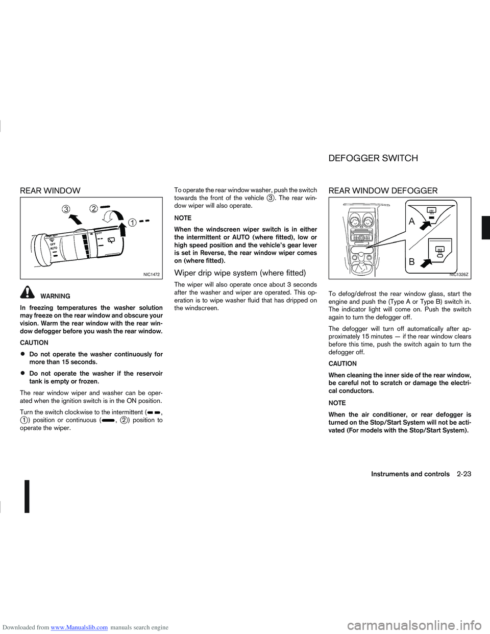
The rear window wiper and washer can be oper-
ated when the ignition switch is in the ON position.
Turn the switch clockwise to the intermittent (
,j1 ) position or continuous (,j2 ) position to
operate the wiper. To operate the rear window washer, push the switch
towards the front of the vehicle
j3 . The rear win-
dow wiper will also operate.
NOTE
When the windscreen wiper switch is in either
the intermittent or AUTO (where fitted), low or
high speed position and the vehicle’s gear lever
is set in Reverse, the rear window wiper comes
on (where fitted).
Wiper drip wipe system (where fitted)
The wiper will also operate once about 3 seconds
after the washer and wiper are operated. This op-
eration is to wipe washer fluid that has dripped on
the windscreen.
REAR WINDOW DEFOGGER
To defog/defrost the rear window glass, start the
engine and push the (Type A or Type B) switch in.
The indicator light will come on. Push the switch
again to turn the defogger off.
The defogger will turn off automatically after ap-
proximately 15 minutes — if the rear window clears
before this time, push the switch again to turn the
defogger off.
CAUTION
When cleaning the inner side of the rear window,
be careful not to scratch or damage the electri-
cal conductors.
NOTE
When the air conditioner, or rear defogger is
turned on the Stop/Start System will not be acti-
vated (For models with the Stop/Start System).
NIC1472NIC1326Z
DEFOGGER SWITCH
Instruments and controls2-23
Page 73 of 297
Downloaded from www.Manualslib.com manuals search engine OUTSIDE MIRROR DEFOGGER
(where fitted)
The outside rear-view mirrors will be defogged when
the defogger switch is activated.
XENON HEADLIGHTS (where fitted)
WARNING
HIGH VOLTAGE
When xenon headlights are on, they produce
a high voltage. To prevent an electric shock,
never attempt to modify or disassemble. Al-
ways have your xenon headlights replaced at
an authorised NISSAN dealer or qualified
workshop.
Xenon headlights provide considerably more
light than conventional headlights. If they are
not correctly aimed, they might temporarily
blind an oncoming driver or the driver ahead
of you and cause a serious accident. If head-
lights are not aimed correctly, immediately
take your vehicle to a NISSAN dealer or quali-
fied workshop and have the headlights ad-
justed correctly.
When the xenon headlight is initially turned on, its
brightness or colour varies slightly. However, the
colour and brightness will soon stabilise.
The life of xenon headlights will be shortened by
frequent on-off operation. It is generally desir-
able not to turn off the headlights for short inter-
vals (for example, when the vehicle stops at a
traffic signal).
If the xenon headlight bulb is close to burning
out, the brightness will drastically decrease, the
light will start blinking, or the colour of the light will become reddish. If one or more of the above
signs occur, contact a NISSAN dealer or quali-
fied workshop.
NISSAN recommends you to consult the local regu-
lations concerning the use of lights.
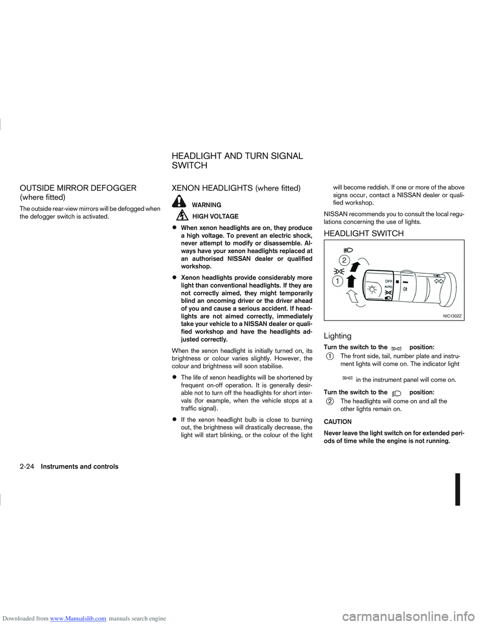
HEADLIGHT SWITCH
Lighting
Turn the switch to themposition:
j1 The front side, tail, number plate and instru- ment lights will come on. The indicator light
min the instrument panel will come on.
Turn the switch to the
mposition:
j2 The headlights will come on and all the other lights remain on.
CAUTION
Never leave the light switch on for extended peri-
ods of time while the engine is not running.
NIC1302Z
HEADLIGHT AND TURN SIGNAL
SWITCH
2-24Instruments and controls
Page 76 of 297
Downloaded from www.Manualslib.com manuals search engine tion and turn the fog light switch to thepositionj1 . The front fog lights and indicator light will come
on. For additional information, see “Warning/indica-
tor lights and audible reminders” earlier in this sec-
tion.
To turn the front fog lights off, turn the fog light
switch to the OFF position.
REAR FOG LIGHT
The rear fog light should only be used when visibility
is seriously reduced – generally, to less than 100 m
(328 ft).
TypejA (without front fog lights)
To turn the rear fog light on:
1. Turn the headlight switch to the
position.
2. Turn the fog light switch to the
positionj1:
– The rear fog light and indicator light will come on
– The fog light switch will return to the “OFF” posi- tion ( —)
To turn the rear fog light off:
Turn the fog light switch to the
positionj1 again:
– The rear fog light and indicator light will switch off
– The fog light switch will return to the “OFF” posi- tion ( —) NOTE
If the headlight switch is turned from the
position, the rear fog light will switch off auto-
matically.
TypejB (with front fog lights)
To turn the rear fog light on:
1. Turn the headlight switch to the
orposition.
2. Turn the fog light switch to the
positionj2:
– The rear and front fog lights and both indicator lights will come on
– The fog light switch will return to the
positionj1
To turn the rear fog light off:
Turn the fog light switch to the
positionj2
again:
– The rear fog light and indicator light will switch off
– The fog light switch will return to the
position
NOTE
If the headlight switch is turned to the OFF posi-
tion, the rear fog light will switch off automati-
cally.
For additional information, see “Warning/indicator
lights and audible reminders” earlier in this section.
HEADLIGHT AIMING CONTROL
SWITCH (where fitted)
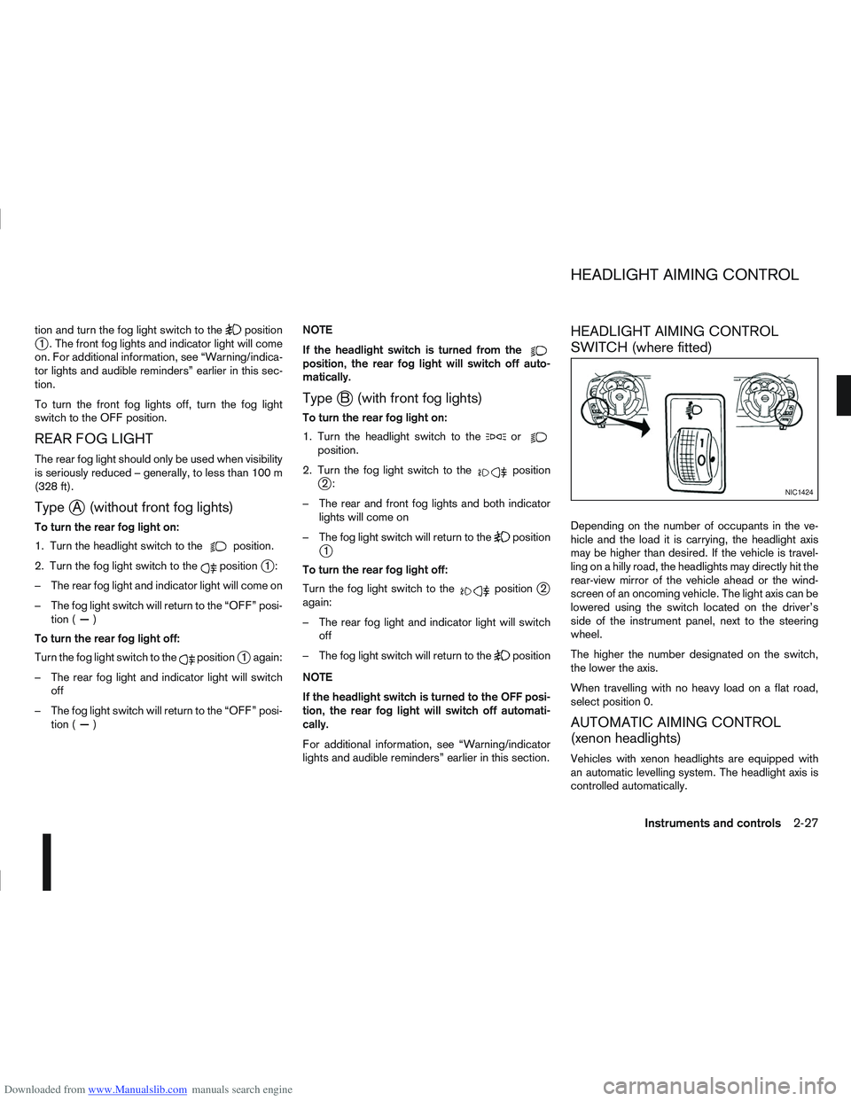
Depending on the number of occupants in the ve-
hicle and the load it is carrying, the headlight axis
may be higher than desired. If the vehicle is travel-
ling on a hilly road, the headlights may directly hit the
rear-view mirror of the vehicle ahead or the wind-
screen of an oncoming vehicle. The light axis can be
lowered using the switch located on the driver’s
side of the instrument panel, next to the steering
wheel.
The higher the number designated on the switch,
the lower the axis.
When travelling with no heavy load on a flat road,
select position 0.
AUTOMATIC AIMING CONTROL
(xenon headlights)
Vehicles with xenon headlights are equipped with
an automatic levelling system. The headlight axis is
controlled automatically.
NIC1424
HEADLIGHT AIMING CONTROL
Instruments and controls2-27
Page 77 of 297
Downloaded from www.Manualslib.com manuals search engine NISSAN recommends consulting local regulations
on the use of lights.To clean the headlights, pull the windscreen washer
switch towards you while the headlight switch is in
the
position and the ignition switch is in the ON
position.
NOTE
The headlight cleaner will automatically operate
every fifth operation of the wiper and washer
switch.
See “Wiper and washer switch” earlier in this sec-
tion
CAUTION
Do not operate the cleaner continuously for
more than 15 seconds.
Do not operate the cleaner if the washer fluid
reservoir is empty or frozen.
See “Window washer fluid/headlight cleaner fluid
(where fitted)” in the “8. Maintenance and
do-it-yourself” section for details on refilling the res-
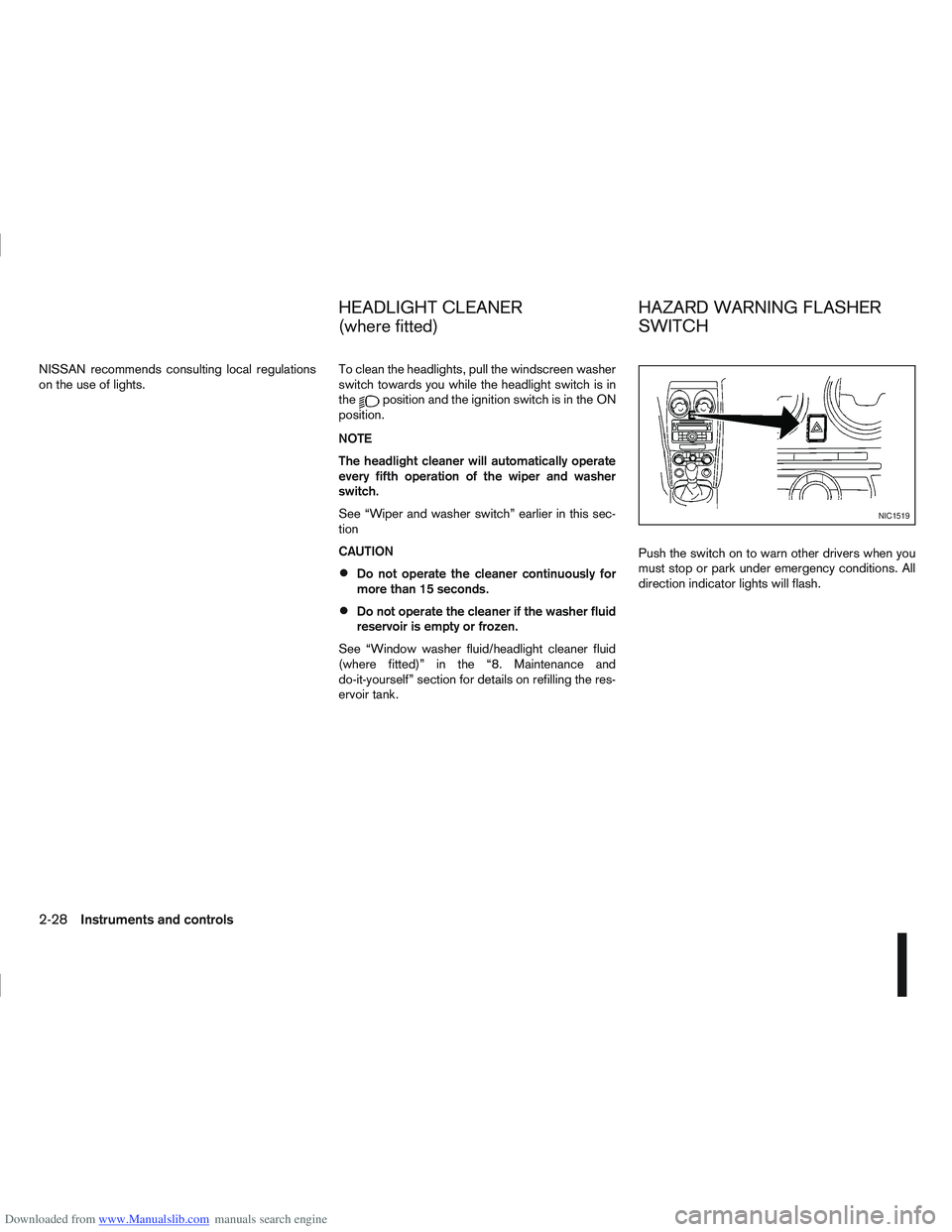
ervoir tank. Push the switch on to warn other drivers when you
must stop or park under emergency conditions. All
direction indicator lights will flash.
NIC1519
HEADLIGHT CLEANER
(where fitted)
HAZARD WARNING FLASHER
SWITCH
2-28Instruments and controls
Page 79 of 297
Downloaded from www.Manualslib.com manuals search engine WARNING
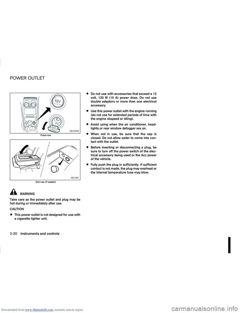
Take care as the power outlet and plug may be
hot during or immediately after use.
CAUTION
This power outlet is not designed for use with
a cigarette lighter unit.
Do not use with accessories that exceed a 12
volt, 120 W (10 A) power draw. Do not use
double adaptors or more than one electrical
accessory.
Use this power outlet with the engine running
(do not use for extended periods of time with
the engine stopped or idling).
Avoid using when the air conditioner, head-
lights or rear window defogger are on.
When not in use, be sure that the cap is
closed. Do not allow water to come into con-
tact with the outlet.
Before inserting or disconnecting a plug, be
sure to turn off the power switch of the elec-
trical accessory being used or the Acc power
of the vehicle.
Fully push the plug in sufficiently. If sufficient
contact is not made, the plug may overheat or
the internal temperature fuse may blow.
NIC1372Z
Front row
NIC1451
2nd row (7-seater)
POWER OUTLET
2-30Instruments and controls
Page 80 of 297
Downloaded from www.Manualslib.com manuals search engine STORAGE TRAYS
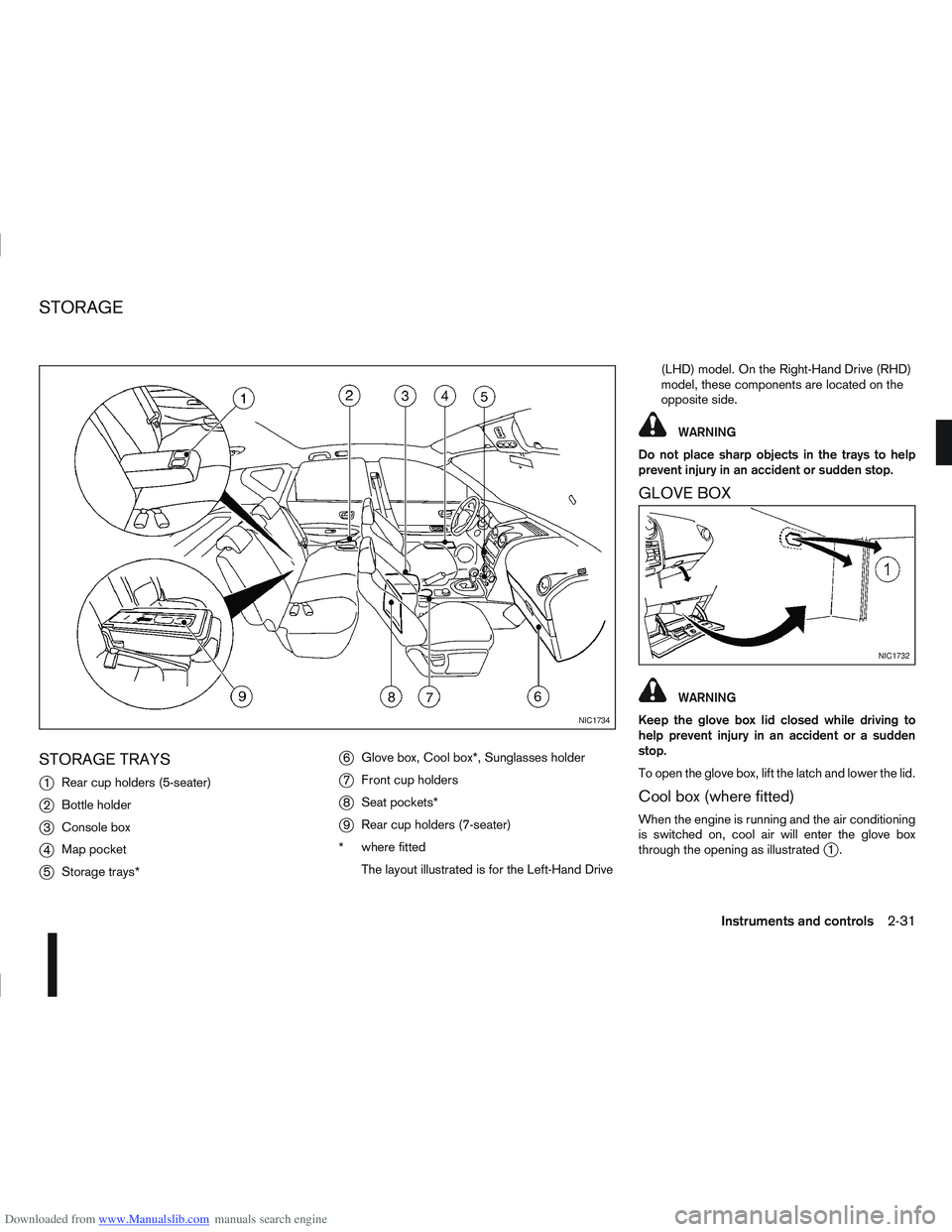
j
1Rear cup holders (5-seater)
j2Bottle holder
j3Console box
j4Map pocket
j5Storage trays*
j6Glove box, Cool box*, Sunglasses holder
j7Front cup holders
j8Seat pockets*
j9Rear cup holders (7-seater)
* where fitted
The layout illustrated is for the Left-Hand Drive (LHD) model. On the Right-Hand Drive (RHD)
model, these components are located on the
opposite side.
WARNING
Do not place sharp objects in the trays to help
prevent injury in an accident or sudden stop.
GLOVE BOX
WARNING
Keep the glove box lid closed while driving to
help prevent injury in an accident or a sudden
stop.
To open the glove box, lift the latch and lower the lid.
Cool box (where fitted)
When the engine is running and the air conditioning
is switched on, cool air will enter the glove box
through the opening as illustrated
j1.
NIC1734
NIC1732
STORAGE
Instruments and controls2-31
Page 81 of 297
Downloaded from www.Manualslib.com manuals search engine Sunglasses holder
WARNING
The sunglasses holder should not be used
while driving so that full attention may be given
to vehicle operation.
Do not leave sunglasses in the sunglasses
holder while parking in direct sunlight. The
heat may damage the sunglasses.
The glove box contains a sunglasses storage area,
which is accessible when the glove box is open.
CONSOLE BOX
WARNING
The centre console box should not be used while
driving so that full attention may be given to ve-
hicle operation.
Pull the lid up to open the console box.
CUP HOLDERS
WARNING
Cup holders should not be used while driving so
that full attention may be given to vehicle opera-
tion.
To access the rear cup holders (where fitted), lower
the centre armrest. CAUTION
Avoid abrupt starting and braking when the
cup holder is being used to prevent spillage.
If the liquid is hot, it can scald you or your pas-
senger.
Use only soft cups in the cup holder. Hard
objects can injure you in an accident.
BOTTLE HOLDER
CAUTION
Do not use the bottle holder for any other
objects that could be thrown about in the ve-
hicle and possibly injure people during sud-
den braking or an accident.
Do not use the bottle holder for open liquid
containers.
MAP POCKET (where fitted)
Map pockets are located in the doors.
SEAT POCKET (where fitted)
A seat pocket (where fitted) is located on the back
or side of the driver and/or passenger seat.
ROOF RAIL (where fitted)
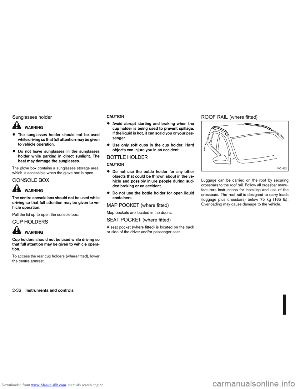
Luggage can be carried on the roof by securing
crossbars to the roof rail. Follow all crossbar manu-
facturers instructions for installing and use of the
crossbars. The roof rail is designed to carry loads
(luggage plus crossbars) below 75 kg (165 lb).
Overloading may cause damage to the vehicle.
NIC1452
2-32Instruments and controls
Page 82 of 297
Downloaded from www.Manualslib.com manuals search engine WARNING
Never put anything on the rear parcel shelf, no
matter how small. Any object on it could cause
an injury in an accident or when the brakes are
applied suddenly.
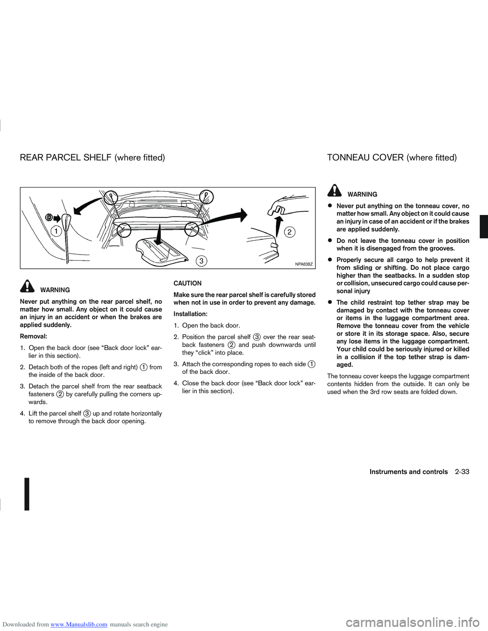
Removal:
1. Open the back door (see “Back door lock” ear- lier in this section).
2. Detach both of the ropes (left and right)
j1 from
the inside of the back door.
3. Detach the parcel shelf from the rear seatback fasteners
j2 by carefully pulling the corners up-
wards.
4. Lift the parcel shelf
j3 up and rotate horizontally
to remove through the back door opening. CAUTION
Make sure the rear parcel shelf is carefully stored
when not in use in order to prevent any damage.
Installation:
1. Open the back door.
2. Position the parcel shelf
j3 over the rear seat-
back fastenersj2 and push downwards until
they “click” into place.
3. Attach the corresponding ropes to each side
j1
of the back door.
4. Close the back door (see “Back door lock” ear- lier in this section).
WARNING
Never put anything on the tonneau cover, no
matter how small. Any object on it could cause
an injury in case of an accident or if the brakes
are applied suddenly.
Do not leave the tonneau cover in position
when it is disengaged from the grooves.
Properly secure all cargo to help prevent it
from sliding or shifting. Do not place cargo
higher than the seatbacks. In a sudden stop
or collision, unsecured cargo could cause per-
sonal injury
The child restraint top tether strap may be
damaged by contact with the tonneau cover
or items in the luggage compartment area.
Remove the tonneau cover from the vehicle
or store it in its storage space. Also, secure
any lose items in the luggage compartment.
Your child could be seriously injured or killed
in a collision if the top tether strap is dam-
aged.
The tonneau cover keeps the luggage compartment
contents hidden from the outside. It can only be
used when the 3rd row seats are folded down.
NPA838Z
REAR PARCEL SHELF (where fitted) TONNEAU COVER (where fitted)
Instruments and controls2-33