instrument panel NISSAN TEANA 2014 Service Manual
[x] Cancel search | Manufacturer: NISSAN, Model Year: 2014, Model line: TEANA, Model: NISSAN TEANA 2014Pages: 4801, PDF Size: 51.2 MB
Page 1 of 4801
A
B
C
D
E
F
G
H
I
J
K
L
M
N
P
O
QUICK REFERENCE INDEX
AGENERAL INFORMATIONGIGeneral Information
BENGINEEMEngine Mechanical
LUEngine Lubrication System
COEngine Cooling System
ECEngine Control System
FLFuel System
EXExhaust System
STRStarting System
ACCAccelerator Control System
CHYBRIDHBCHybrid Control System
DTRANSMISSION & DRIVE-LINECLClutch System
TMTransaxle & Transmission
DLNDriveline
FAXFront Axle
RAXRear Axle
ESUSPENSIONFSUFront Suspension
RSURear Suspension
SCSSuspension Control System
WTRoad Wheels & Tires
FBRAKESBRBrake System
PBParking Brake System
BRCBrake Control System
GSTEERINGSTSteering System
STCSteering Control System
HRESTRAINTSSBSeat Belt
SBCSeat Belt Control System
SRSRS Airbag
SRCSRS Airbag Control System
IVENTILATION, HEATER &
AIR CONDITIONERVTLVentilation System
HAHeater & Air Conditioning System
HACHeater & Air Conditioning Control System
JBODY INTERIORINTInterior
IPInstrument Panel
SESeat
ADPAutomatic Drive Positioner
KBODY EXTERIOR, DOORS, ROOF & VEHICLE
SECURITYDLKDoor & Lock
SECSecurity Control System
GWGlass & Window System
PWCPower Window Control System
RFRoof
EXTExterior
BRMBody Repair Manual
LDRIVER CONTROLSMIRMirrors
EXLExterior Lighting System
INLInterior Lighting System
WWWiper & Washer
DEFDefogger
HRNHorn
MELECTRICAL & POWER
CONTROLPWOPower Outlet
BCSBody Control System
LANLAN System
PCSPower Control System
CHGCharging System
PGPower Supply, Ground & Circuit Elements
NDRIVER INFORMATION &
MULTIMEDIAMWIMeter, Warning Lamp & Indicator
WCSWarning Chime System
SNSonar System
AVAudio, Visual & Navigation System
OCRUISE CONTROLCCSCruise Control System
DASDriver Assistance System
PMAINTENANCEMAMaintenance
All rights reserved. No part
of this Service Manual may
be reproduced or stored in a
retrieval system, or transmit-
ted in any form, or by any
means, electronic, mechani-
cal, photo-copying, record-
ing or otherwise, without the
prior written permission of
Nissan North America, Inc.
Edition: August 2013
Revision: November 2013
Pub. No. SM14E00L33U1
Page 114 of 4801
BR-18
< REMOVAL AND INSTALLATION >
BRAKE PEDAL
REMOVAL AND INSTALLATION
BRAKE PEDAL
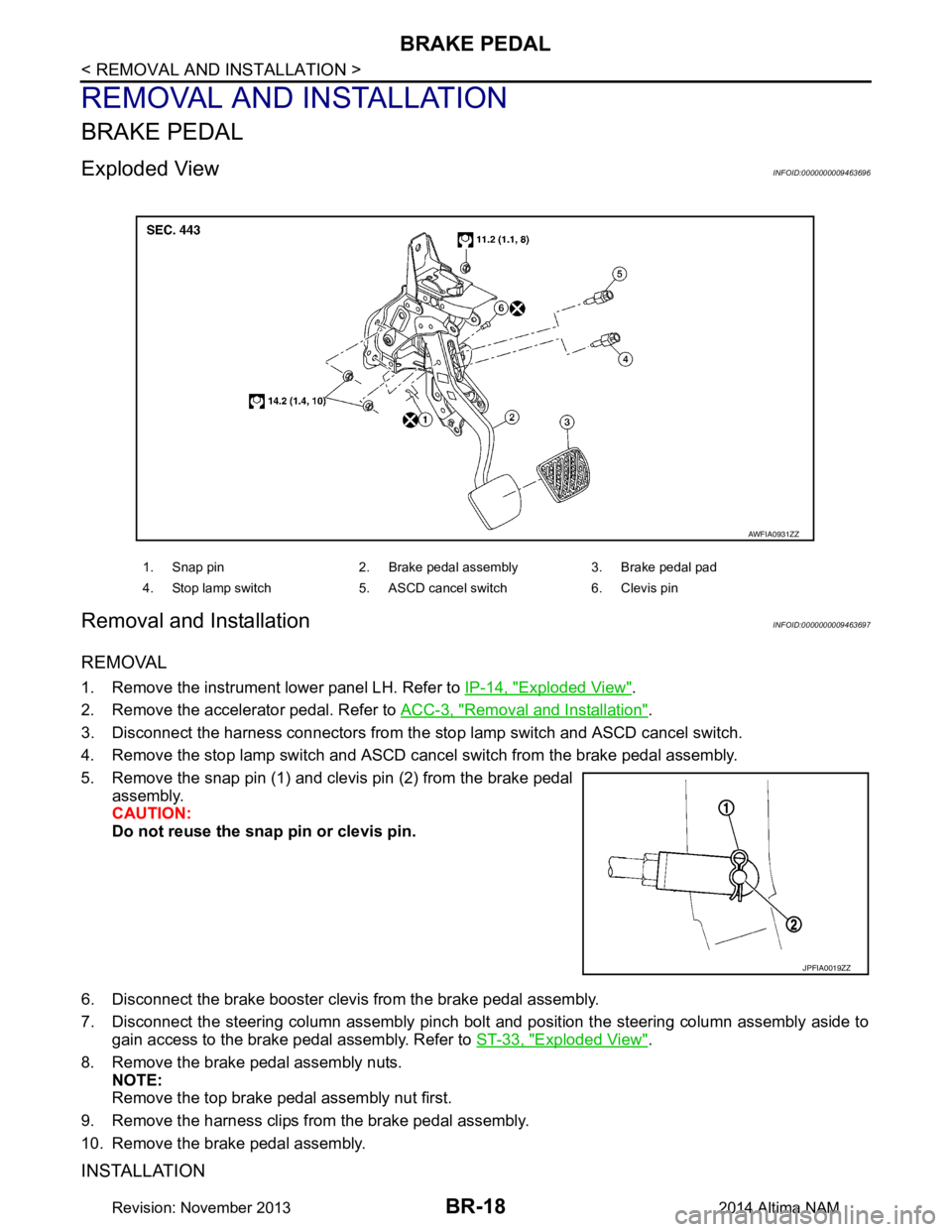
Exploded ViewINFOID:0000000009463696
Removal and InstallationINFOID:0000000009463697
REMOVAL
1. Remove the instrument lower panel LH. Refer to IP-14, "Exploded View".
2. Remove the accelerator pedal. Refer to ACC-3, "Removal and Installation"
.
3. Disconnect the harness connectors from the stop lamp switch and ASCD cancel switch.
4. Remove the stop lamp switch and ASCD canc el switch from the brake pedal assembly.
5. Remove the snap pin (1) and clevis pin (2) from the brake pedal assembly.
CAUTION:
Do not reuse the snap pin or clevis pin.
6. Disconnect the brake booster clevis from the brake pedal assembly.
7. Disconnect the steering column assembly pinch bolt and position the steering column assembly aside to
gain access to the brake pedal assembly. Refer to ST-33, "Exploded View"
.
8. Remove the brake pedal assembly nuts. NOTE:
Remove the top brake pedal assembly nut first.
9. Remove the harness clips from the brake pedal assembly.
10. Remove the brake pedal assembly.
INSTALLATION
1. Snap pin 2. Brake pedal assembly 3. Brake pedal pad
4. Stop lamp switch 5. ASCD cancel switch 6. Clevis pin
AWFIA0931ZZ
JPFIA0019ZZ
Revision: November 20132014 Altima NAM
Page 124 of 4801
BR-28
< REMOVAL AND INSTALLATION >
BRAKE BOOSTER
BRAKE BOOSTER
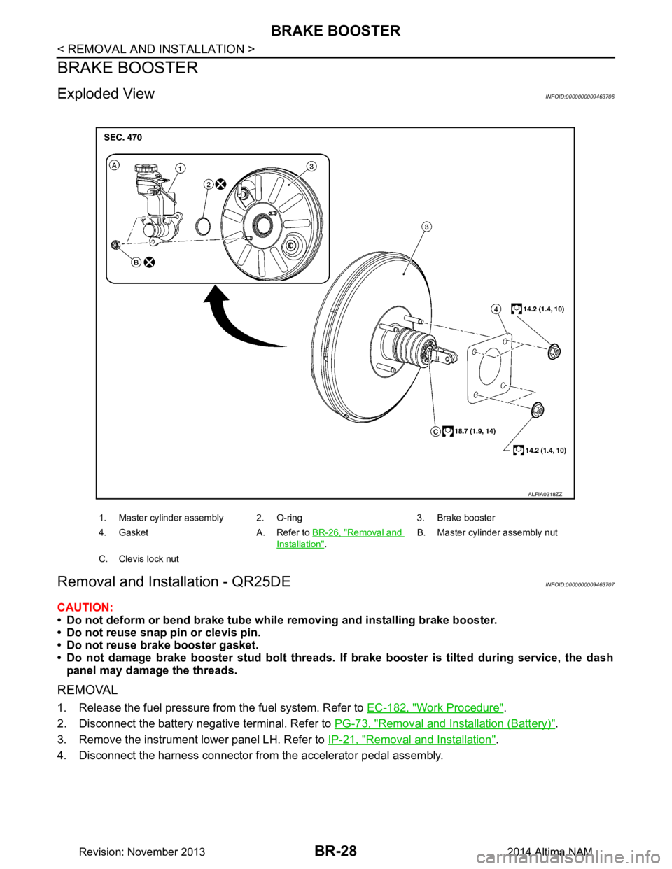
Exploded ViewINFOID:0000000009463706
Removal and Installation - QR25DEINFOID:0000000009463707
CAUTION:
• Do not deform or bend brake tube whil e removing and installing brake booster.
• Do not reuse snap pin or clevis pin.
• Do not reuse brake booster gasket.
• Do not damage brake booster stud bolt threads. If brake booster is tilted during service, the dash
panel may damage the threads.
REMOVAL
1. Release the fuel pressure from the fuel system. Refer to EC-182, "Work Procedure".
2. Disconnect the battery negative terminal. Refer to PG-73, "Removal and Installation (Battery)"
.
3. Remove the instrument lower panel LH. Refer to IP-21, "Removal and Installation"
.
4. Disconnect the harness connector from the accelerator pedal assembly.
1. Master cylinder assembly 2. O-ring 3. Brake booster
4. Gasket A. Refer to BR-26, "Removal and
Installation".B. Master cylinder assembly nut
C. Clevis lock nut
ALFIA0318ZZ
Revision: November 20132014 Altima NAM
Page 126 of 4801

BR-30
< REMOVAL AND INSTALLATION >
BRAKE BOOSTER
2. Disconnect the battery negative cable. Refer to PG-73, "Removal and Installation (Battery)".
3. Remove the instrument lower panel LH. Refer to IP-21, "Removal and Installation"
.
4. Remove accelerator pedal assembly. Refer to ACC-3, "Removal and Installation"
.
5. Remove the brake pedal. Refer to BR-18, "Removal and Installation"
.
6. Loosen the clevis lock nut (A) and remove the clevis bracket (B) from the input rod (C).
7. Remove the brake master cylinder. Refer to BR-26, "Removal and Installation"
.
8. Remove the vacuum hose. Refer to BR-31, "Exploded View"
.
9. Disconnect the fuel line main connections. Refer to FL-5, "Quick Connector"
.
10. Remove the cowl top. Refer to EXT-24, "Removal and Installation"
.
11. Remove the strut tower bar. Refer to FSU-19, "Exploded View"
.
12. Remove the wiper drive assembly. Refer to WW-64, "Removal and Installation"
.
13. Remove the cowl top extension.
14. Disconnect the active boost sensor harness connector.
15. Remove the brake booster.
16. Remove and discard the brake booster gasket. CAUTION:
Do not reuse brake booster gasket.
INSTALLATION
Installation is in the reverse order of removal.
• Prior to installation, loosen clevis lock nut (1) and adjust input rod (2) to the specified value (B).
• After input rod adjustment (B), temporarily tighten clevis lock nut for installation of brake booster.
• Connect the battery negative terminal. Refer to PG-7, "ADDITIONAL SERVICE WHEN REMOVING BAT-
TERY NEGATIVE TERMINAL : Special Repair Requirement".
:Front
ALFIA0319ZZ
Length (B) : Refer to BR-49, "Brake Booster".
ALFIA0299ZZ
Revision: November 20132014 Altima NAM
Page 276 of 4801
![NISSAN TEANA 2014 Service Manual
BRC-130
< REMOVAL AND INSTALLATION >[VDC/TCS/ABS]
VDC OFF SWITCH
VDC OFF SWITCH
Removal and InstallationINFOID:0000000009463854
REMOVAL
1. Remove the instrument lower panel LH. Refer to
IP-21, "Remo NISSAN TEANA 2014 Service Manual
BRC-130
< REMOVAL AND INSTALLATION >[VDC/TCS/ABS]
VDC OFF SWITCH
VDC OFF SWITCH
Removal and InstallationINFOID:0000000009463854
REMOVAL
1. Remove the instrument lower panel LH. Refer to
IP-21, "Remo](/img/5/57390/w960_57390-275.png)
BRC-130
< REMOVAL AND INSTALLATION >[VDC/TCS/ABS]
VDC OFF SWITCH
VDC OFF SWITCH
Removal and InstallationINFOID:0000000009463854
REMOVAL
1. Remove the instrument lower panel LH. Refer to
IP-21, "Removal and Installation".
2. Remove the switch plate screw s and remove the switch plate.
3. Release pawls (B) using suitable tool and remove the VDC OFF switch (A).
: pawl
INSTALLATION
Installation is in the reverse order of removal.
ALFIA0307ZZ
Revision: November 20132014 Altima NAMRevision: November 20132014 Altima NAM
Page 284 of 4801
BRM-6
< PRECAUTION >
HANDLING PRECAUTIONS FOR PLASTICS
3. Front combination lampLens PC Polycarbonate
Housing PP Polypropylene
4. Front bumper fascia PP + EPM Polypropylene + Ethylene Propylene (Di-
ene) copolymer
5. Rear combination lamp Lens PMMA Poly Methyl Methacrylate
Housing ABS Acronitrile Butadiene Acrylate
6. Rear bumper fascia PP + EPM Polypropylene + Ethylene Propylene (Di-
ene) copolymer
7. License lamp finisher ABS + PC Acronitrile Butadiene Acrylate + Polycar-
bonate
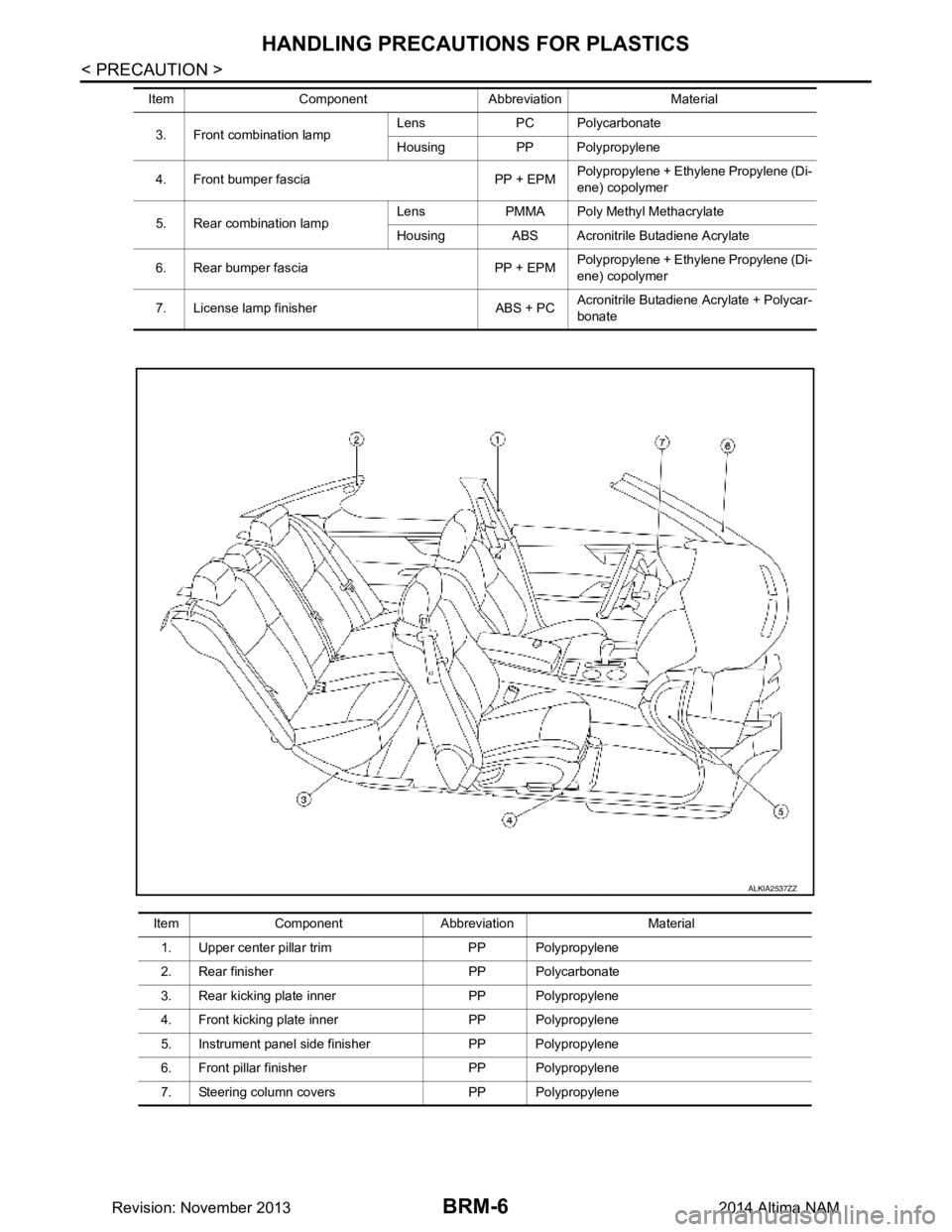
Item Component Abbreviation Material
Item Component Abbreviation Material
1. Upper center pillar trim PP Polypropylene
2. Rear finisher PP Polycarbonate
3. Rear kicking plate inner PP Polypropylene
4. Front kicking plate inner PP Polypropylene
5. Instrument panel side finisher PP Polypropylene
6. Front pillar finisher PP Polypropylene
7. Steering column covers PP Polypropylene
ALKIA2537ZZ
Revision: November 20132014 Altima NAM
Page 575 of 4801
![NISSAN TEANA 2014 Service Manual
DAS-142
< REMOVAL AND INSTALLATION >[LDW]
WARNING SYSTEMS SWITCH
REMOVAL AND INSTALLATION
WARNING SYSTEMS SWITCH
Removal and InstallationINFOID:0000000009464796
REMOVAL
1. Remove the instrument lower NISSAN TEANA 2014 Service Manual
DAS-142
< REMOVAL AND INSTALLATION >[LDW]
WARNING SYSTEMS SWITCH
REMOVAL AND INSTALLATION
WARNING SYSTEMS SWITCH
Removal and InstallationINFOID:0000000009464796
REMOVAL
1. Remove the instrument lower](/img/5/57390/w960_57390-574.png)
DAS-142
< REMOVAL AND INSTALLATION >[LDW]
WARNING SYSTEMS SWITCH
REMOVAL AND INSTALLATION
WARNING SYSTEMS SWITCH
Removal and InstallationINFOID:0000000009464796
REMOVAL
1. Remove the instrument lower panel LH. Refer to
IP-21, "Removal and Installation".
2. Remove screws ( ) that retain the upper switch carrier (1) to the instrument lower panel LH (2).
3. Release upper tab (B) and lower tab (C) using a suitable tool (A), then remove the warning system switch (4) from the upper
switch carrier.
(1) Trunk opener switch
(2) VDC switch
(3) Heated steering wheel switch
INSTALLATION
Installation is in the reverse order of removal.
ALOIA0143ZZ
ALOIA0144ZZ
Revision: November 20132014 Altima NAMRevision: November 20132014 Altima NAM
Page 650 of 4801
![NISSAN TEANA 2014 Service Manual
DAS
WARNING SYSTEMS SWITCHDAS-217
< REMOVAL AND INSTALLATION > [BSW]
C
D E
F
G H
I
J
K L
M B
N P
A
REMOVAL AND INSTALLATION
WARNING SYSTEMS SWITCH
Removal and InstallationINFOID:0000000009464878
RE NISSAN TEANA 2014 Service Manual
DAS
WARNING SYSTEMS SWITCHDAS-217
< REMOVAL AND INSTALLATION > [BSW]
C
D E
F
G H
I
J
K L
M B
N P
A
REMOVAL AND INSTALLATION
WARNING SYSTEMS SWITCH
Removal and InstallationINFOID:0000000009464878
RE](/img/5/57390/w960_57390-649.png)
DAS
WARNING SYSTEMS SWITCHDAS-217
< REMOVAL AND INSTALLATION > [BSW]
C
D E
F
G H
I
J
K L
M B
N P
A
REMOVAL AND INSTALLATION
WARNING SYSTEMS SWITCH
Removal and InstallationINFOID:0000000009464878
REMOVAL
1. Remove the instrument lower panel LH. Refer to IP-21, "Removal and Installation".
2. Remove screws ( ) that retain the upper switch carrier (1) to the instrument lower panel LH (2).
3. Release upper tab (B) and lower tab (C) using a suitable tool (A), then remove the warning system switch (4) from the upper
switch carrier.
(1) Trunk opener switch
(2) VDC switch
(3) Heated steering wheel switch
INSTALLATION
Installation is in the reverse order of removal.
ALOIA0143ZZ
ALOIA0144ZZ
Revision: November 20132014 Altima NAMRevision: November 20132014 Altima NAM
Page 798 of 4801
DLK-30
< SYSTEM DESCRIPTION >
SYSTEM (INTELLIGENT KEY SYSTEM)
*: If the door closing impact shocks the door lock knob or contacts against baggage with the door lock knob might activate the door locks
accidentally but unlock operation is performed in these cases.
CAUTION:
• The above function operates when the Intelligent Key is inside the vehicle. However, there may be
times when the Intelligent Key can not be detected. This function does not operate when the Intelli-
gent Key is on the instrument panel, rear parcel shelf or in the glove box. Also, this system some-
times does not operate if the Intelligent Key is in the door pocket for the open door.
REMOTE ENGINE START FUNCTION
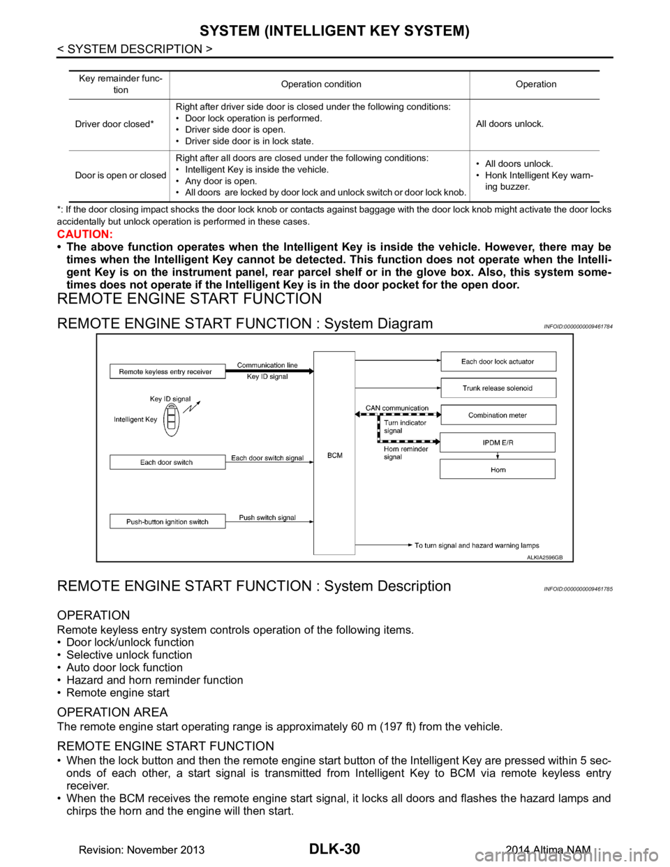
REMOTE ENGINE START FUNCTION : System DiagramINFOID:0000000009461784
REMOTE ENGINE START FUNCTION : System DescriptionINFOID:0000000009461785
OPERATION
Remote keyless entry system controls operation of the following items.
• Door lock/unlock function
• Selective unlock function
• Auto door lock function
• Hazard and horn reminder function
• Remote engine start
OPERATION AREA
The remote engine start operating range is approximately 60 m (197 ft) from the vehicle.
REMOTE ENGINE START FUNCTION
• When the lock button and then the remote engine start button of the Intelligent Key are pressed within 5 sec-
onds of each other, a start signal is transmitted from Intelligent Key to BCM via remote keyless entry
receiver.
• When the BCM receives the remote engine start signal , it locks all doors and flashes the hazard lamps and
chirps the horn and the engine will then start.
Key remainder func-
tion Operation condition Operation
Driver door closed* Right after driver side door is closed under the following conditions:
• Door lock operation is performed.
• Driver side door is open.
• Driver side door is in lock state. All doors unlock.
Door is open or closed Right after all doors are closed under the following conditions:
• Intelligent Key is inside the vehicle.
• Any door is open.
• All doors are locked by door lock and unlock switch or door lock knob. • All doors unlock.
• Honk Intelligent Key warn- ing buzzer.
ALKIA2596GB
Revision: November 20132014 Altima NAMRevision: November 20132014 Altima NAM
Page 806 of 4801
DLK-38
< SYSTEM DESCRIPTION >
SYSTEM (INTELLIGENT KEY SYSTEM)
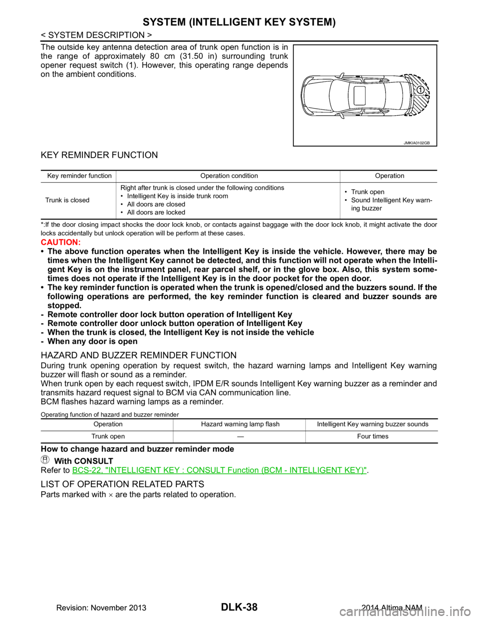
The outside key antenna detection area of trunk open function is in
the range of approximately 80 cm (31.50 in) surrounding trunk
opener request switch (1). However, this operating range depends
on the ambient conditions.
KEY REMINDER FUNCTION
*:If the door closing impact shocks the door lock knob, or contacts against baggage with the door lock knob, it might activate the door
locks accidentally but unlock operation will be perform at these cases.
CAUTION:
• The above function operates when the Intelligent Key is inside the vehicle. However, there may be
times when the Intelligent Key cannot be detected, an d this function will not operate when the Intelli-
gent Key is on the instrument panel, rear parcel shelf, or in the glove box. Also, this system some-
times does not operate if the Intelligent Key is in the door pocket for the open door.
• The key reminder function is operated when the tr unk is opened/closed and the buzzers sound. If the
following operations are performed, the key remind er function is cleared and buzzer sounds are
stopped.
- Remote controller door lock butt on operation of Intelligent Key
- Remote controller door unlock butt on operation of Intelligent Key
- When the trunk is closed, the Intell igent Key is not inside the vehicle
- When any door is open
HAZARD AND BUZZER REMINDER FUNCTION
During trunk opening operation by request switch, the hazard warning lamps and Intelligent Key warning
buzzer will flash or sound as a reminder.
When trunk open by each request switch , IPDM E/R sounds Intelligent Key warning buzzer as a reminder and
transmits hazard request signal to BCM via CAN communication line.
BCM flashes hazard warning lamps as a reminder.
Operating function of hazard and buzzer reminder
How to change hazard and buzzer reminder mode
With CONSULT
Refer to BCS-22, "INTELLIGENT KEY : CONSULT Function (BCM - INTELLIGENT KEY)"
.
LIST OF OPERATION RELATED PARTS
Parts marked with × are the parts related to operation.
JMKIA0102GB
Key reminder function Operation condition Operation
Trunk is closed Right after trunk is closed under the following conditions
• Intelligent Key is inside trunk room
• All doors are closed
• All doors are locked • Trunk open
• Sound Intelligent Key warn-
ing buzzer
Operation Hazard warning lamp flash Intelligent Key warning buzzer sounds
Trunk open — Four times
Revision: November 20132014 Altima NAMRevision: November 20132014 Altima NAM