night vision NISSAN TEANA 2014 Service Manual
[x] Cancel search | Manufacturer: NISSAN, Model Year: 2014, Model line: TEANA, Model: NISSAN TEANA 2014Pages: 4801, PDF Size: 51.2 MB
Page 2573 of 4801

SERVICE INFORMATION FOR ELECTRICAL INCIDENTGI-45
< BASIC INSPECTION >
C
D E
F
G H
I
J
K L
M B
GI
N
O P
An unclamped or loose harness can cause wiring to be pinched by seat components (such as slide guides)
during vehicle vibration. If the wiring runs under s eating areas, inspect wire routing for possible damage or
pinching.
HEAT SENSITIVE
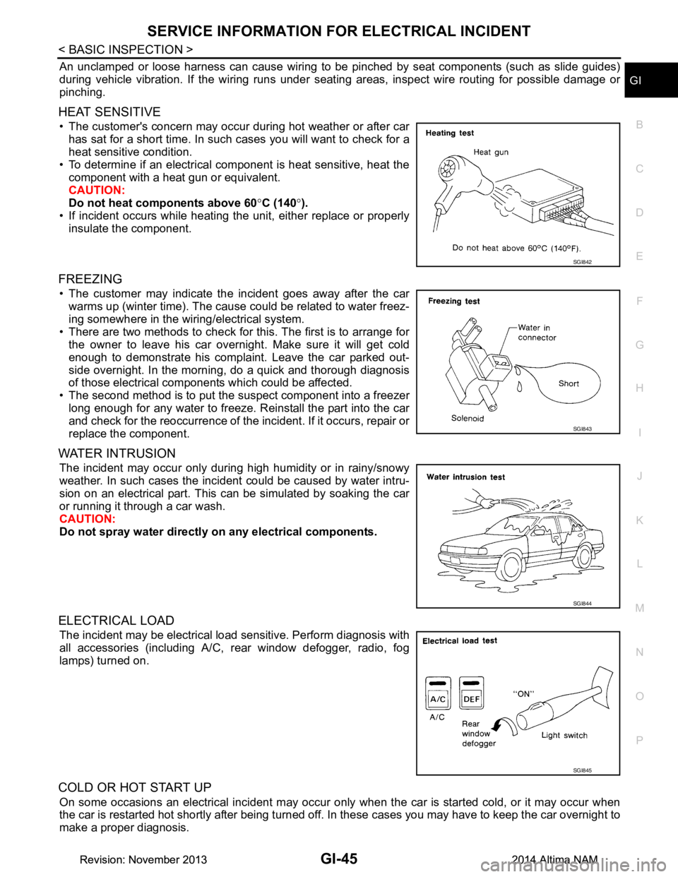
• The customer's concern may occur during hot weather or after car has sat for a short time. In such cases you will want to check for a
heat sensitive condition.
• To determine if an electrical component is heat sensitive, heat the component with a heat gun or equivalent.
CAUTION:
Do not heat components above 60 °C (140 °).
• If incident occurs while heating t he unit, either replace or properly
insulate the component.
FREEZING
• The customer may indicate the incident goes away after the car warms up (winter time). The cause could be related to water freez-
ing somewhere in the wiring/electrical system.
• There are two methods to check for this. The first is to arrange for the owner to leave his car overnight. Make sure it will get cold
enough to demonstrate his complaint. Leave the car parked out-
side overnight. In the morning, do a quick and thorough diagnosis
of those electrical components which could be affected.
• The second method is to put the suspect component into a freezer long enough for any water to freeze. Reinstall the part into the car
and check for the reoccurrence of the incident. If it occurs, repair or
replace the component.
WATER INTRUSION
The incident may occur only during high humidity or in rainy/snowy
weather. In such cases the incident could be caused by water intru-
sion on an electrical part. This c an be simulated by soaking the car
or running it through a car wash.
CAUTION:
Do not spray water directly on any electrical components.
ELECTRICAL LOAD
The incident may be electrical load sensitive. Perform diagnosis with
all accessories (including A/C, rear window defogger, radio, fog
lamps) turned on.
COLD OR HOT START UP
On some occasions an electrical incident may occur only when the car is started cold, or it may occur when
the car is restarted hot shortly after being turned off. In these cases you may have to keep the car overnight to
make a proper diagnosis.
SGI842
SGI843
SGI844
SGI845
Revision: November 20132014 Altima NAMRevision: November 20132014 Altima NAM
Page 3266 of 4801

MWI
SYSTEMMWI-11
< SYSTEM DESCRIPTION >
C
D E
F
G H
I
J
K L
M B
A
O P
SPEEDOMETER
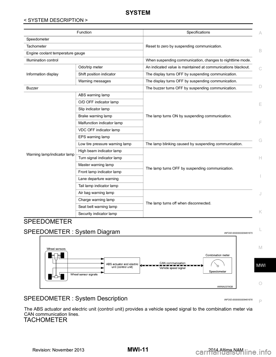
SPEEDOMETER : System DiagramINFOID:0000000009461675
SPEEDOMETER : System DescriptionINFOID:0000000009461676
The ABS actuator and electric unit (control unit) provi des a vehicle speed signal to the combination meter via
CAN communication lines.
TACHOMETER
Function Specifications
Speedometer Reset to zero by suspending communication.
Tachometer
Engine coolant temperature gauge
Illumination control When suspending communication, changes to nighttime mode.
Information display Odo/trip meter An indicated value is maintained at communications blackout.
Shift position indicator The display turns OFF by suspending communication.
Warning messages The display turns OFF by suspending communication.
Buzzer The buzzer turns OFF by suspending communication.
Warning lamp/indicator lamp ABS warning lamp
The lamp turns ON by suspending communication.
O/D OFF indicator lamp
Slip indicator lamp
Brake warning lamp
Malfunction indicator lamp
VDC OFF indicator lamp
EPS warning lamp
Low tire pressure warning lamp The lamp blinking caused by suspending communication.
High beam indicator lamp
The lamp turns OFF by suspending communication.
Turn signal indicator lamp
Master warning lamp
Front lamp indicator lamp
Lane departure warning
Tail lamp indicator lamp
Air bag warning lamp
The lamp turns off when disconnected.
Charge warning lamp
Seat belt warning lamp
Security indicator lamp
AWNIA2379GB
Revision: November 20132014 Altima NAMRevision: November 20132014 Altima NAM
Page 3268 of 4801

MWI
SYSTEMMWI-13
< SYSTEM DESCRIPTION >
C
D E
F
G H
I
J
K L
M B
A
O P
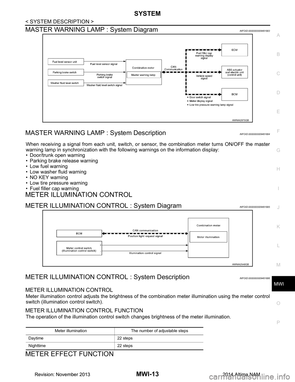
MASTER WARNING LAMP : System DiagramINFOID:0000000009461683
MASTER WARNING LAMP : System DescriptionINFOID:0000000009461684
When receiving a signal from each unit, switch, or s ensor, the combination meter turns ON/OFF the master
warning lamp in synchronization with the following warnings on the information display:
• Door/trunk open warning
• Parking brake release warning
• Low fuel warning
• Low washer fluid warning
• NO KEY warning
• Low tire pressure warning
• Fuel filler cap warning
METER ILLUMINATION CONTROL
METER ILLUMINATION CONTROL : System DiagramINFOID:0000000009461685
METER ILLUMINATION CONTROL : System DescriptionINFOID:0000000009461686
METER ILLUMINATION CONTROL
Meter illumination control adjusts the brightness of the combination meter illumination using the meter control
switch (illumination control switch).
METER ILLUMINATION CONTROL FUNCTION
The operation of the illumination control switch changes brightness of the meter illumination.
METER EFFECT FUNCTION
AWNIA2975GB
AWNIA2548GB
Meter illumination The number of adjustable steps
Daytime 22 steps
Nighttime 22 steps
Revision: November 20132014 Altima NAMRevision: November 20132014 Altima NAM
Page 3282 of 4801

MWI
COMBINATION METERMWI-27
< ECU DIAGNOSIS INFORMATION >
C
D E
F
G H
I
J
K L
M B
A
O PFail-SafeINFOID:0000000009461695
FA I L - S A F E
The combination meter activates the fail-safe contro l if CAN communication with each unit is malfunctioning.
DTC IndexINFOID:0000000009461696
52
(P) Ground O/D OFF/SPORT switch Input Ignition
switch
ON O/D OFF switch pressed 0 V
Other than the above 5 V
Te r m i n a l N o .
(Wire color) Description
ConditionVa l u e
(Approx.)
+ – Signal name Input/
Output
Function Specifications
Speedometer Reset to zero by suspending communication.
Tachometer
Engine coolant temperature gauge
Illumination control When suspending communication, changes to nighttime mode.
Information display Odo/trip meter An indicated value is maintained at communications blackout.
Shift position indicator The display turns OFF by suspending communication.
Warning messages The display turns OFF by suspending communication.
Buzzer The buzzer turns OFF by suspending communication.
Warning lamp/indicator lamp ABS warning lamp
The lamp turns ON by suspending communication.
O/D OFF indicator lamp
Slip indicator lamp
Brake warning lamp
Malfunction indicator lamp
VDC OFF indicator lamp
EPS warning lamp
Low tire pressure warning lamp The lamp blinking caused by suspending communication.
High beam indicator lamp
The lamp turns OFF by suspending communication.
Turn signal indicator lamp
Master warning lamp
Front lamp indicator lamp
Lane departure warning
Tail lamp indicator lamp
Air bag warning lamp
The lamp turns off when disconnected.
Charge warning lamp
Seat belt warning lamp
Security indicator lamp
Display contents of CONSULT Diagnostic item is detected when... Refer to
CAN COMM CIRCUIT
[U1000] When combination meter is not transmitting or receiving CAN communication signal for 2
seconds or more. MWI-53
CONTROL UNIT (CAN)
[U1010] When detecting error during the initial diagnosis of the CAN controller of combination
meter. MWI-54
Revision: November 20132014 Altima NAMRevision: November 20132014 Altima NAM