fuse OPEL FRONTERA 1998 Workshop Manual
[x] Cancel search | Manufacturer: OPEL, Model Year: 1998, Model line: FRONTERA, Model: OPEL FRONTERA 1998Pages: 6000, PDF Size: 97 MB
Page 4699 of 6000
6E–42
ENGINE DRIVEABILITY AND EMISSIONS
Intermittent Malfunction Indicator Lamp
In the case of an “intermittent” fault, the MIL (“Check
Engine” lamp) may illuminate and then (after three trips)
go “OFF”. However, the corresponding diagnostic trouble
code will be stored in the memory. When unexpected
diagnostic trouble codes appear, check for an intermittent
malfunction.
A diagnostic trouble code may reset. Consult the
“Diagnostic Aids” associated with the diagnostic trouble
code. A physical inspection of the applicable sub-system
most often will resolve the problem.
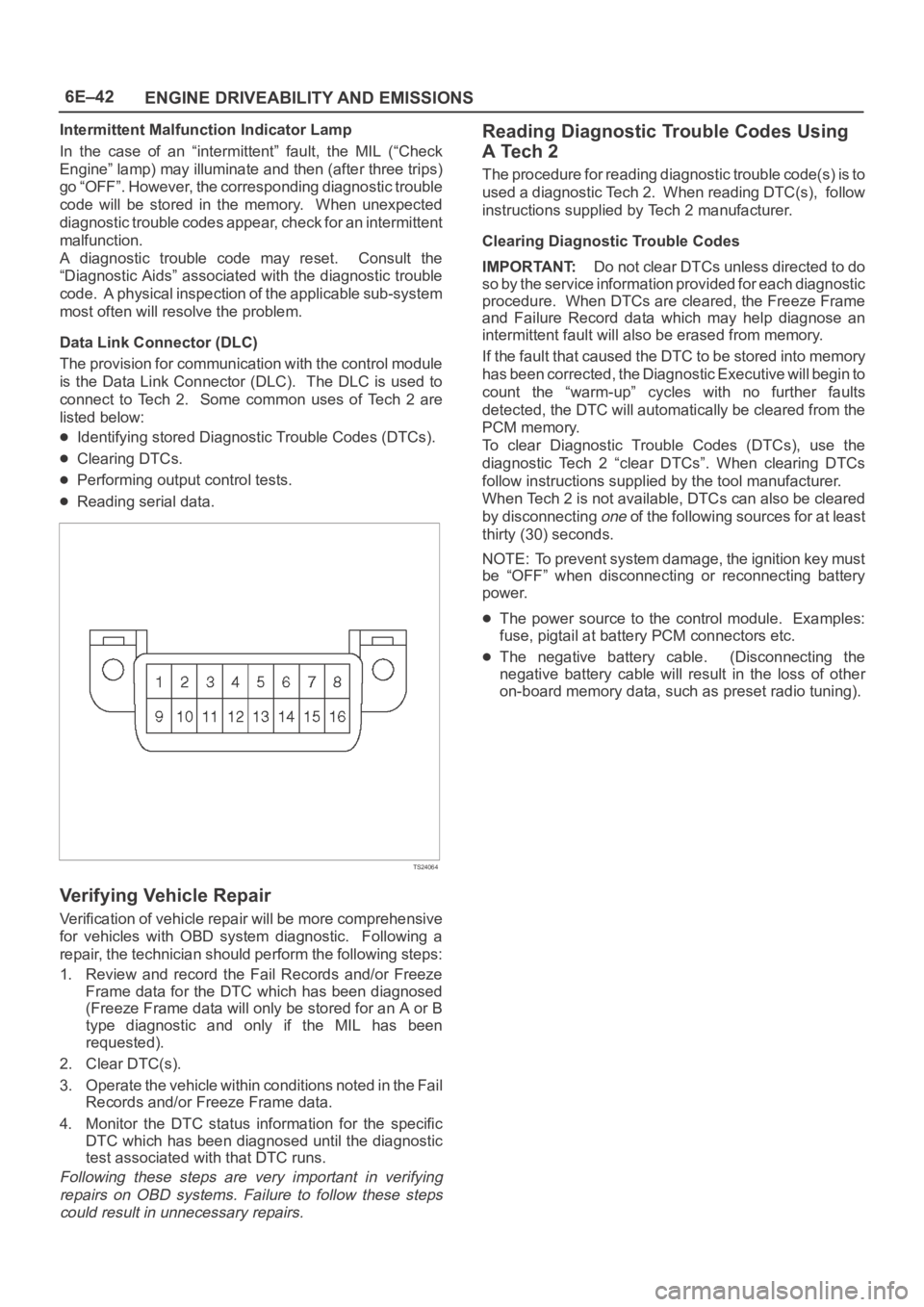
Data Link Connector (DLC)
The provision for communication with the control module
is the Data Link Connector (DLC). The DLC is used to
connect to Tech 2. Some common uses of Tech 2 are
listed below:
Identifying stored Diagnostic Trouble Codes (DTCs).
Clearing DTCs.
Performing output control tests.
Reading serial data.
TS24064
Verifying Vehicle Repair
Verification of vehicle repair will be more comprehensive
for vehicles with OBD system diagnostic. Following a
repair, the technician should perform the following steps:
1. Review and record the Fail Records and/or Freeze
Frame data for the DTC which has been diagnosed
(Freeze Frame data will only be stored for an A or B
type diagnostic and only if the MIL has been
requested).
2. Clear DTC(s).
3. Operate the vehicle within conditions noted in the Fail
Records and/or Freeze Frame data.
4. Monitor the DTC status information for the specific
DTC which has been diagnosed until the diagnostic
test associated with that DTC runs.
Following these steps are very important in verifying
repairs on OBD systems. Failure to follow these steps
could result in unnecessary repairs.
Reading Diagnostic Trouble Codes Using
A Tech 2
The procedure for reading diagnostic trouble code(s) is to
used a diagnostic Tech 2. When reading DTC(s), follow
instructions supplied by Tech 2 manufacturer.
Clearing Diagnostic Trouble Codes
IMPORTANT:Do not clear DTCs unless directed to do
so by the service information provided for each diagnostic
procedure. When DTCs are cleared, the Freeze Frame
and Failure Record data which may help diagnose an
intermittent fault will also be erased from memory.
If the fault that caused the DTC to be stored into memory
has been corrected, the Diagnostic Executive will begin to
count the “warm-up” cycles with no further faults
detected, the DTC will automatically be cleared from the
PCM memory.
To clear Diagnostic Trouble Codes (DTCs), use the
diagnostic Tech 2 “clear DTCs”. When clearing DTCs
follow instructions supplied by the tool manufacturer.
When Tech 2 is not available, DTCs can also be cleared
by disconnecting
one of the following sources for at least
thirty (30) seconds.
NOTE: To prevent system damage, the ignition key must
be “OFF” when disconnecting or reconnecting battery
power.
The power source to the control module. Examples:
fuse, pigtail at battery PCM connectors etc.
The negative battery cable. (Disconnecting the
negative battery cable will result in the loss of other
on-board memory data, such as preset radio tuning).
Page 4713 of 6000

6E–56
ENGINE DRIVEABILITY AND EMISSIONS
A/C Clutch Control Circuit Diagnosis
StepNo Ye s Va l u e ( s ) Action
61. Engine idling.
2. A/C “ON”.
3. Blower “ON”.
4. Observe the “A/C Request” display on the Tech 2.
Does the tool “A/C Request” display indicate “Yes?”
—Go to Step 34Go to Step 7
7Temporarily substitute the A/C compressor relay in
place of the A/C thermostat relay, then repeat Step 5.
Did the “A/C Request” display indicate “Yes?”
—Go to Step 8Go to Step 9
8Replace the original A/C thermostat relay.
Is the action complete?
—Verify repair—
9Dose the blower operate?—Go to Step 10Go to Step 11
10Repair the blower.
Is the action complete?
—Verify repair—
11Check for a faulty 10a A/C fuse in the underdash fuse
panel.
Was the 10A fuse OK?
—Go to Step 13Go to Step 12
12Check for short circuit and make repairs if necessary.
Replace the 10A A/C fuse.
Is the action complete?
—Verify repair—
131. Ignition “ON.”
2. Use a DVM to check voltage at the positive A/C
switch wire (BRN).
Was voltage equal to the specified value?
+BGo to Step 15Go to Step 14
14Repair the open wire (BRN) between the A/C switch
and the A/C fuse.
Is the action complete?
—Verify repair—
151. Remove the glove box to gain access to the A/C
thermostat.
2. Disconnect the thermostat connector.
3. Attach a fused jumper between ground and the
PNK/GRN wire at the thermostat.
4. A/C “ON.”
5. Blower “ON.”
Dose A/C request indicate “YES” on the Tech 2?
—Go to Step 16Go to Step 23
161. Ignition “ON.”
2. Use a DVM to check voltage at the electronic A/C
thermostat.
Was voltage equal to the specified value?
+BGo to Step 20Go to Step 17
17Check for an open (LT GRN) between the thermostat
and the A/C switch.
Was the wire open?
—Go to Step 18Go to Step 19
18Repair the open wire (LT GRN) between the thermostat
and the A/C switch.
Is the action complete?
—Verify repair—
Page 4714 of 6000

6E–57 ENGINE DRIVEABILITY AND EMISSIONS
A/C Clutch Control Circuit Diagnosis
StepNo Ye s Va l u e ( s ) Action
19Replace the A/C switch.
Is the action complete?
—Verify repair—
20Use an ohmmeter to check continuity between the
electronic A/C thermostat and the blower switch.
Was there an open circuit?
—Go to Step 21Go to Step 22
21Repair the open wire (GRN/YEL) between the
thermostat and the blower switch.
Is the action complete?
—Verify repair—
22Replace the electronic A/C thermostat.
Is the an action complete?
—Verify repair—
23Check for an open circuit between A/C thermostat relay
and PCM A/C request terminal (E-15).
Was there an open circuit?
—Go to Step 24Go to Step 25
24Repair the open circuit between the PCM and A/C
thermostat relay.
Is the action complete?
—Verify repair—
25Check for an open circuit between the A/C switch (LT
GRN) and the A/C thermostat relay (LT GRN).
Was there an open circuit?
—Go to Step 26Go to Step 27
26Repair the open circuit between the A/C switch and the
A/C thermostat relay.
Is the action complete?
—Verify repair—
271. Ignition “ON.”
2. Use a DVM to check voltage at the A/C pressure
switch (BRN).
Was voltage equal to the specified value?
+BGo to Step 29Go to Step 28
28Repair the open circuit between the 10A A/C fuse and
the pressure switch.
Is the action complete?
—Verify repair—
29Use an ohmmeter to check continuity between the
pressure switch (GRN/WHT) and the A/C thermostat
relay (GRN/WHT).
Was the circuit open?
—Go to Step 30Go to Step 31
30Repair the open circuit between the pressure switch
and the A/C thermostat relay.
Is the action complete?
—Verify repair—
31Check for damaged pin or terminal at E-15 of the PCM.
Was a damaged pin or terminal found?
—Go to Step 32Go to Step 33
32Repair the damaged pin or terminal.
Is the action complete?
—Verify repair—
33Replace the PCM.
IMPORTANT:The replacement PCM must be
programmed. Refer to
UBS 98model year Immobilizer
Workshop Manual.
Is the action complete?—Verify repair—
Page 4715 of 6000

6E–58
ENGINE DRIVEABILITY AND EMISSIONS
A/C Clutch Control Circuit Diagnosis
StepNo Ye s Va l u e ( s ) Action
341. Remove the A/C compressor relay.
2. Ignition “ON.”
3. Use a DVM to check voltage at both of the BRN
wires at the A/C compressor relay socket.
Is the voltage equal to the specified value?
+BGo to Step 36Go to Step 35
35Repair the faulty BRN wire between the A/C fuse and
the A/C compressor relay .
Is the action complete?
—Verify repair—
361. A/C compressor relay removed.
2. Engine idling.
3. A/C “ON.”
4. Blower “ON.”
5. Use a DVM to measure voltage between the
GRN/BLK wire at the A/C compressor relay socket
and battery
.
Did the DVM indicate the specified value?
+BGo to Step 40Go to Step 37
37Check for an open GRN/BLK wire between PCM
terminal B-14 and the A/C compressor relay.
Was the wire open?
—Go to Step 38Go to Step 39
38Repair the open GRN/BLK wire between the PCM and
the A/C compressor relay.
Is the action complete?
—Verify repair—
39Check for a damaged pin or terminal at B-14 of the
PCM.
Was a damaged pin or a terminal found?
—Go to Step 32Go to Step 33
401. A/C compressor relay removed.
2. Connect a fused jumper at the A/C compressor
relay socket between either BRN wire and the
BRN/YEL wire.
3. Engine idling.
4. A/C “ON.”
5. Blower “ON.”
Did the compressor magnetic clutch engage?
—Go to Step 41Go to Step 42
41Repair the A/C compressor relay.
Is the action complete?
—Verify repair—
42Check for an open circuit between the A/C compressor
relay and the A/C clutch.
Was an open circuit found?
—Go to Step 43Go to Step 44
43Repair the open circuit between the compressor Clutch
and the A/C compressor relay.
Is the action complete?
—Verify repair—
44Service the compressor clutch or replace the
compressor due to a faulty internal overheat switch.
Is the action complete?
—Verify repair—
Page 4731 of 6000
6E–74
ENGINE DRIVEABILITY AND EMISSIONS
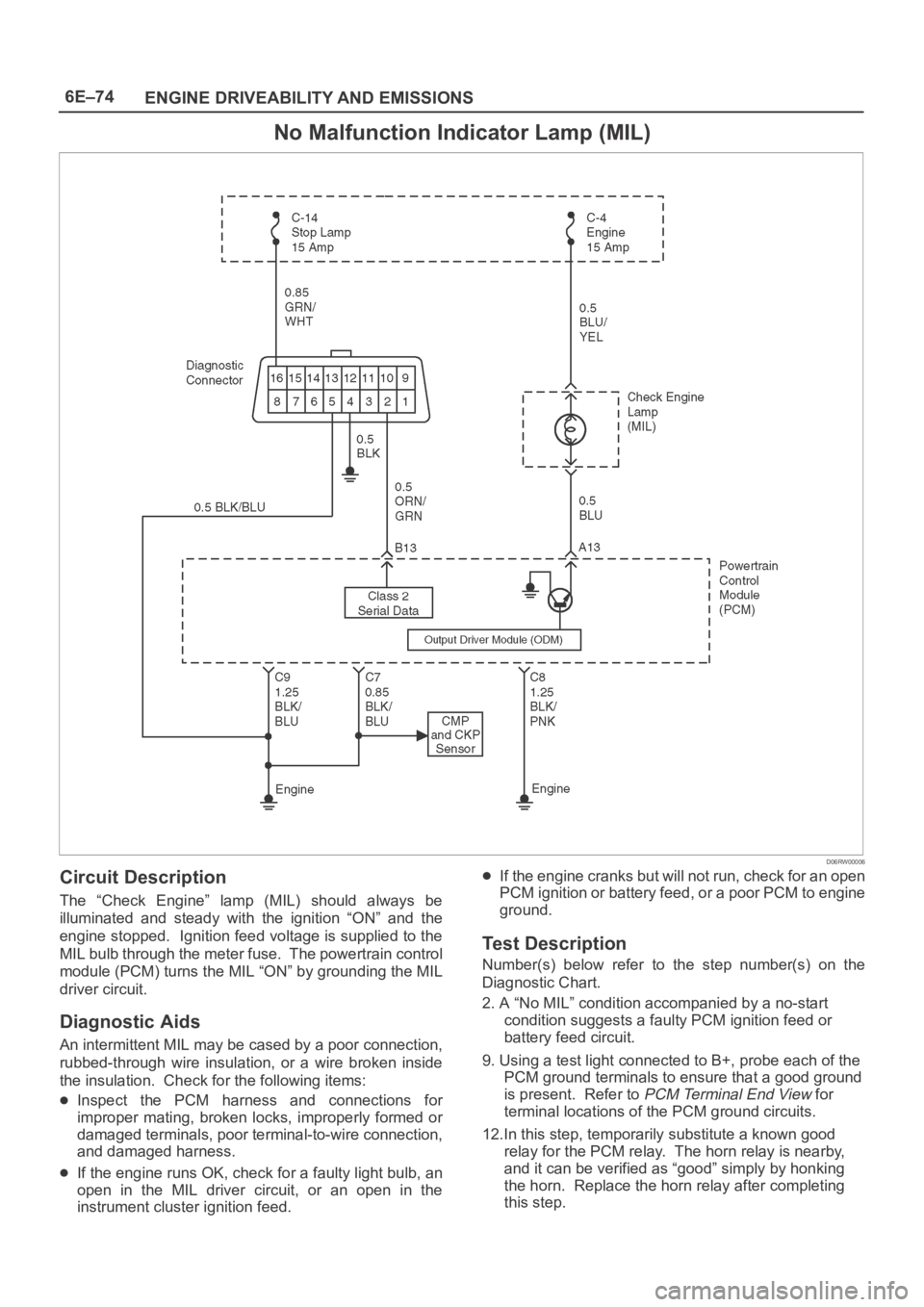
No Malfunction Indicator Lamp (MIL)
D06RW00006
Circuit Description
The “Check Engine” lamp (MIL) should always be
illuminated and steady with the ignition “ON” and the
engine stopped. Ignition feed voltage is supplied to the
MIL bulb through the meter fuse. The powertrain control
module (PCM) turns the MIL “ON” by grounding the MIL
driver circuit.
Diagnostic Aids
An intermittent MIL may be cased by a poor connection,
rubbed-through wire insulation, or a wire broken inside
the insulation. Check for the following items:
Inspect the PCM harness and connections for
improper mating, broken locks, improperly formed or
damaged terminals, poor terminal-to-wire connection,
and damaged harness.
If the engine runs OK, check for a faulty light bulb, an
open in the MIL driver circuit, or an open in the
instrument cluster ignition feed.
If the engine cranks but will not run, check for an open
PCM ignition or battery feed, or a poor PCM to engine
ground.
Test Description
Number(s) below refer to the step number(s) on the
Diagnostic Chart.
2. A “No MIL” condition accompanied by a no-start
condition suggests a faulty PCM ignition feed or
battery feed circuit.
9. Using a test light connected to B+, probe each of the
PCM ground terminals to ensure that a good ground
is present. Refer to
PCM Terminal End View for
terminal locations of the PCM ground circuits.
12.In this step, temporarily substitute a known good
relay for the PCM relay. The horn relay is nearby,
and it can be verified as “good” simply by honking
the horn. Replace the horn relay after completing
this step.
Page 4732 of 6000
6E–75 ENGINE DRIVEABILITY AND EMISSIONS
17.This vehicle is equipped with a PCM which utilizes
an electrically erasable programmable read only
memory (EEPROM). When the PCM is replaced,
the new PCM must be programmed. Refer to
UBS
98 model year Immobilizer Workshop Manual.
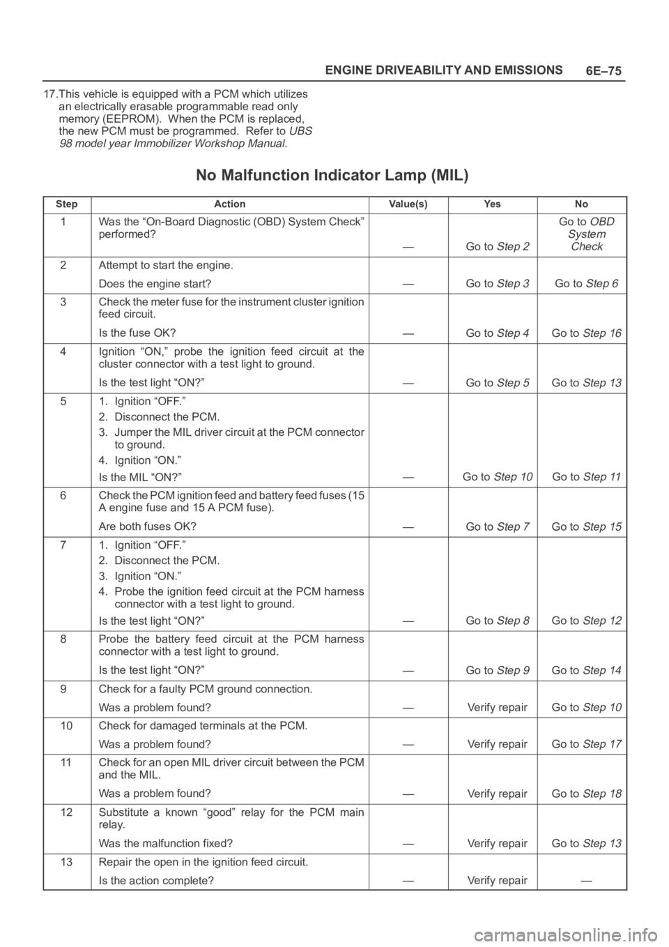
No Malfunction Indicator Lamp (MIL)
StepActionVa l u e ( s )Ye sNo
1Was the “On-Board Diagnostic (OBD) System Check”
performed?
—Go to Step 2
Go to OBD
System
Check
2Attempt to start the engine.
Does the engine start?
—Go to Step 3Go to Step 6
3Check the meter fuse for the instrument cluster ignition
feed circuit.
Is the fuse OK?
—Go to Step 4Go to Step 16
4Ignition “ON,” probe the ignition feed circuit at the
cluster connector with a test light to ground.
Is the test light “ON?”
—Go to Step 5Go to Step 13
51. Ignition “OFF.”
2. Disconnect the PCM.
3. Jumper the MIL driver circuit at the PCM connector
to ground.
4. Ignition “ON.”
Is the MIL “ON?”
—Go to Step 10Go to Step 11
6Check the PCM ignition feed and battery feed fuses (15
A engine fuse and 15 A PCM fuse).
Are both fuses OK?
—Go to Step 7Go to Step 15
71. Ignition “OFF.”
2. Disconnect the PCM.
3. Ignition “ON.”
4. Probe the ignition feed circuit at the PCM harness
connector with a test light to ground.
Is the test light “ON?”
—Go to Step 8Go to Step 12
8Probe the battery feed circuit at the PCM harness
connector with a test light to ground.
Is the test light “ON?”
—Go to Step 9Go to Step 14
9Check for a faulty PCM ground connection.
Was a problem found?
—Verify repairGo to Step 10
10Check for damaged terminals at the PCM.
Was a problem found?
—Verify repairGo to Step 17
11Check for an open MIL driver circuit between the PCM
and the MIL.
Was a problem found?
—Verify repairGo to Step 18
12Substitute a known “good” relay for the PCM main
relay.
Was the malfunction fixed?
—Verify repairGo to Step 13
13Repair the open in the ignition feed circuit.
Is the action complete?
—Verify repair—
Page 4733 of 6000
6E–76
ENGINE DRIVEABILITY AND EMISSIONS
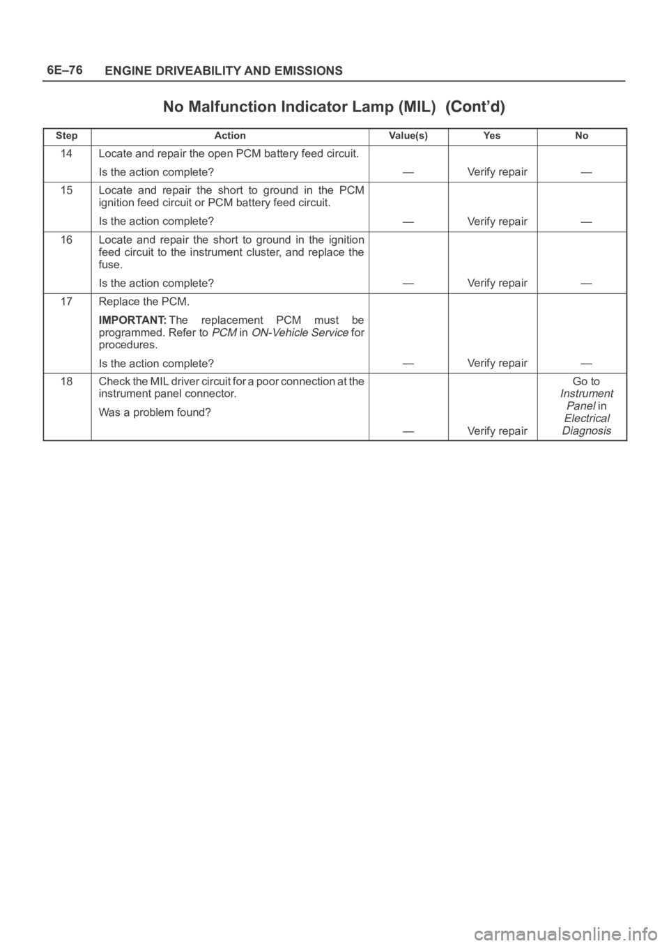
No Malfunction Indicator Lamp (MIL)
StepNo Ye s Va l u e ( s ) Action
14Locate and repair the open PCM battery feed circuit.
Is the action complete?
—Verify repair—
15Locate and repair the short to ground in the PCM
ignition feed circuit or PCM battery feed circuit.
Is the action complete?
—Verify repair—
16Locate and repair the short to ground in the ignition
feed circuit to the instrument cluster, and replace the
fuse.
Is the action complete?
—Verify repair—
17Replace the PCM.
IMPORTANT:The replacement PCM must be
programmed. Refer to
PCM in ON-Vehicle Service for
procedures.
Is the action complete?
—Verify repair—
18Check the MIL driver circuit for a poor connection at the
instrument panel connector.
Was a problem found?
—Verify repair
Go to
Instrument
Panel
in
Electrical
Diagnosis
Page 4738 of 6000

6E–81 ENGINE DRIVEABILITY AND EMISSIONS
Engine Cranks But Will Not Run
StepActionVa l u e ( s )Ye sNo
1Was the “On-Board Diagnostic (OBD) System Check”
performed?
—Go to Step 2
Go to OBD
System
Check
2Check the 15 A ignition coil fuse, the 15 A engine fuse,
and the 30 A PCM fuse.
Was a fuse blown?
—Go to Step 3Go to Step 4
3Check for a short to ground and replace the fuse.
Is the action complete?
—Verify repair—
41. Ignition “OFF,” install a fuel pressure gauge at the
test fitting on the fuel supply line in the engine
compartment. (Use a shop cloth to absorb any fuel
leakage while making the connection.)
2. Ignition “ON,” observe the fuel pressure.
Is the fuel pressure within the specified values, and
does it hold steady?
285-376 kPa
(43-55 psi)
Go to Step 6Go to Step 5
5Is any fuel pressure indicated?
—
Go to Fuel
System
Electrical TestGo to Fuel
System
Diagnosis
6Install an injector switch box to the injector test
connector, and attempt to operate the injector.
Did the fuel pressure drop when the injector is
operated?
—Go to Step 7Go to Step 12
7Install an injector test light at the #2 cylinder injector
harness connector.
Does the light blink when the engine is cranked?
—Go to Step 8Go to Step 18
81. Ignition “ON.”
2. While the coil connectors are disconnected, touch
each coil connector’s ignition feed terminal with a
grounded test light (the ignition feed wire is black
with orange tracer).
Did the test light illuminate?
—Go to Step 10Go to Step 9
9Repair the open ignition feed circuit.
Is the action complete?
—Verify repair—
10While the coil connectors are disconnected, touch
each connector’s secondary ground terminal with a
test light to B+. (The ground wires are black.)
Did the test light illuminate at each coil connector?
—Go to Step 12Go to Step 11
11Repair the open secondary ground circuit.
Is the action complete?
—Verify repair—
121. Test the fuel for contamination.
2. If a problem is found, clean the fuel system and
correct the contaminated fuel condition as
necessary. Replace the fuel filter and replace any
injectors that are not delivering fuel (see Injector
Balance Test).
Was a problem found?
—Verify repairGo to Step 13
Page 4744 of 6000

6E–87 ENGINE DRIVEABILITY AND EMISSIONS
Fuel System Electrical Test
StepNo Ye s Va l u e ( s ) Action
9Check for short or open between the PCM and the fuel
pump relay.
Was a problem found?
—Verify repairGo to Step 10
101. Check the fuel pump relay circuit for a poor terminal
connection at the PCM.
2. If a problem is found, replace terminal as necessary.
Was a problem found?
—Verify repairGo to Step 11
11Replace the PCM.
IMPORTANT:The replacement PCM must be
programmed. Refer to
UBS 98model year Immobilizer
Workshop Manual.
Is the action complete?—Verify repair—
121. Reconnect the fuel pump relay.
2. Disconnect the fuel pump electrical connector at the
fuel tank.
3. Using a test light connected to ground, probe the
fuel pump feed wire (harness side).
4. Command the fuel pump “ON” with Tech 2.
Did the light illuminate for 2 seconds?
—Go to Step 15Go to Step 13
131. Honk the horn to verify that the horn relay is
functioning.
2. Substitute the horn relay for the fuel pump relay.
3. Leave the test light connected as in step 12.
4. Command the fuel pump “ON” with Tech 2.
Did the test light illuminate for 2 seconds when the fuel
pump was commanded “ON?”
—Go to Step 17Go to Step 14
141. Re-connect the horn relay in its proper location.
2. Check for a short circuit, blown fuse or open circuit
between the relay and the fuel tank.
Is the action complete?
—Verify repair—
151. With the fuel pump electrical connector at the fuel
tank disconnected, connect a test light between the
feed wire and the ground wire (harness side).
2. Command the fuel pump “ON” with Tech 2.
Did the test light illuminate for 2 seconds?
—Go to Step 18Go to Step 16
16Repair the open circuit in the fuel pump ground wire.
Is the action complete?
—Verify repair—
171. Re-connect the horn relay in its proper location.
2. Replace the fuel pump relay.
Is the action complete?
—Verify repair—
18Replace the fuel pump.
Is the action complete?
—Verify repair—
Page 4746 of 6000
6E–89 ENGINE DRIVEABILITY AND EMISSIONS
The valve or valve seat within the fuel pressure
regulator.
The fuel injector(s).
4. Fuel pressure that drops off during acceleration,
cruise, or hard cornering may case a lean condition.
A lean condition can cause a loss of power, surging,
or misfire. A lean condition can be diagnosed using
a Tech II Tech 2. If an extremely lean condition
occurs, the oxygen sensor(s) will stop toggling. The
oxygen sensor output voltage(s) will drop below 500
mV. Also, the fuel injector pulse width will increase.
IMPORTANT:Make sure the fuel system is not
operating in the “Fuel Cut-Off Mode.”
When the engine is at idle, the manifold pressure is
low (high vacuum). This low pressure (high vacuum)
is applied to the fuel pressure regulator diaphragm.
The low pressure (high vacuum) will offset the
pressure being applied to the fuel pressure regulator
diaphragm by the spring inside the fuel pressure
regulator. When this happens, the result is lower fuel
pressure. The fuel pressure at idle will vary slightly as
the barometric pressure changes, but the fuel
pressure at idle should always be less than the fuel
pressure noted in step 2 with the engine “OFF.”
16.Check the spark plug associated with a particular
fuel injector for fouling or saturation in order to
determine if that particular fuel injector is leaking. If
checking the spark plug associated with a particular
fuel injector for fouling or saturation does not
determine that a particular fuel injector is leaking,
use the following procedure:
Remove the fuel rail, but leave the fuel lines and
injectors connected to the fuel rail. Refer to
Fuel Rail
Assembly
in On-Vehicle Service.
Lift the fuel rail just enough to leave the fuel injector
nozzles in the fuel injector ports.
CAUTION: In order to reduce the risk of fire and
personal injury that may result from fuel spraying on
the engine, verify that the fuel rail is positioned over
the fuel injector ports and verify that the fuel injector
retaining clips are intact.
Pressurize the fuel system by connecting a 10 amp
fused jumper between B+ and the fuel pump relay
connector.
Visually and physically inspect the fuel injector
nozzles for leaks.
17.A rich condition may result from the fuel pressure
being above 376 kPa (55 psi). A rich condition may
cause a DTC P0132 or a DTC P0172 to set.
Driveability conditions associated with rich
conditions can include hard starting (followed by
black smoke) and a strong sulfur smell in the
exhaust.20.This test determines if the high fuel pressure is due
to a restricted fuel return line or if the high fuel
pressure is due to a faulty fuel pressure regulator.
21.A lean condition may result from fuel pressure
below 333 kPa (48 psi). A lean condition may
cause a DTC P0131 or a DTC P0171 to set.
Driveability conditions associated with lean
conditions can include hard starting (when the
engine is cold ), hesitation, poor driveability, lack of
power, surging , and misfiring.
22.Restricting the fuel return line causes the fuel
pressure to rise above the regulated fuel pressure.
Command the fuel pump “ON” with Tech 2. The fuel
pressure should rise above 376 kPa (55 psi) as the
fuel return line becomes partially closed.
NOTE: Do not allow the fuel pressure to exceed 414 kPa
( 6 0 p s i ) . F u e l p r e s s u r e i n e x c e s s o f 4 1 4 k P a ( 6 0 p s i ) m a y
damage the fuel pressure regulator.
CAUTION: To reduce the risk of fire and personal
injury:
It is necessary to relieve fuel system pressure
before connecting a fuel pressure gauge. Refer to
Fuel Pressure Relief Procedure, below.
A small amount of fuel may be released when
disconnecting the fuel lines. Cover fuel line
fittings with a shop towel before disconnecting, to
catch any fuel that may leak out. Place the towel in
an approved container when the disconnect is
completed.
Fuel Pressure Relief Procedure
1. Remove the fuel cap.
2. Remove the fuel pump relay from the underhood
relay center.
3. Start the engine and allow it to stall.
4. Crank the engine for an additional 3 seconds.
Fuel Gauge Installation
1. Remove the shoulder fitting cap.
2. Install fuel gauge 5-8840-0378-0 to the fuel feed line
located in front of and above the right side valve train
cover.
3. Reinstall the fuel pump relay.