air condition OPEL FRONTERA 1998 Repair Manual
[x] Cancel search | Manufacturer: OPEL, Model Year: 1998, Model line: FRONTERA, Model: OPEL FRONTERA 1998Pages: 6000, PDF Size: 97 MB
Page 1006 of 6000
6A–50
ENGINE MECHANICAL
9. Install air conditioner compressor to engine and
tighten to the specified torque.
Torque :
M8 bolts : 22 Nꞏm (2.2 Kgꞏm/16 lb ft)
M10 bolts : 43 Nꞏm (4.4 Kgꞏm/32 lb ft)
10. Install power steering pump, tighten fixing bolt to the
specified torque.
Torque :
M8 bolts : 22Nꞏm (2.2 Kgꞏm/16 lb ft)
M10 bolts : 46 Nꞏm (4.7 Kgꞏm/34 lb ft)
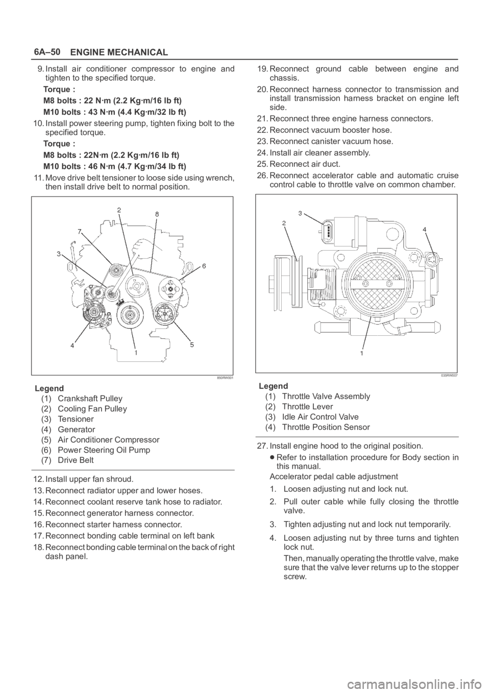
11. Move drive belt tensioner to loose side using wrench,
then install drive belt to normal position.
850RW001
Legend
(1) Crankshaft Pulley
(2) Cooling Fan Pulley
(3) Tensioner
(4) Generator
(5) Air Conditioner Compressor
(6) Power Steering Oil Pump
(7) Drive Belt
12. Install upper fan shroud.
13. Reconnect radiator upper and lower hoses.
14. Reconnect coolant reserve tank hose to radiator.
15. Reconnect generator harness connector.
16. Reconnect starter harness connector.
17. Reconnect bonding cable terminal on left bank
18. Reconnect bonding cable terminal on the back of right
dash panel.19. Reconnect ground cable between engine and
chassis.
20. Reconnect harness connector to transmission and
install transmission harness bracket on engine left
side.
21. Reconnect three engine harness connectors.
22. Reconnect vacuum booster hose.
23. Reconnect canister vacuum hose.
24. Install air cleaner assembly.
25. Reconnect air duct.
26. Reconnect accelerator cable and automatic cruise
control cable to throttle valve on common chamber.
035RW007
Legend
(1) Throttle Valve Assembly
(2) Throttle Lever
(3) Idle Air Control Valve
(4) Throttle Position Sensor
27. Install engine hood to the original position.
Refer to installation procedure for Body section in
this manual.
Accelerator pedal cable adjustment
1. Loosen adjusting nut and lock nut.
2. Pull outer cable while fully closing the throttle
valve.
3. Tighten adjusting nut and lock nut temporarily.
4. Loosen adjusting nut by three turns and tighten
lock nut.
Then, manually operating the throttle valve, make
s u r e t h a t t h e v a l v e l e v e r r e t u r n s u p t o t h e s t o p p e r
screw.
Page 1009 of 6000
6A–53
ENGINE MECHANICAL
2. Remove camshaft bracket fixing bolt (5), camshaft
bracket (6), then camshaft exhaust (7), and intake
side (8).
3. Remove tappet with shim (11).
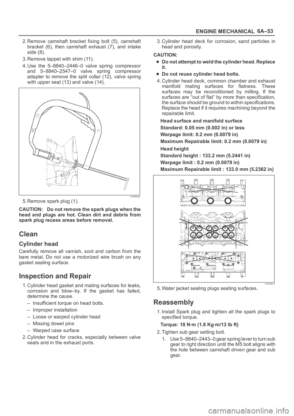
4. Use the 5–8840–2446–0 valve spring compressor
and 5–8840–2547–0 valve spring compressor
adapter to remove the split collar (12), valve spring
with upper seat (13) and valve (14).
014RW042
5. Remove spark plug (1).
CAUTION: Do not remove the spark plugs when the
head and plugs are hot. Clean dirt and debris from
spark plug recess areas before removal.
Clean
Cylinder head
Carefully remove all varnish, soot and carbon from the
bare metal. Do not use a motorized wire brush on any
gasket sealing surface.
Inspection and Repair
1. Cylinder head gasket and mating surfaces for leaks,
corrosion and blow–by. If the gasket has failed,
determine the cause.
– Insufficient torque on head bolts.
– Improper installation
– Loose or warped cylinder head
– Missing dowel pins
– Warped case surface
2. Cylinder head for cracks, especially between valve
seats and in the exhaust ports.3. Cylinder head deck for corrosion, sand particles in
head and porosity.
CAUTION:
Do not attempt to weld the cylinder head. Replace
it.
Do not reuse cylinder head bolts.
4. Cylinder head deck, common chamber and exhaust
manifold mating surfaces for flatness. These
surfaces may be reconditioned by milling. If the
surfaces are “out of flat” by more than specification,
the surface should be ground to within specifications.
Replace the head if it requires machining beyond the
repairable limit.
Head surface and manifold surface
Standard: 0.05 mm (0.002 in) or less
Warpage limit: 0.2 mm (0.0079 in)
Maximum Repairable limit: 0.2 mm (0.0079 in)
Head height
Standard height : 133.2 mm (5.2441 in)
Warpage limit : 0.2 mm (0.0079 in)
Maximum Repairable limit : 133.0 mm (5.2362 in)
011RW019
5. Water jacket sealing plugs seating surfaces.
Reassembly
1. Install Spark plug and tighten all the spark plugs to
specified torque.
Torque: 18 Nꞏm (1.8 Kgꞏm/13 lb ft)
2. Tighten sub gear setting bolt.
1. Use 5–8840–2443–0 gear spring lever to turn sub
gear to right direction until the M5 bolt aligns with
the hole between camshaft driven gear and sub
gear.
Page 1013 of 6000
6A–57
ENGINE MECHANICAL
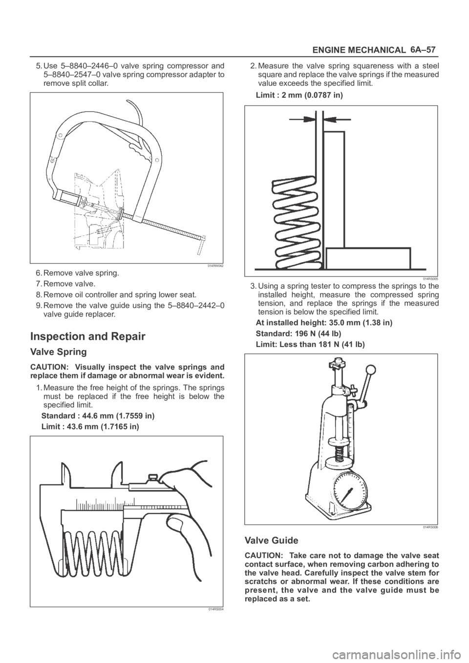
5. Use 5–8840–2446–0 valve spring compressor and
5–8840–2547–0 valve spring compressor adapter to
remove split collar.
014RW042
6. Remove valve spring.
7. Remove valve.
8. Remove oil controller and spring lower seat.
9. Remove the valve guide using the 5–8840–2442–0
valve guide replacer.
Inspection and Repair
Valve Spring
CAUTION: Visually inspect the valve springs and
replace them if damage or abnormal wear is evident.
1. Measure the free height of the springs. The springs
must be replaced if the free height is below the
specified limit.
Standard : 44.6 mm (1.7559 in)
Limit : 43.6 mm (1.7165 in)
014RS004
2. Measure the valve spring squareness with a steel
square and replace the valve springs if the measured
value exceeds the specified limit.
Limit : 2 mm (0.0787 in)
014RS005
3. Using a spring tester to compress the springs to the
installed height, measure the compressed spring
tension, and replace the springs if the measured
tension is below the specified limit.
At installed height: 35.0 mm (1.38 in)
Standard: 196 N (44 lb)
Limit: Less than 181 N (41 lb)
014RS006
Valve Guide
CAUTION: Take care not to damage the valve seat
contact surface, when removing carbon adhering to
the valve head. Carefully inspect the valve stem for
scratchs or abnormal wear. If these conditions are
present, the valve and the valve guide must be
replaced as a set.
Page 1034 of 6000
6A–78
ENGINE MECHANICAL
015RS031
Remove any ridge or carbon build up from the top
end of the cylinder.
9. Remove the piston rings (8) with a piston ring
expander. Arrange the removed piston rings in the
cylinder number order.
015RS022
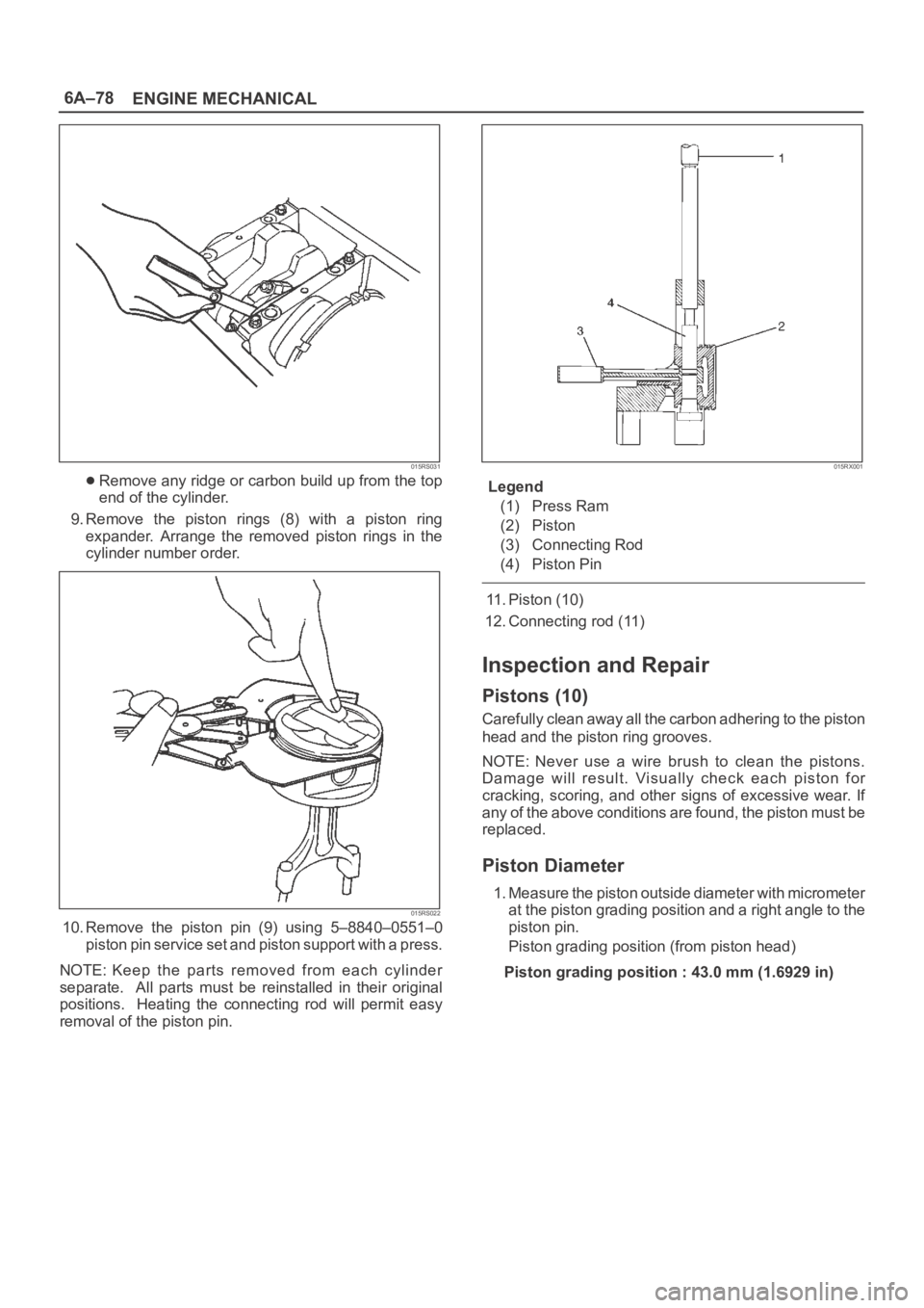
10. Remove the piston pin (9) using 5–8840–0551–0
piston pin service set and piston support with a press.
NOTE: Keep the parts removed from each cylinder
separate. All parts must be reinstalled in their original
positions. Heating the connecting rod will permit easy
removal of the piston pin.
015RX001
Legend
(1) Press Ram
(2) Piston
(3) Connecting Rod
(4) Piston Pin
11. Piston (10)
12. Connecting rod (11)
Inspection and Repair
Pistons (10)
Carefully clean away all the carbon adhering to the piston
head and the piston ring grooves.
NOTE: Never use a wire brush to clean the pistons.
Damage will result. Visually check each piston for
cracking, scoring, and other signs of excessive wear. If
any of the above conditions are found, the piston must be
replaced.
Piston Diameter
1. Measure the piston outside diameter with micrometer
at the piston grading position and a right angle to the
piston pin.
Piston grading position (from piston head)
Piston grading position : 43.0 mm (1.6929 in)
Page 1058 of 6000
ENGINE COOLING6B–5
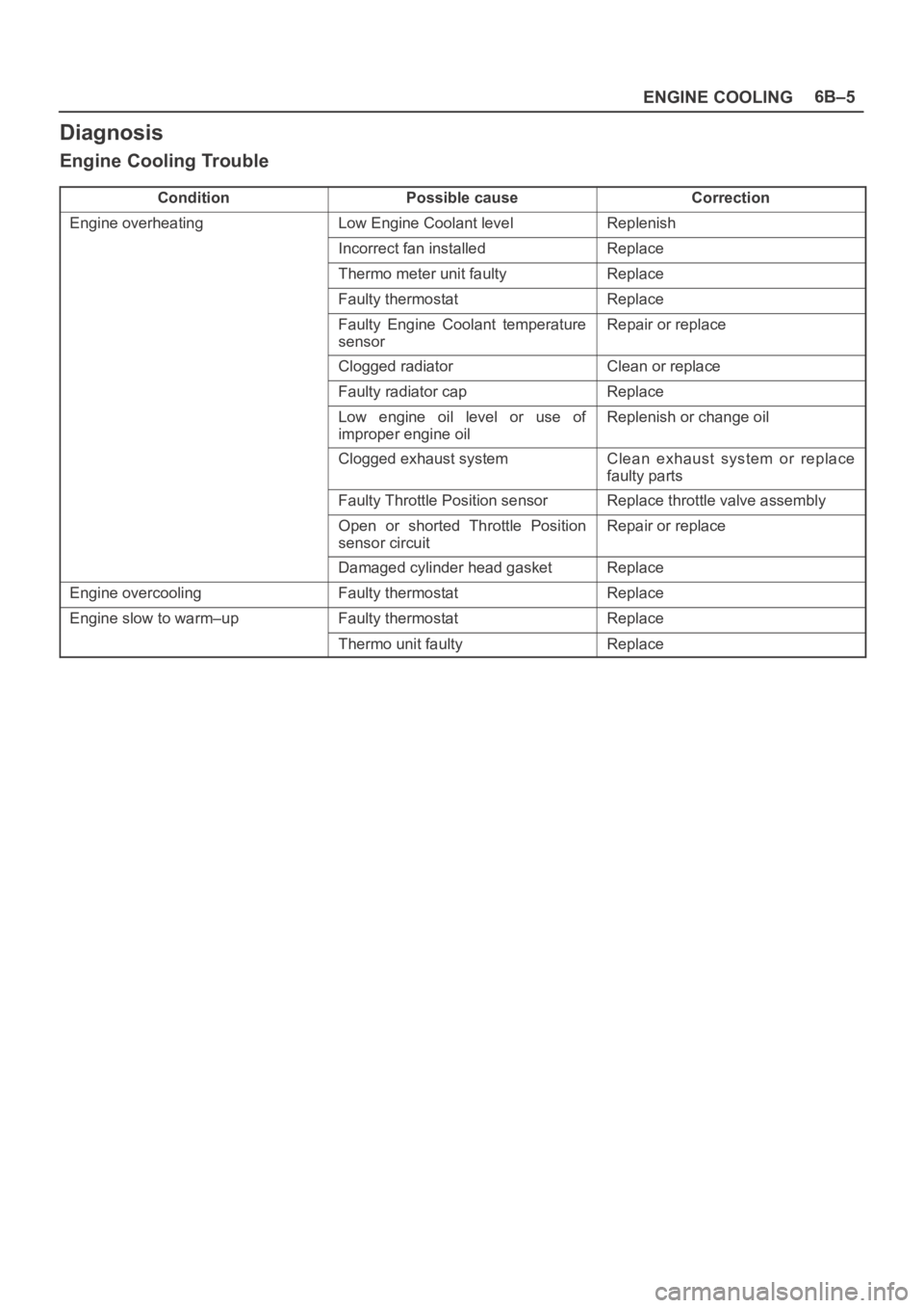
Diagnosis
Engine Cooling Trouble
ConditionPossible causeCorrection
Engine overheatingLow Engine Coolant levelReplenish
Incorrect fan installedReplace
Thermo meter unit faultyReplace
Faulty thermostatReplace
Faulty Engine Coolant temperature
sensorRepair or replace
Clogged radiatorClean or replace
Faulty radiator capReplace
Low engine oil level or use of
improper engine oilReplenish or change oil
Clogged exhaust systemClean exhaust system or replace
faulty parts
Faulty Throttle Position sensorReplace throttle valve assembly
Open or shorted Throttle Position
sensor circuitRepair or replace
Damaged cylinder head gasketReplace
Engine overcoolingFaulty thermostatReplace
Engine slow to warm–upFaulty thermostatReplace
Thermo unit faultyReplace
Page 1063 of 6000
6B–10
ENGINE COOLING
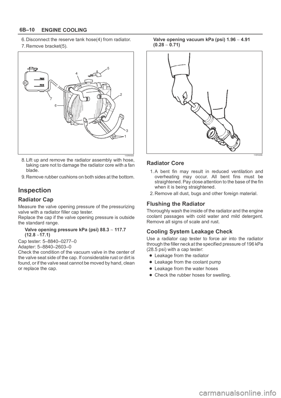
6. Disconnect the reserve tank hose(4) from radiator.
7. Remove bracket(5).
110RW004
8. Lift up and remove the radiator assembly with hose,
taking care not to damage the radiator core with a fan
blade.
9. Remove rubber cushions on both sides at the bottom.
Inspection
Radiator Cap
Measure the valve opening pressure of the pressurizing
valve with a radiator filler cap tester.
Replace the cap if the valve opening pressure is outside
the standard range.
Valve opening pressure kPa (psi) 88.3
117.7
(12.8
17.1)
Cap tester: 5–8840–0277–0
Adapter: 5–8840–2603–0
Check the condition of the vacuum valve in the center of
the valve seat side of the cap. If considerable rust or dirt is
found, or if the valve seat cannot be moved by hand, clean
or replace the cap.Valve opening vacuum kPa (psi) 1.96
4.91
(0.28
0.71)
110RS006
Radiator Core
1. A bent fin may result in reduced ventilation and
overheating may occur. All bent fins must be
straightened. Pay close attention to the base of the fin
when it is being straightened.
2. Remove all dust, bugs and other foreign material.
Flushing the Radiator
Thoroughly wash the inside of the radiator and the engine
coolant passages with cold water and mild detergent.
Remove all signs of scale and rust.
Cooling System Leakage Check
Use a radiator cap tester to force air into the radiator
through the filler neck at the specified pressure of 196 kPa
(28.5 psi) with a cap tester:
Leakage from the radiator
Leakage from the coolant pump
Leakage from the water hoses
Check the rubber hoses for swelling.
Page 1065 of 6000

6B–12
ENGINE COOLING
Drive Belt and Cooling Fan
Drive Belt and Associated Parts
015RW005
Legend
(1) Crankshaft Pulley
(2) Generator
(3) Power Steering Pump(4) Water Pump and Cooling Fan Pulley
(5) Idle Pulley
(6) Tension Pulley
(7) Drive Belt
The drive belt adjustment is not required as automatic
drive belt tensioner is equipped.
Inspection
Check drive belt for wear or damage, and replace with a
new one as necessary.
Installation
Install cooling fan assembly and tighten bolts/nuts to the
specified torque.
Torque : 22 Nꞏm (2.2 Kgꞏm/16 lb ft) for fan pulley
and fan bracket.
Torque : 10 Nꞏm (1.0 Kgꞏm/88.5 lb in) for fan and
clutch assembly.
NOTE: Fan belts for 6VE1 Gasoline Engine mounted on
98MY (UX) have been brought into one. As a result, the
rotating direction of a fan belt is opposite to the direction
o f c o o l i n g f a n f o r 9 2 t o 9 7 M Y 6 V D 1 w i t h n o
interchangeability.
Therefore, incorrect installation of a fan may cause the air
for cooling to flow in the opposite direction, this resulting
in the poor performance of the air-conditioner and a rise
temperature in engine cooling water.
Page 1070 of 6000
6C–3
ENGINE FUEL
Adhere to all Notices and Cautions.
All gasoline engines are designed to use only unleaded
gasoline. Unleaded gasoline must be used for proper
emission control system operation.
Its use will also minimize spark plug fouling and extend
engine oil life. Using leaded gasoline can damage the
emission control system and could result in loss of
emission warranty coverage.
All cars are equipped with an Evaporative Emission
Control System. The purpose of the system is to minimize
the escape of fuel vapors to the atmosphere.
Fuel Metering
The Engine Control Module (ECM) is in complete control
of this fuel delivery system during normal driving
conditions.
The intake manifold function, like that of a diesel, is used
only to let air into the engine. The fuel is injected by
separate injectors that are mounted over the intake
manifold.
The Manifold Absolute Pressure (MAP) sensor measures
the changes in the intake manifold pressure which result
from engine load and speed changes, which the MAP
sensor converts to a voltage output.
This sensor generates the voltage to change
corresponding to the flow of the air drawn into the engine.
The changing voltage is transformed into an electric
signal and provided to the ECM.
With receipt of the signals sent from the MAP sensor,
Intake Air Temperature sensor and others, the ECM
determines an appropriate fuel injection pulse width
feeding such information to the fuel injector valves to
effect an appropriate air/fuel ratio.
The Multiport Fuel Injection system utilizes an injection
system where the injectors turn on at every crankshaft
re vol u tion . Th e EC M con tro ls t he in je cto r on tim e so t ha t
the correct amount of fuel is metered depending on
driving conditions.
Two interchangeable “O” rings are used on the injector
that must be replaced when the injectors are removed.
The fuel rail is attached to the top of the intake manifold
and supplies fuel to all the injectors.
Fuel is recirculated through the rail continually while the
engine is running. This removes air and vapors from the
fuel as well as keeping the fuel cool during hot weather
operation.
The fuel pressure control valve that is mounted on the fuel
rail maintains a pressure differential across the injectors
under all operating conditions. It is accomplished by
controlling the amount of fuel that is recirculated back to
the fuel tank based on engine demand.
See Section “Driveability and Emission” for more
information and diagnosis.
Page 1083 of 6000

6D1–4
ENGINE ELECTRICAL
4. Attach one end of the remaining cable to the negative
terminal of the booster battery.
Attach the other end of the same cable to a solid
engine ground (such as the air conditioning
compressor bracket or the generator mounting
bracket) of the vehicle with the discharged battery.
The ground connection must be at least 450 mm (18
in.) from the battery of the vehicle whose battery is
being charged.
WARNING: NEVER ATTACH THE END OF THE
JUMPER CABLE DIRECTLY TO THE NEGATIVE
TERMINAL OF THE DEAD BATTERY.
5. Start the engine of the vehicle with the good battery.
Make sure that all unnecessary electrical accessories
have been turned “OFF”.
6. Start the engine of the vehicle with the dead battery.
7. To remove the jumper cables, follow the above
directions in reverse order.
Be sure to first disconnect the negative cable from the
vehicle with the discharged battery.
Battery Removal
061RS002
1. Remove negative cable (1).
2. Remove positive cable (2).
3. Remove retainer screw and rods (3).
4. Remove retainer (4).
5. Remove battery (5).
Battery Installation
1. Install battery (5).
2. Install retainer (4).
3. Instal retainer screw and rods (3).
NOTE: Make sure that the rod is hooked on the body
side.
4. Install positive cable (2).
5. Install negative cable (1).
Page 1095 of 6000
6D3–4STARTING AND CHARGING SYSTEM
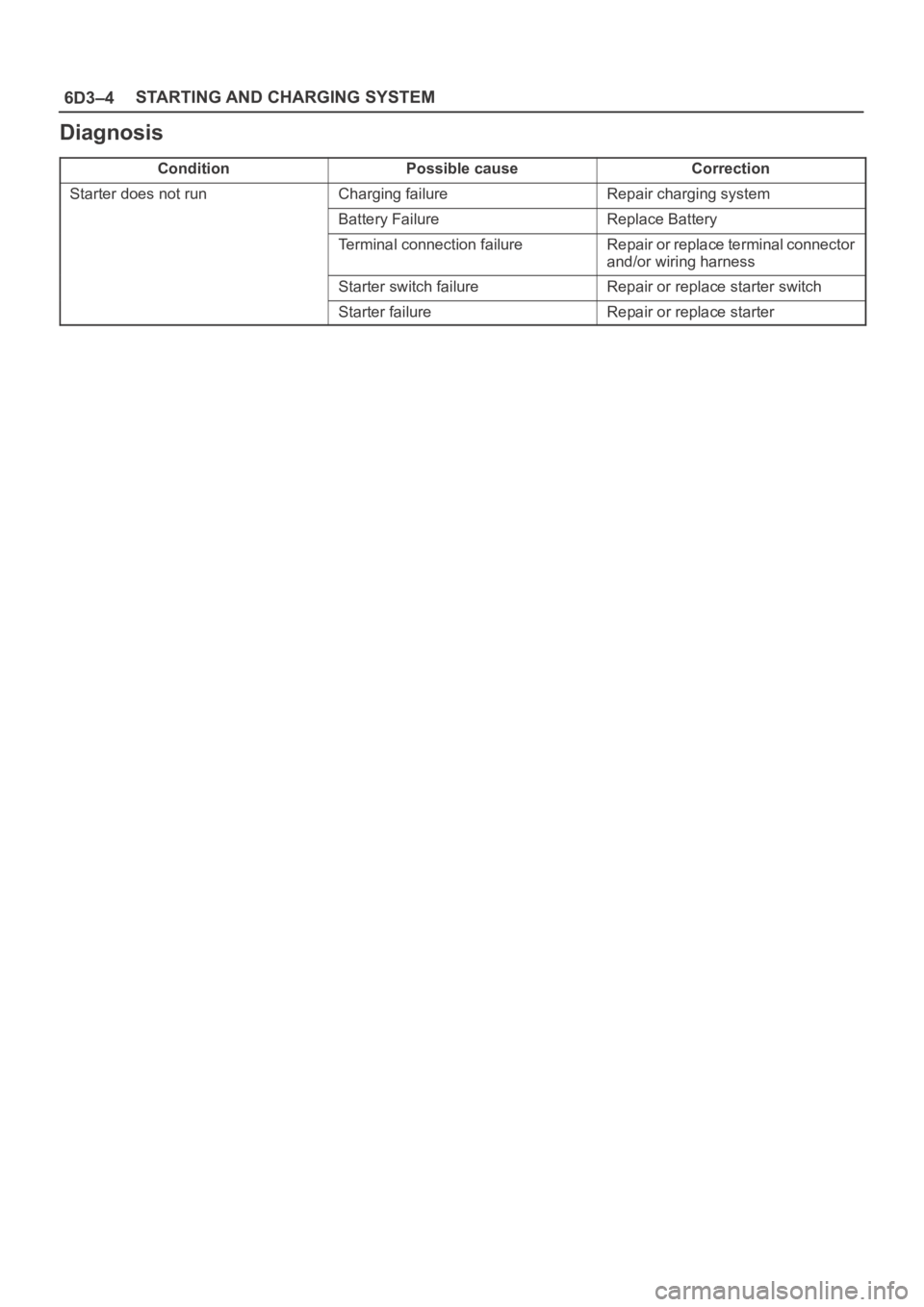
Diagnosis
ConditionPossible causeCorrection
Starter does not runCharging failureRepair charging system
Battery FailureReplace Battery
Terminal connection failureRepair or replace terminal connector
and/or wiring harness
Starter switch failureRepair or replace starter switch
Starter failureRepair or replace starter