radiator OPEL FRONTERA 1998 Manual PDF
[x] Cancel search | Manufacturer: OPEL, Model Year: 1998, Model line: FRONTERA, Model: OPEL FRONTERA 1998Pages: 6000, PDF Size: 97 MB
Page 4599 of 6000

6B–6
ENGINE COOLING
Draining and Refilling Cooling
System
Before draining the cooling system, inspect the system
and perform any necessary service to ensure that it is
clean, does not leak and is in proper working order. The
engine coolant (EC) level should be between the “MIN”
and “MAX” lines of reserve tank when the engine is cold.
If low, check for leakage and add EC up to the “MAX” line.
There should not be any excessive deposit of rust or
scales around the radiator cap or radiator filler hole, and
the EC should also be free from oil.
Replace the EC if excessively dirty.
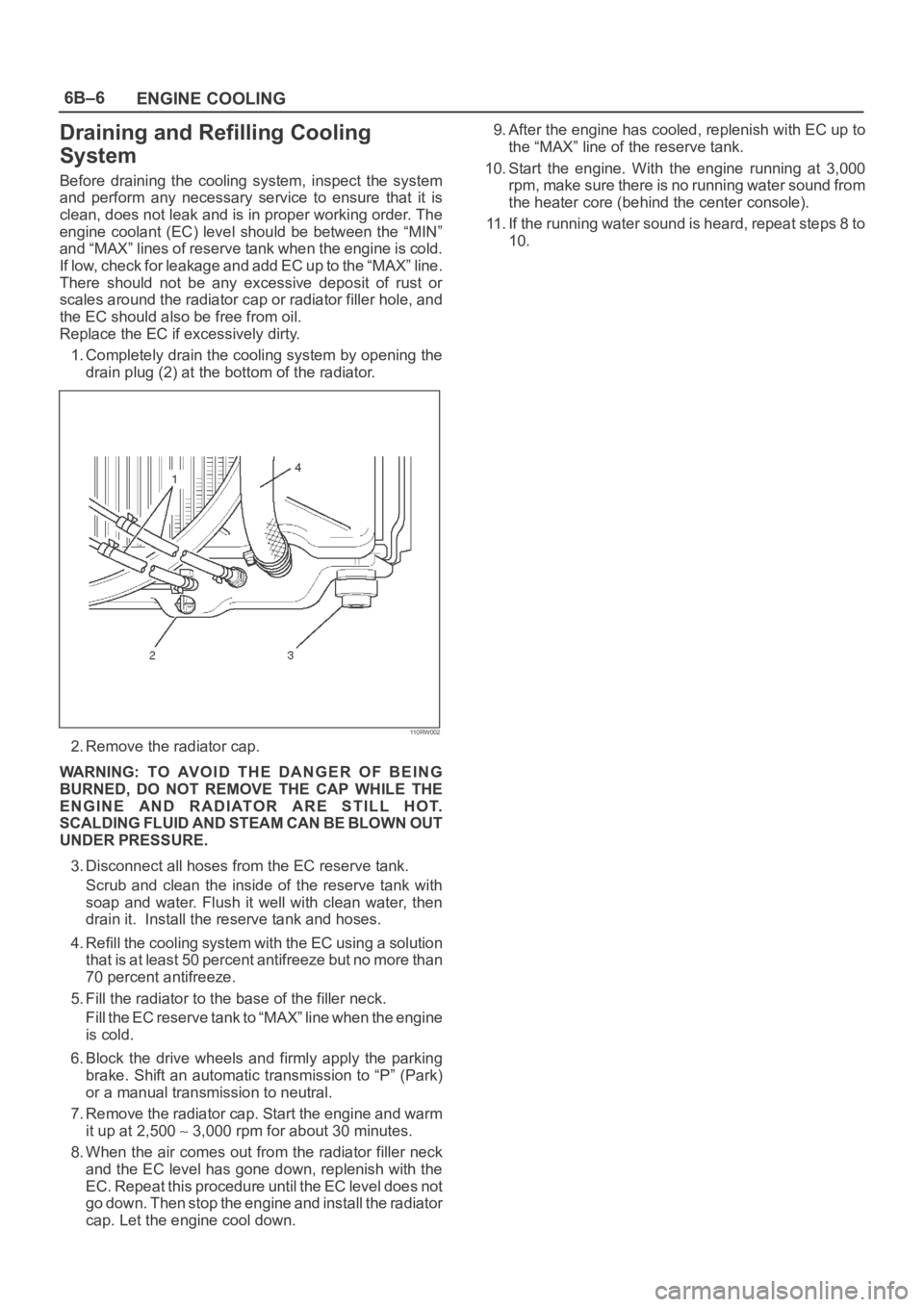
1. Completely drain the cooling system by opening the
drain plug (2) at the bottom of the radiator.
110RW002
2. Remove the radiator cap.
WARNING: TO AVOID THE DANGER OF BEING
BURNED, DO NOT REMOVE THE CAP WHILE THE
ENGINE AND RADIATOR ARE STILL HOT.
SCALDING FLUID AND STEAM CAN BE BLOWN OUT
UNDER PRESSURE.
3. Disconnect all hoses from the EC reserve tank.
Scrub and clean the inside of the reserve tank with
soap and water. Flush it well with clean water, then
drain it. Install the reserve tank and hoses.
4. Refill the cooling system with the EC using a solution
that is at least 50 percent antifreeze but no more than
70 percent antifreeze.
5. Fill the radiator to the base of the filler neck.
Fill the EC reserve tank to “MAX” line when the engine
is cold.
6. Block the drive wheels and firmly apply the parking
brake. Shift an automatic transmission to “P” (Park)
or a manual transmission to neutral.
7. Remove the radiator cap. Start the engine and warm
it up at 2,500
3,000 rpm for about 30 minutes.
8. When the air comes out from the radiator filler neck
and the EC level has gone down, replenish with the
EC. Repeat this procedure until the EC level does not
go down. Then stop the engine and install the radiator
cap. Let the engine cool down.9. After the engine has cooled, replenish with EC up to
the “MAX” line of the reserve tank.
10. Start the engine. With the engine running at 3,000
rpm, make sure there is no running water sound from
the heater core (behind the center console).
11. If the running water sound is heard, repeat steps 8 to
10.
Page 4600 of 6000

ENGINE COOLING6B–7
Water Pump
Water Pump and Associated Parts
030RS002
Legend
(1) Timing Belt
(2) Idle Pulley(3) Water Pump Assembly
(4) Gasket
Removal
1. Disconnect battery ground cable.
2. Drain coolant.
3. Radiator hose (on inlet pipe side).
4. Remove timing belt. Refer to “Timing Belt” in this
manual.
5. Remove Idle pulley.
6. Remove water pump assembly.
7. Remove gasket.
Inspection
Make necessary repair and parts replacement if extreme
wear or damage is found during inspection. Should any of
the following problems occur, the entire water pump
assembly must be replaced:
Crack in the water pump body
EC leakage from the seal unit
Play or abnormal noise in the bearing
Cracks or corrosion in the impeller.
Installation
1. Install gasket, clean the mating surface of gasket
before installation.2. Install water pump assembly and tighten bolts to the
specified torque.
Torque: 25 Nꞏm (2.5 Kgꞏm/18 lb ft)
Tightening order
The tightening order are in the illustrate.
NOTE: To prevent the oil leakage, apply the LOCTITE
262 or an equivalent, to the arrow marked fixing bolt
thread.
030RW008
Page 4601 of 6000

6B–8
ENGINE COOLING
3. Idle pulley
Install idle pulley and tighten bolt to the specified
torque.
Torque: 52 Nꞏm (5.3 Kgꞏm/38 lb ft)4. Timing beltInstall timing belt. Refer to timing belt installation
step in “Timing Belt” in this manual.
5. Connect radiator inlet hose and replenish EC.
6. Connect battery ground cable.
Thermostat
Thermostat and Associated Parts
031RW001
Legend
(1) Thermostat Housing
(2) Thermostat
(3) Outlet Pipe
Removal
1. Disconnect battery ground cable.
2. Drain engine coolant from the radiator and engine.
3. Disconnect radiator hose from the inlet pipe.
4. Remove thermostat housing.
5. Remove thermostat(2).
Inspection
Suspend the thermostat in a water–filled container using
thin wire. Place a thermometer next to the thermostat.
Do not directly heat the thermostat.
Gradually increase the water temperature. Stir the water
so that the entire water is same temperature.
031RS003Confirm the temperature when the valve first begins to
open.
Valve opening temperature 74.5C
78.5C
(166.1
F 173.3F)
Confirm the temperature when the valve is fully opened.
Valve full open temperature and lift More than
8.5mm (0.33 in) at 90
C (194F)
Make necessary repair and parts replacement if extreme
wear or damage is found during inspection.
Installation
1. Install thermostat into the outlet pipe(4) making sure
that the air hole is in the up position.
2. Install thermostat housing and tighten bolts to the
specified torque.
Torque: 25 Nꞏm (2.5 Kgꞏm/18 lb ft)
3. Installation rubber hose.
4. Replenish engine coolant (EC).
5. Start engine and check for EC leakage.
Page 4602 of 6000

ENGINE COOLING6B–9
Radiator
Radiator and Associated Parts
110RW003
Legend
(1) Oil Cooler Hose For Automatic Transmission
(2) Radiator Hose
(3) Fan Guide, Lower(4) Reserve Tank Hose
(5) Bracket
(6) Radiator Assembly
(7) Reserve Tank
Removal
1. Disconnect battery ground cable.
2. Loosen a drain plug(2) to drain EC.
3. Disconnect oil cooler hose(1) on automatic
transmission (A/T).
4. Disconnect radiator inlet hose and outlet hose from
the engine.
110RW002
5. Remove fan guide(1), clips(3) on both sides and the
bottom lock, then remove lower fan guide(3) with fan
shroud(4).
110RW001
Page 4603 of 6000

6B–10
ENGINE COOLING
6. Disconnect the reserve tank hose(4) from radiator.
7. Remove bracket(5).
110RW004
8. Lift up and remove the radiator assembly with hose,
taking care not to damage the radiator core with a fan
blade.
9. Remove rubber cushions on both sides at the bottom.
Inspection
Radiator Cap
Measure the valve opening pressure of the pressurizing
valve with a radiator filler cap tester.
Replace the cap if the valve opening pressure is outside
the standard range.
Valve opening pressure kPa (psi) 88.3
117.7
(12.8
17.1)
Cap tester: 5–8840–0277–0
Adapter: 5–8840–2603–0
Check the condition of the vacuum valve in the center of
the valve seat side of the cap. If considerable rust or dirt is
found, or if the valve seat cannot be moved by hand, clean
or replace the cap.Valve opening vacuum kPa (psi) 1.96
4.91
(0.28
0.71)
110RS006
Radiator Core
1. A bent fin may result in reduced ventilation and
overheating may occur. All bent fins must be
straightened. Pay close attention to the base of the fin
when it is being straightened.
2. Remove all dust, bugs and other foreign material.
Flushing the Radiator
Thoroughly wash the inside of the radiator and the engine
coolant passages with cold water and mild detergent.
Remove all signs of scale and rust.
Cooling System Leakage Check
Use a radiator cap tester to force air into the radiator
through the filler neck at the specified pressure of 196 kPa
(28.5 psi) with a cap tester:
Leakage from the radiator
Leakage from the coolant pump
Leakage from the water hoses
Check the rubber hoses for swelling.
Page 4604 of 6000

ENGINE COOLING6B–11
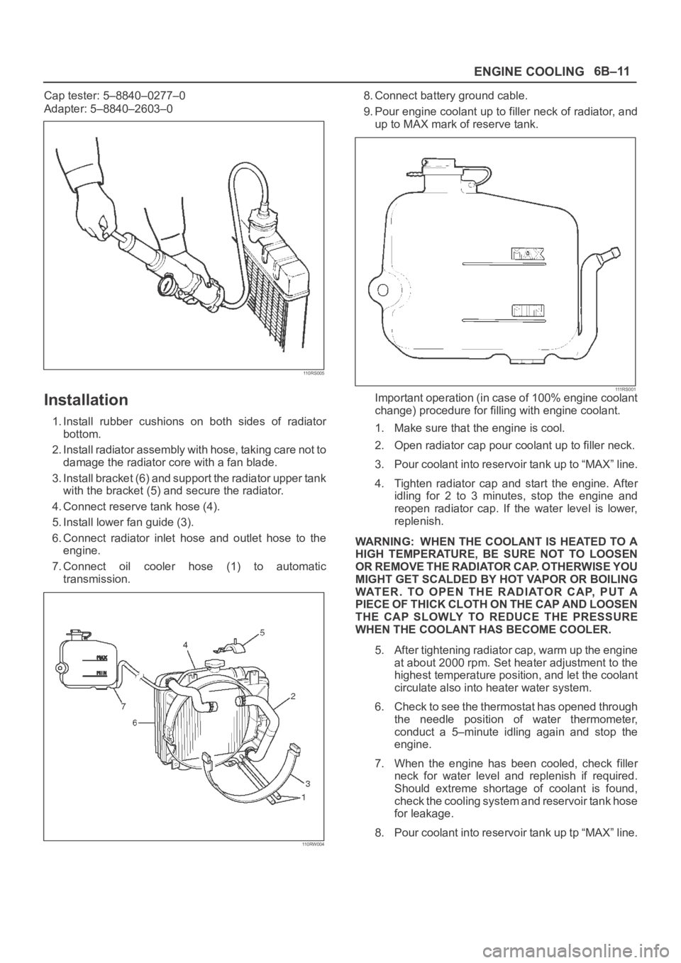
Cap tester: 5–8840–0277–0
Adapter: 5–8840–2603–0
110RS005
Installation
1. Install rubber cushions on both sides of radiator
bottom.
2. Install radiator assembly with hose, taking care not to
damage the radiator core with a fan blade.
3. Install bracket (6) and support the radiator upper tank
with the bracket (5) and secure the radiator.
4. Connect reserve tank hose (4).
5. Install lower fan guide (3).
6. Connect radiator inlet hose and outlet hose to the
engine.
7. Connect oil cooler hose (1) to automatic
transmission.
110RW004
8. Connect battery ground cable.
9. Pour engine coolant up to filler neck of radiator, and
up to MAX mark of reserve tank.
111 R S 0 0 1Important operation (in case of 100% engine coolant
change) procedure for filling with engine coolant.
1. Make sure that the engine is cool.
2. Open radiator cap pour coolant up to filler neck.
3. Pour coolant into reservoir tank up to “MAX” line.
4. Tighten radiator cap and start the engine. After
idling for 2 to 3 minutes, stop the engine and
reopen radiator cap. If the water level is lower,
replenish.
WARNING: WHEN THE COOLANT IS HEATED TO A
HIGH TEMPERATURE, BE SURE NOT TO LOOSEN
OR REMOVE THE RADIATOR CAP. OTHERWISE YOU
MIGHT GET SCALDED BY HOT VAPOR OR BOILING
WATER. TO OPEN THE RADIATOR CAP, PUT A
PIECE OF THICK CLOTH ON THE CAP AND LOOSEN
THE CAP SLOWLY TO REDUCE THE PRESSURE
WHEN THE COOLANT HAS BECOME COOLER.
5. After tightening radiator cap, warm up the engine
at about 2000 rpm. Set heater adjustment to the
highest temperature position, and let the coolant
circulate also into heater water system.
6. Check to see the thermostat has opened through
the needle position of water thermometer,
conduct a 5–minute idling again and stop the
engine.
7. When the engine has been cooled, check filler
neck for water level and replenish if required.
Should extreme shortage of coolant is found,
check the cooling system and reservoir tank hose
for leakage.
8. Pour coolant into reservoir tank up tp “MAX” line.
Page 4606 of 6000

ENGINE COOLING6B–13
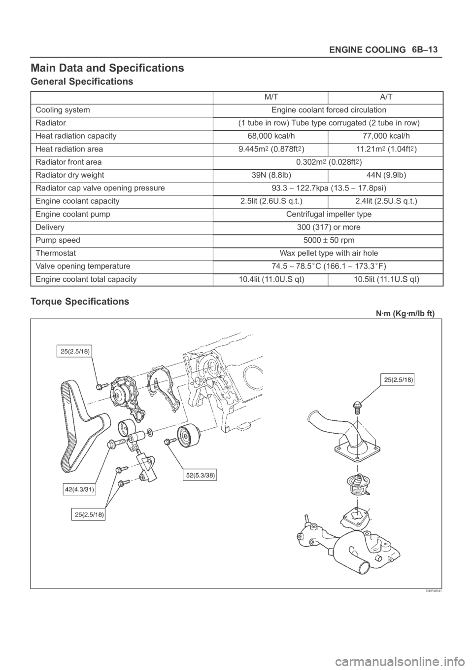
Main Data and Specifications
General Specifications
M/TA/T
Cooling systemEngine coolant forced circulation
Radiator(1 tube in row) Tube type corrugated (2 tube in row)
Heat radiation capacity68,000 kcal/h77,000 kcal/h
Heat radiation area9.445m (0.878ft)11 . 2 1 m (1.04ft)
Radiator front area0.302m (0.028ft)
Radiator dry weight39N (8.8lb)44N (9.9lb)
Radiator cap valve opening pressure93.3 122.7kpa (13.5 17.8psi)
Engine coolant capacity2.5lit (2.6U.S q.t.)2.4lit (2.5U.S q.t.)
Engine coolant pumpCentrifugal impeller type
Delivery300 (317) or more
Pump speed5000 50 rpm
ThermostatWax pellet type with air hole
Valve opening temperature74.5 78.5C (166.1 173.3F)
Engine coolant total capacity10.4lit (11.0U.S qt)10.5lit (11.1U.S qt)
Torque Specifications
Nꞏm (Kgꞏm/lb ft)
E06RW041
Page 4607 of 6000

6B–14
ENGINE COOLING
Special Tool
ILLUSTRATIONTOOL NO.
TOOL NAME
5–8840–0277–0
(J–24460–01)
Tester; radiator cap
5–8840–2603–0
(J–33984–A)
Adapter; radiator cap
Page 4727 of 6000

6E–70
ENGINE DRIVEABILITY AND EMISSIONS
SPARK — Tech 2 Range –64 to 64 —
Displays the amount of spark advance being commanded
by the PCM on the IC circuit.
START-UP ECT — Tech 2 Range –40
C to 151C
(–40
F to 304F) —
Indicates the engine coolant temperature at the time that
the vehicle was started. Used by the HO2S diagnostic to
determine if the last start-up was a cold start.
START-UP IAT — Tech 2 Range –40
C to 151C
(–40
F to 304F) —
Indicates the intake air temperature at the time that the
vehicle was started. Used by the HO2S diagnostic to
determine if the last start-up was a cold start.
TP — Tech 2 Range 0%-100% —
TP (throttle position) angle is computed by the PCM from
the TP sensor voltage. TP angle should display “0%” at
idle and “100%” at wide open throttle.
TP SENSOR — Tech 2 Range 0.00-5.00 Volts —
The voltage being monitored by the PCM on the TP
sensor signal circuit.
CATALYST PROTECTION MODE — Tech 2 Displays
YES or NO —
“YES” displayed indicates that the PCM has detected
conditions appropriate to operate in TWC protection
mode. The PCM will decrease the air/fuel ratio to a value
that depends on mass air flow (higher mass air flow =
lower air/fuel ratio).
UPSHIFT LAMP (MANUAL TRANSMISSION)
VEHICLE SPEED — Tech 2 Range 0-255 km/h
(0-155 mph) —
The vehicle speed sensor signal is converted into km/h
and mph for display.
WEAK CYLINDER — Tech 2 Displays Cylinder
Number —
This indicates that the PCM has detected crankshaft
speed variations that indicate 2% or more cylinder firing
events are misfires.
Typical Scan Data Values
Use the Typical Scan Data Values Table only after the
On-Board Diagnostic System Check has been
completed, no DTC(s) were noted, and you have
determined that the on-board diagnostics are functioning
properly. Tech 2 values from a properly-running engine
may be used for comparison with the engine you are
diagnosing. The typical scan data values represent
values that would be seen on a normally-running engine.
NOTE: A Tech 2 that displays faulty data should not be
used, and the problem should be reported to the Tech 2
manufacturer. Use of a faulty Tech 2 can result in
misdiagnosis and unnecessary replacement of parts.
Only the parameters listed below are referred to in this
service manual for use in diagnosis. For further
information on using the Tech 2 to diagnose the PCM and
related sensors, refer to the applicable reference section
listed below. If all values are within the typical range
described below, refer to the
Symptoms section for
diagnosis.
Test Conditions
Engine running, lower radiator hose hot, transmission in
park or neutral, closed loop, accessaries off, brake not
applied and air conditioning off.
Page 4927 of 6000

6E–270
ENGINE DRIVEABILITY AND EMISSIONS
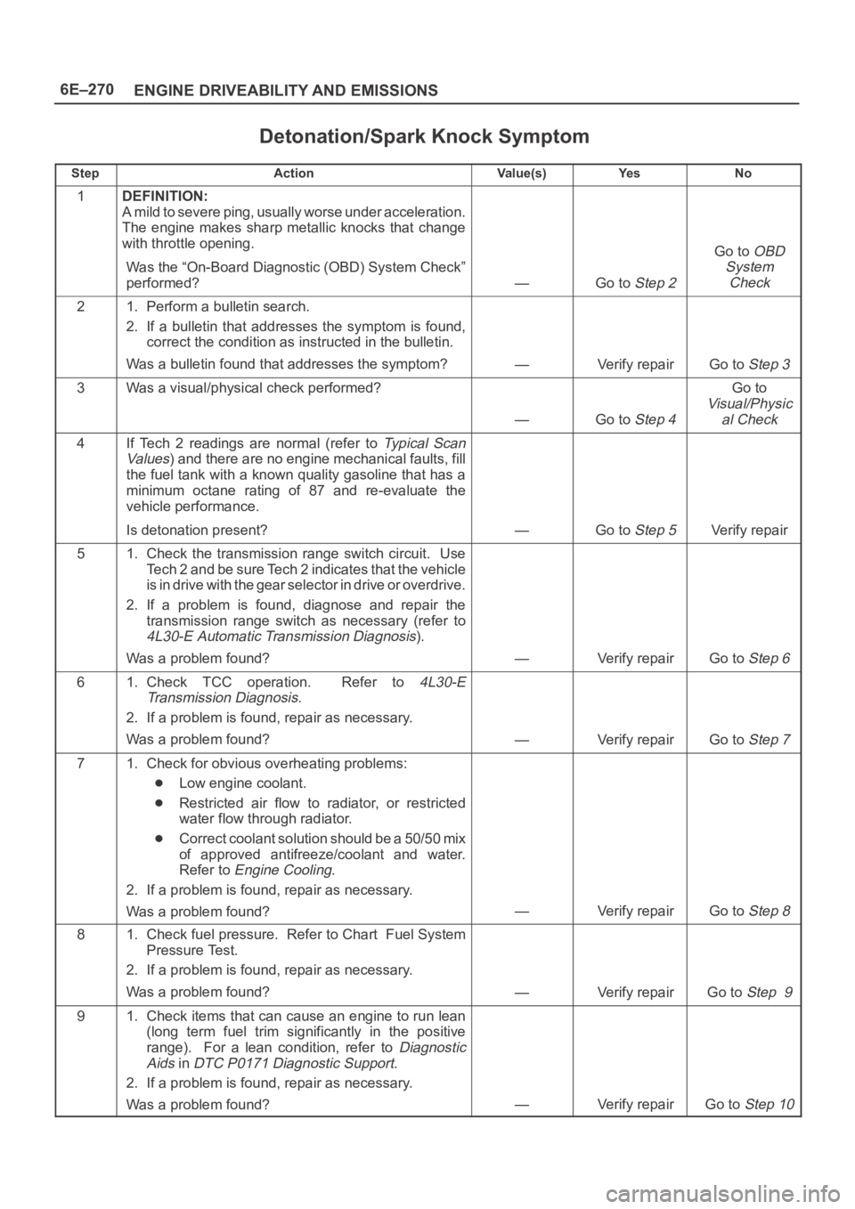
Detonation/Spark Knock Symptom
StepActionVa l u e ( s )Ye sNo
1DEFINITION:
A mild to severe ping, usually worse under acceleration.
The engine makes sharp metallic knocks that change
with throttle opening.
Was the “On-Board Diagnostic (OBD) System Check”
performed?
—Go to Step 2
Go to OBD
System
Check
21. Perform a bulletin search.
2. If a bulletin that addresses the symptom is found,
correct the condition as instructed in the bulletin.
Was a bulletin found that addresses the symptom?
—Verify repairGo to Step 3
3Was a visual/physical check performed?
—Go to Step 4
Go to
Visual/Physic
al Check
4If Tech 2 readings are normal (refer to Ty p i c a l S c a n
Va lu es
) and there are no engine mechanical faults, fill
the fuel tank with a known quality gasoline that has a
minimum octane rating of 87 and re-evaluate the
vehicle performance.
Is detonation present?
—Go to Step 5Verify repair
51. Check the transmission range switch circuit. Use
Tech 2 and be sure Tech 2 indicates that the vehicle
is in drive with the gear selector in drive or overdrive.
2. If a problem is found, diagnose and repair the
transmission range switch as necessary (refer to
4L30-E Automatic Transmission Diagnosis).
Was a problem found?
—Verify repairGo to Step 6
61. Check TCC operation. Refer to 4L30-E
Transmission Diagnosis
.
2. If a problem is found, repair as necessary.
Was a problem found?
—Verify repairGo to Step 7
71. Check for obvious overheating problems:
Low engine coolant.
Restricted air flow to radiator, or restricted
water flow through radiator.
Correct coolant solution should be a 50/50 mix
of approved antifreeze/coolant and water.
Refer to
Engine Cooling.
2. If a problem is found, repair as necessary.
Was a problem found?
—Verify repairGo to Step 8
81. Check fuel pressure. Refer to Chart Fuel System
Pressure Test.
2. If a problem is found, repair as necessary.
Was a problem found?
—Verify repairGo to Step 9
91. Check items that can cause an engine to run lean
(long term fuel trim significantly in the positive
range). For a lean condition, refer to
Diagnostic
Aids
in DTC P0171 Diagnostic Support.
2. If a problem is found, repair as necessary.
Was a problem found?
—Verify repairGo to Step 10