drain bolt OPEL GT-R 1973 Service Manual
[x] Cancel search | Manufacturer: OPEL, Model Year: 1973, Model line: GT-R, Model: OPEL GT-R 1973Pages: 625, PDF Size: 17.22 MB
Page 130 of 625

FRAME AND BODY MOUNTINGS28. 7A
B
C
DE
F
G
H
I
.I
K
L
M
N0
P
Q
R
S112”25-l/4”
22-314”
SO-5/16”
50-5/16”49-l/8”
59-l IS”
35-314”32”36-l/8”
28-19132”
39-118”
15-118”
12-2132”lo-3/4”
6II6”
.l l-5/16”16-l/4”GT FRAME MEASUREMENTS
From centerline of lower ball joint stud to centerline of front lower arm
bushing.
Outside of left frame horn to outside of right frame horn.
Centerline of front crossmember right attaching bolt holes to centerline of front
crossmember left attaching bolt holes.
From centerline of hole in radiator support to right front frame horn
reinforcement to centerline of left front underbody drain hole.
From centerline of hole in radiator support to left front frame horn
reinforcement to centerline of right front underbody drain hole.
From rear outside edge of right front frame rail to rear outside edge of left
front frame rail.
From centerline of lower ball joint stud to centerline of second side drain hole.
Centerline of right lower control arm to centerline of left lower control arm.
Centerline of second side underbody drain hole to centerline of rear spring seat.
Centerline of right spring seat to centerline of left spring seat.
Centerline of spring seat to bumper bracket bolt hole on outside of lower tail
panel.
Outside edge of right rear frame rail to outside edge of left rear frame rail.
Centerline of radiator support bolt hole to centerline of front crossmember front
attaching bolt holes.
Lower edge of front frame horn to datum line.
Frame rail mating surface for front crossmember to datum line.
Front portion of underbody to datum line.
Rear portion of underbody to datum line.
Center of spring seal to datum line.
Centerline of rear bumper bracket to lower tail panel bolt to datum line.
Page 242 of 625
REAR AXLE40- 11
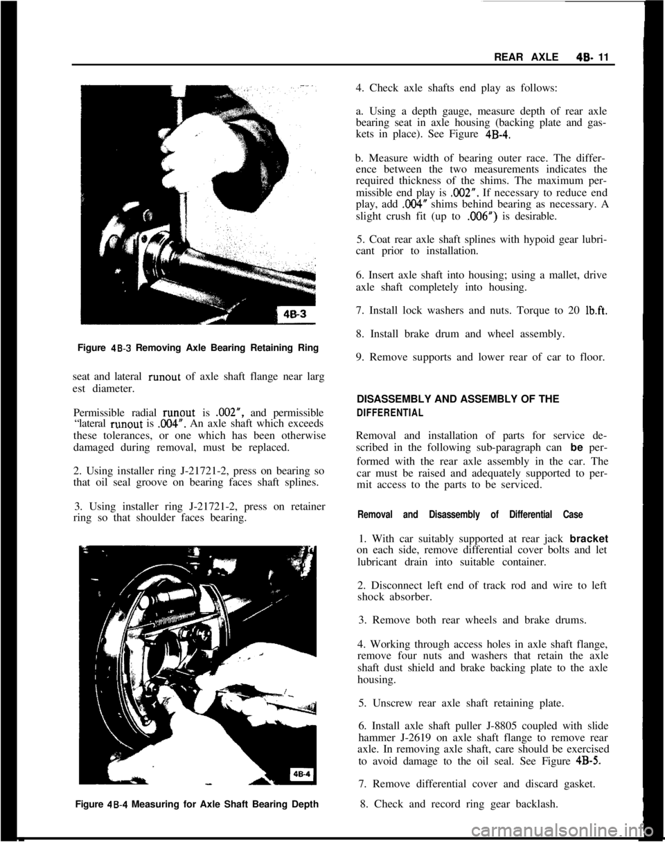
Figure
48-3 Removing Axle Bearing Retaining Ring
seat and lateral runout of axle shaft flange near larg
est diameter.
Permissible radial runout is .002”, and permissible
“lateral runout is
.OO4”. An axle shaft which exceeds
these tolerances, or one which has been otherwise
damaged during removal, must be replaced.
2. Using installer ring J-21721-2, press on bearing so
that oil seal groove on bearing faces shaft splines.
3. Using installer ring J-21721-2, press on retainer
ring so that shoulder faces bearing.
Figure 48.4 Measuring for Axle Shaft Bearing Depth4. Check axle shafts end play as follows:
a. Using a depth gauge, measure depth of rear axle
bearing seat in axle housing (backing plate and gas-
kets in place). See Figure
4B-4.b. Measure width of bearing outer race. The differ-
ence between the two measurements indicates the
required thickness of the shims. The maximum per-
missible end play is .002”. If necessary to reduce end
play, add
,004” shims behind bearing as necessary. A
slight crush fit (up to ,006”) is desirable.
5. Coat rear axle shaft splines with hypoid gear lubri-
cant prior to installation.
6. Insert axle shaft into housing; using a mallet, drive
axle shaft completely into housing.
7. Install lock washers and nuts. Torque to 20
Ib.ft.8. Install brake drum and wheel assembly.
9. Remove supports and lower rear of car to floor.
DISASSEMBLY AND ASSEMBLY OF THE
DIFFERENTIALRemoval and installation of parts for service de-
scribed in the following sub-paragraph can be per-
formed with the rear axle assembly in the car. The
car must be raised and adequately supported to per-
mit access to the parts to be serviced.
Removal and Disassembly of Differential Case1. With car suitably supported at rear jack bracket
on each side, remove differential cover bolts and let
lubricant drain into suitable container.
2. Disconnect left end of track rod and wire to left
shock absorber.
3. Remove both rear wheels and brake drums.
4. Working through access holes in axle shaft flange,
remove four nuts and washers that retain the axle
shaft dust shield and brake backing plate to the axle
housing.
5. Unscrew rear axle shaft retaining plate.
6. Install axle shaft puller J-8805 coupled with slide
hammer J-2619 on axle shaft flange to remove rear
axle. In removing axle shaft, care should be exercised
to avoid damage to the oil seal. See Figure
4B-5.7. Remove differential cover and discard gasket.
8. Check and record ring gear backlash.
Page 297 of 625
6A. 61973 OPEL SERVICE MANUALDIAGNOSIS
EXCESSIVE OIL CONSUMPTION
ConditionCorrectionExternal Oil Leaks at:Tighten attaching bolts. If leaks
Rocker Arm Coverspersist, remove cover (or pan),
Crankcase Front Covercheck sealing surfaces for burrs
Oil Pan and Gasketor scoring, replace gasket, and
seal bolts with silastic sealer or
equivalent. Make sure oil level
,is not overfull.
Improper Reading of Dip-Car may not be level when taking r
StickInsuffIcient oil “drain-back” time
after stopping engine (three
minutes must be allowed). Dip-
stick may not be completely pushed
down against stop. Dipstick may
be bent.
Oil Viscosity Too LightUse recommended SAE viscosity for
prevailing temperatures.
Continuous High-SpeedAt speeds above 60 mph, increased
Drivingsumption can be expected with any
Inform customer of this fact.
High-Speed DrivingWhen principal use of automobile i
Following Normal Slowcity driving, crankcase dilution f
Speed City Drivingcondensation occurs. High speed a
temperatures will remove water,
resulting in what appears to be
rapid lowering of oil level.
Inform customer of this fact.
Piston Rings NotAllow engine to accumulate at leas
“Broken In”
4,OCO miles before attempting any
engine disassembly to correct for
oil consumption.
NOISY VALVES AND LIFTERSIf the preceding check indicates valve mechanism is
abnormally noisy, remove the rocker arm cover so
that the various conditions that cause noise may be
The noise level of the valve mechanism cannot bechecked. A piece of heater hose of convenient length
properly judged where the engine is below operatingmay be used to pick out the particular valves or valve
temperature when the hood is raised, or when thelinkages
thit are causing abnormal noise. With the
valve rocker arm covers are removed.engine running at a speed where the noise is pro-
nounced; hold the end of hose to an ear and hold
Before attempting to judge valve noise level, the en-other end about
l/2 inch from point of contact be-
gine must be thoroughly warmed up (at least 20tween rocker arm and valve stem. Mark or record the
minutes of operation at
1200 to 1500 RPM) to stabil-noisy valves for investigation of following causes:ize oil and coolant temperatures and bring all engine
parts to a normal state of expansion. When the
en-1. Sticking, Warped, or Eccentric Valves, Worngine is warmed up, listen for engine noise while
sit-Guides Sticking valves will cause irregular engine
ting in the driver’s seat with the hood closed. Run theoperation or missing on a low speed pull and will
engine at idle and at various higher speeds.usually cause intermittent noise.
Page 299 of 625
6A- 8 1973 OPEL SERVICE MANUAL
Actual adjustment is made by backing off adjusting
nut at the rocker arm until clearance exists between the valve stem, rocker arm, and lifter. Then slowly
tighten adjusting nut until clearance is eliminated.
When clearance is eliminated, turn adjusting nut one
full turn (clockwise). This positions the hydraulic
piston of the hydraulic lifter mid-point in its total
available travel, and no further adjustment is re-
quired.
MAJOR REPAIR
ENGINE ASSEMBLY REMOVAL AND
INSTALLATION
Removal (Opel 1900 and Manta)’
The engine assembly on the Opel 1900 and Manta
can be removed together with the transmission
through the top of the engine compartment.
1. Remove hood (scribe hood hinge to hood mount-
ing location).
2. Disconnect battery negative cable.
3. Drain coolant at lower radiator hose.
4. Remove upper and lower radiator hoses.
5. Remove radiator and fan
shrbud.
6. Disconnect heater hoses.
7. Disconnect brake booster
vacuum hose.
8. Remove air cleaner.
9. Disconnect electrical connections and accelerator
linkage. 10. Remove console.
11. Remove shift lever boot, plate, and shift lever.
12. Raise car on hoist.
13. Disconnect fuel line at pump.
14. Remove front stone shield.
15. Disconnect speedo-cable, back-up light switch,
and clutch cable.
16. Remove drive shaft. I
17. Disconnect exhaust pipe
ar$l bell housing sup-
port.
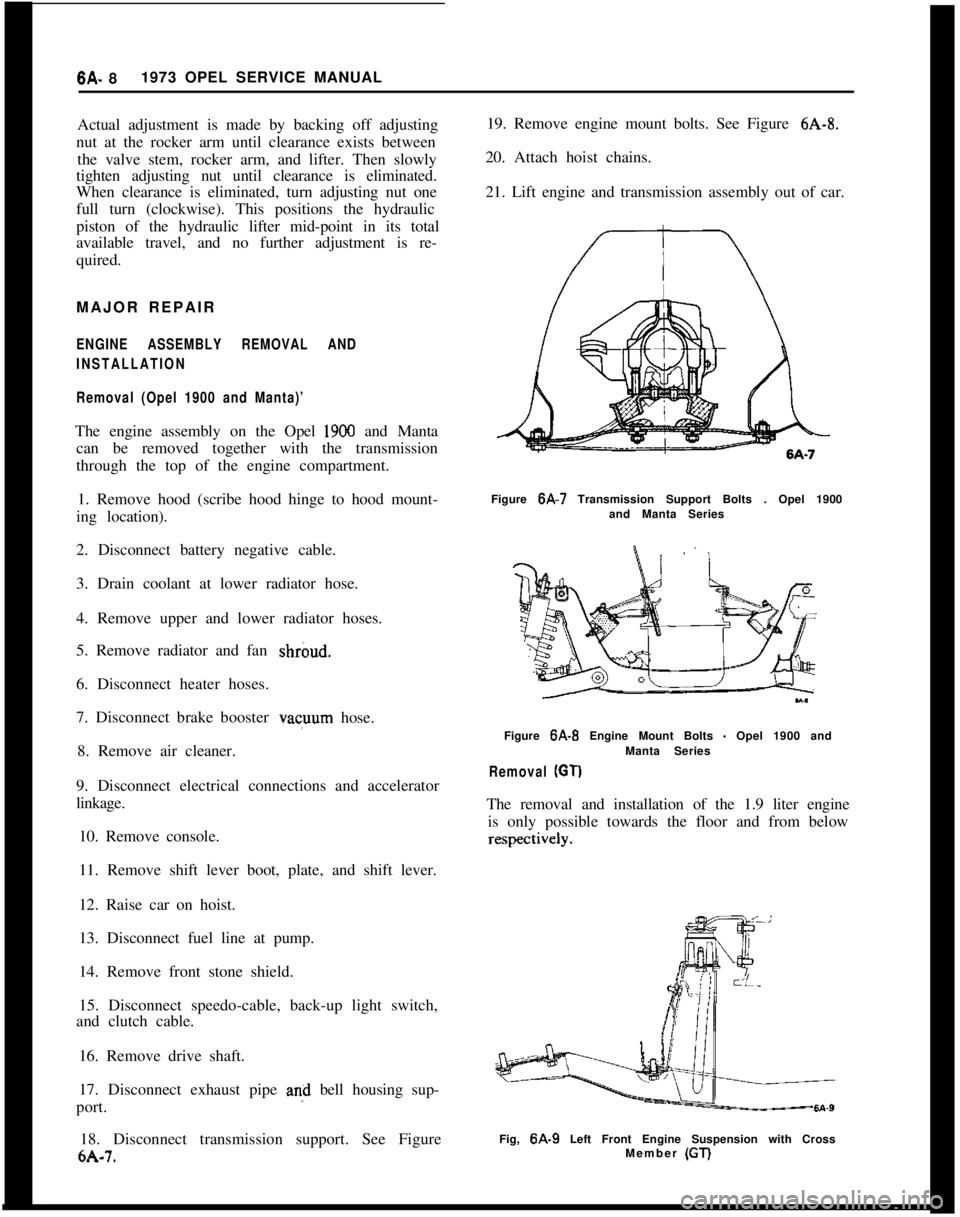
18. Disconnect transmission support. See Figure
6A-7. 19. Remove engine mount bolts. See Figure
6A-8.
20. Attach hoist chains.
21. Lift engine and transmission assembly out of car.
Figure 6A-7 Transmission Support Bolts . Opel 1900
and Manta Series
Figure
6A-B Engine Mount Bolts - Opel 1900 and
Manta Series
Removal (GT)
The removal and installation of the 1.9 liter engine is only possible towards the floor and from below
Fig, 6A-9 Left Front Engine Suspension with Cross
Member (GT)
Page 302 of 625
ENGINE MECHANICAL AND MOUNTS6A- 11
a. Attach left chain to alternator support rear bolt.
b. Bolt right chain to existing threaded hole at lower
right front of engine.
2. Assemble loose ends of chain to support device J-bolts and adjust to remove engine weight from motor
mounts.
3. Remove the two motor mount bracket to motor
mount retaining nuts.
4. Remove the two front suspension to frame rail bolt
retaining nuts.
5. Remove nut and bolt at lower end of steering shaft
U-joint.
6. With a floor jack under the center of the front
suspension cross member, raise car high enough for
wheels and suspension assembly to be rolled from
under car.
7. Position jack stands under both front jack brackets
on underbody to support car in this position.
8. Remove both front cross member support to frame
attaching bolts.
9. Remove brake pipe to brake hose retaining clips
at frame rails and disconnect brake hose from brake
pipes. Use an absorbent material or suitable con-
tainer for the brake fluid that will drain out.
10. Lower the front suspension assembly and remove
from under car.
11. Drain engine oil and remove oil pan and gasket.
Installation (Opel 1900 and Manta)1. Apply a light bead of sealer to the clean sealing
surfaces of the oil pan and affix a new gasket.
2. Bolt oil pan and gasket assembly to engine block.
3. Roll front suspension and floor jack under car and
raise into position careful to pilot the cross member
to frame rail attaching bolts and steering shaft to
their respective locations.
4. Install cross member’support to frame attaching
bolts and torque to 22 lb.ft.
5. Connect brake hose to brake pipes and install
retaining clips.
6. Bleed front brake system. Maintain brake fluid1Wd.
7. Remove jack stands and lower car.8. Install suspension to frame rail bolt retaining nuts.
9. Release and remove engine supporting device.
10. Install motor mount bracket to motor mount
retaining nuts.
11. Install steering shaft U-joint lower bolt and nut.
12. Replace engine oil.
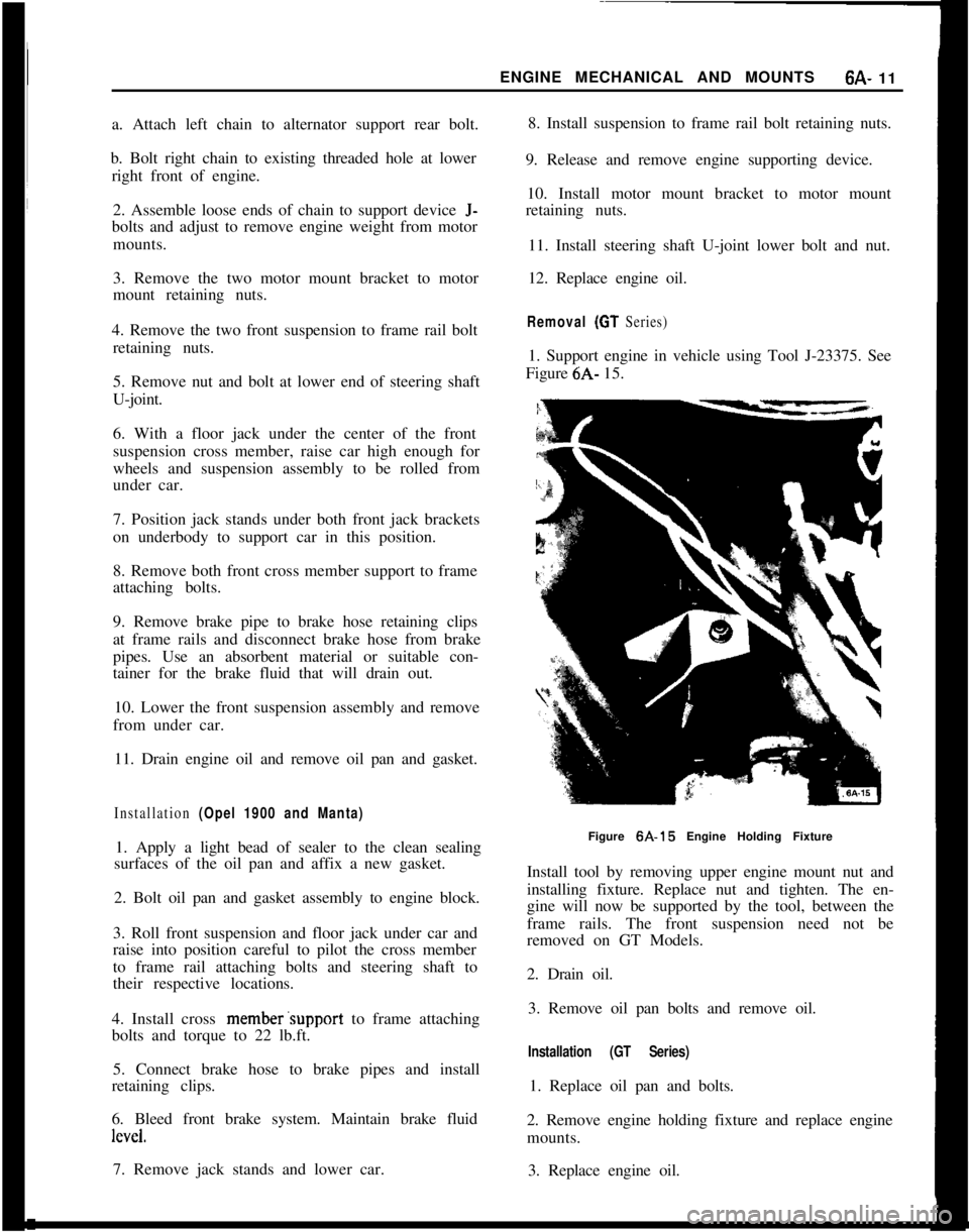
Removal (GT Series)1. Support engine in vehicle using Tool J-23375. See
Figure 6A- 15.
Figure 6A-15 Engine Holding Fixture
Install tool by removing upper engine mount nut and
installing fixture. Replace nut and tighten. The en-
gine will now be supported by the tool, between the
frame rails. The front suspension need not be
removed on GT Models.
2. Drain oil.
3. Remove oil pan bolts and remove oil.
Installation (GT Series)1. Replace oil pan and bolts.
2. Remove engine holding fixture and replace engine
mounts.
3. Replace engine oil.
Page 303 of 625
6A- 121973 OPEL SERVICE MANUALINTAKE AND EXHAUST MANIFOLD REMOVAL
AND
INSTALLATION
Removal1. Disconnect battery.
2. Remove air cleaner.
3. Disconnect throttle linkage at carburetor.
4. Disconnect vacuum advance line at carburetor.
5. Remove fuel line at carburetor inlet.
6. Remove positive crankcase ventilation hose at
rocker arm cover.
7. Disconnect E.G.R. lines from carburetor and in-
take manifold.
8. Disconnect exhaust pipe.
9. Remove six bolts attaching manifold assembly to
cylinder head and remove manifold and carburetor
as an assembly. Discard manifold gasket.
To separate intake and exhaust, manifold, remove
carburetor and four bolts using Tool J-23016, attach-
ing intake manifold to exhaust manifold. Always in-
stall a new manifold intermediate gasket when the
manifolds are separated.
Installation1. Install new manifold gasket and place manifold in
position.
2. Install manifold bolts. New manifold to cylinder
head gasket must be installed whenever a manifold
is removed.
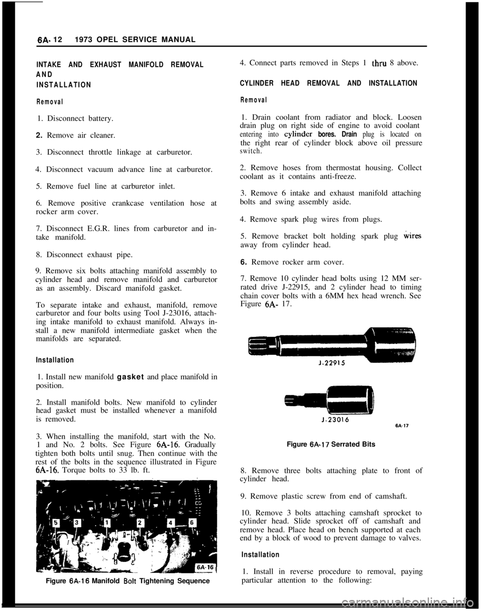
3. When installing the manifold, start with the No.
1 and No. 2 bolts. See Figure 6A-16. Gradually
tighten both bolts until snug. Then continue with the
rest of the bolts in the sequence illustrated in Figure6A-16. Torque bolts to 33 lb. ft.
Figure 6A-16 Manifold
Bolt Tightening Sequence4. Connect parts removed in Steps 1 thru 8 above.
CYLINDER HEAD REMOVAL AND INSTALLATION
Removal1. Drain coolant from radiator and block. Loosen
drain plug on right side of engine to avoid coolant
entering into cylmder bores. Drain plug is located onthe right rear of cylinder block above oil pressure
switch.2. Remove hoses from thermostat housing. Collect
coolant as it contains anti-freeze.
3. Remove 6 intake and exhaust manifold attaching
bolts and swing assembly aside.
4. Remove spark plug wires from plugs.
5. Remove bracket bolt holding spark plug wires
away from cylinder head.
6. Remove rocker arm cover.
7. Remove 10 cylinder head bolts using 12 MM ser-
rated drive J-22915, and 2 cylinder head to timing
chain cover bolts with a 6MM hex head wrench. See
Figure 6A- 17.
Figure 6A-17 Serrated Bits
8. Remove three bolts attaching plate to front of
cylinder head.
9. Remove plastic screw from end of camshaft.
10. Remove 3 bolts attaching camshaft sprocket to
cylinder head. Slide sprocket off of camshaft and
remove head. Place head on bench supported at each
end by a block of wood to prevent damage to valves.
Installation1. Install in reverse procedure to removal, paying
particular attention to the following:
Page 310 of 625
ENGINE MECHANICAL AND MOUNTS6A- 19
sion. When replacing flywheel use new bolts and
torque to 43 lb.ft.
PISTON, RINGS AND CONNECTING RODS
Removal and Disassembly of Piston
and Rod Assemblies
1. Drain oil.
2. Remove oil pan. 3. Remove cylinder head.
4. Examine the cylinder bores above the ring travel.
If bores are worn so a ridge exists, remove the ridges
with a ridge reamer to avoid damaging rings or
cracking ring lands in pistons during removal.
5. Mark the cylinder number on all pistons, connect-
ing rods and caps. Starting at the front end of the
crankcase, the cylinders are numbered l-2-3-4,
6. Remove cap and bearing shell from number 1
connecting rod.
7. Push the piston and
rod assembly up and out of
top cylinder. Then reinstall cap and bearing shell on
rod.
0
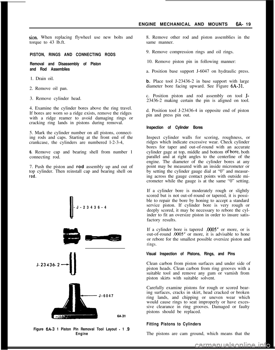
-J-23436-4
J-23436-2+
J-6047
Figure
6A-3 1 Piston Pin Removal Tool Layout - 1 .S
Engine
8. Remove other rod and piston assemblies in the
same manner.
9. Remove compression rings and oil rings.
10. Remove piston pin in following manner:
a. Position base support J-6047 on hydraulic press.
b. Place tool J-23436-2 in base support with large
diameter bore facing upward. See Figure
6A-31.
c. Position piston and rod assembly on tool
J-
23436-2 making certain the pin is aligned on tool.
d. Position tool J-23436-4 in opposite end of piston
pin and press pin out.
Inspection of Cylinder Bores
Inspect cylinder walls for scoring, roughness, or
ridges which indicate excessive wear. Check cylinder
bores for taper and out-of-round with an accurate
cylinder gage at top, middle and bottom
ofbore, both
parallel and at right angles to the centerline of the
engine. The diameter of the cylinder bores at any
point may be measured with an inside micrometer or
by setting the cylinder gauge dial at “0” and measur-
ing across the gauge contact points with outside mi-
crometer while the gauge is at the same “0” setting.
If a cylinder bore is moderately rough or slightly
scored but is not out-of-round or tapered, it is possi-
ble to repair the bore by honing to accept a standard
service piston. If cylinder bore is very rough or deeply scored, it may be necessary to rebore the cyl-
inder to fit an oversize piston in order to insure satis-
factory results.
If a cylinder bore is tapered
.ooO5” or more, or is
out-of-round
.0005” or more, it is advisable to hone
or rebore for the smallest possible oversize piston and
rings.
Visual Inspection of Pistons, Rings, and Pins
Clean carbon from piston surfaces and under side of
piston heads. Clean carbon from ring grooves with a
suitable tool and remove any gum or varnish from
piston skirts with suitable solvent.
Carefully examine pistons for rough or scored bear-
ing surfaces, cracks in skirt, head cracked or broken
ring lands, and chipping or uneven wear which
would cause rings to seat improperly or have exces-
sive clearance in ring grooves. Damaged or faulty
pistons should be replaced.
Fitting Pistons to Cylinders
The pistons are cam ground, which means that the
Page 324 of 625
COOLING SYSTEM6B- 33
remove drain plug on right.side of cylinder block. Set
heater temperature control valve at full heat posi-
tion. After the cooling system is drained, and plugs
reinstalled, fill the system with clean water. Run the
engine long enough to open the thermostat for com-
plete circulation through the system, then com-
pletely drain the cooling system before sediment has
a chance to settle.
Conditioning the Cooling System
“Rust Inhibitor and Stop Leak”, or equivalent listed
under Group 8.800 is recommended for use in the
cooling system, particularly when preparing for in-
stallation of anti-freeze solution. This material stops
small seepage leaks, has rust preventive properties
and its soluble oil is effective in eliminating a squeal-
ing noise which sometimes develops at the water
pump seal washer. Instructions for its application are
printed on the conditioner bottle.
It is very important to make certain that the cooling
system is properly prepared before an anti-freeze so-
lution is installed, otherwise loss of solution through
leakage may occur or seepage may result in damage
to the engine. The cooling system should be drained
and flushed as described under Draining and Flush-
ing Cooling System. All joints should be checked for
leakage and corrected, and the conditioner described
above should be added with the anti-freeze solution.
Inspect the water pump, radiator core, heater and
defroster cores, water jacket plugs, and edge of cylin-
der head gaskets for evidence of water leaks. Tighten
all hose clamps in the cooling and heating systems
and replace any deteriorated hoses.
Using and Testing Anti-Freeze
Solutions
Inhibited year around (ethylene glycol type) engine
coolant solution which is formulated to withstand
two full calendar years of normal operation without
draining or adding inhibitors should be used at all
times. Freeze protection should be provided to pro-
tect against corrosion. When adding solution due to
loss of coolant for any reason or in areas where tem-
peratures lower than minus 20 degrees F. may be
encountered, a sufficient amount of any of the sev-
eral brands of year around coolant (Ethylene Glycol
base) compatible to GM Specification 1899-M avail-
able on the market should be used. Water or alcohol
base coolants are not recommended for this vehicle
at any time.
If for any reason water only is used as a coolant in
an emergency, it is extremely important that Buick
Heavy Duty Cooling System Protector and Water
Pump Lubricant or equivalent be added to the cool-
ing system as soon as possible. If any other cooling
System protector is used, be certain it is labeled toindicate that it meets General Motors Specification
GM 1894-M. It should be recognized that this is only
a temporary measure. The manufacture intends that
permanent type coolant solution be used year around
in the cooling system.
The cooling system should be completely drained
and the recommended coolant installed every two (2)years.It is advisable to test the anti-freeze solution at inter-
vals during the winter to make certain that the solu-
tion has not been weakened. Use only hydrometers
which are calibrated to read both the specific gravity
and the temperature, and have a table or other means
of converting the freezing point at various tempera-
tures of solution. Disregarding the temperature of
the solution when making the test may cause an error
as large as 30 degrees F. Care must be exercised to
use the correct float or table for the particular type
of anti-freeze being tested.
Fan Belt Adjustment or Replacement
A tight fan belt will cause rapid wear of the alterna-
tor and water pump bearings. A loose belt will slip
and wear excessively and will cause noise, engine
over-heating, and unsteady alternator output. A fan
belt which is cracked or frayed, or which is worn so
that it bottoms in the pulleys should be replaced. The
fan belt may be replaced by loosening the alternator
brace at alternator, slightly loosening the alternator
mounting bolts and moving alternator inward to pro-
vide maximum slack in the belt.
The alternator must be moved outward to adjust the
fan belt. After the generator brace and mounting
bolts are securely tightened, the fan belt tension
should be 45 lb. using Tensioner J-23600.
WARNING: Zfa
fan blade is bent or damaged in any
way, no attempt should be made to repair and reuse
the damaged part. A bent or damaged fan assembly
should always be replaced with a new
fal. assembly.
It is essential that fan assemblies remain in proper
balance and proper balance cannot be assured once
a fan assembly has been bent or damaged. A fan
assembly that is not in proper balance could fail and
fly apart during subsequent
we creating an ex-
tremely dangerous condition.
Radiator Thermostat Inspection and Test
A sticking radiator thermostat will prevent the cool-
ing system from functioning properly. If the thermo-
stat sticks in the open position, the engine will warm
up very slowly. If the thermostat sticks in the closed
position, the engine will overheat.
The thermostat may be removed for inspection and
Page 325 of 625
6B- 341973 OPEL SERVICE MANUAL
test by partially draining the cooling system and dis-
connecting the water outlet housing from the ther-
mostat housing which is mounted on the right front
side of cylinder head.
The standard thermostat valve should start to open
at 189 degrees F and fully open at approximately 212
degrees F. If thermostat does not operate at specified
temperatures, it should be replaced as it cannot be
repaired.MAJOR REPAIR
WATER PUMP REPAIRSThe water pump bearing outer race is shrunk fit into
the water pump cover. For this reason the cover,
shaft bearing, and hub are not repairable.
Water Pump RemovalOpel radiators do not have a drain plug. Drain radia-
tor by first, loosening radiator cap, then remove
lower hose from lower radiator tank.
1. Drain coolant into a clean container. Remove
radiator and shroud.
2. Remove fan belt.
3. Remove fan blade and pulley on water pump shaft.
4. Disconnect inlet hose and heater hose from water
pump. Remove bolts, pump assembly and gasket
from timing chain cover.
5. Check pump shaft bearing for end play or rough-
ness in operation. If bearings are not in serviceable
condition, the assembly must be replaced.
Water Pump Installation1. Make sure the gasket surfaces on pump and timing
chain covers are clean. Install pump assembly with
new gasket. Bolts must be tightened uniformly.
Torque to 11 lb. ft.
2. Install radiator and shroud. Connect radiator hose
to pump inlet and heater hose to nipple.
3. Install fan pulley and fan blade, tighten attaching
bolts securely. Install belts and adjust for proper
tension.4. Fill cooling system and check
,for leaks at pump
and hose joints.
RADIATOR REMOVAL AND INSTALLATION
RemovalI. Loosen radiator cap, then remove lower radiator
hose and drain radiator coolant into suitable con-
tainer.
2. On vehicles with automatic transmission, unscrew
oil lines from connectors on lower radiator tank and
plug lines. On GT models with automatic transmis-
sion the lines have to be disconnected at the coupling
before removing from the tank. It is essential that no
dirt enters the oil lines. When unscrewing oil lines,
hold connectors on lower radiator tank with pliers to
avoid leakages. Ensure that no dirt enters oil cooler.
3. Remove lower attaching nut and slide radiator
upward and out of engine compartment.
Installation1. Install radiat,or into engine compartment and se-
cure lower attaching nut.
2. On vehicles with automatic transmissions, fasten
oil cooler lines to lower radiator tank. It is essential
that no dirt enters the oil lines. When tightening oil
lines, hold connectors on lower radiator tank with
pliers to avoid leakages. Ensure that no dirt enters oil
cooler. Torque to 1 I-15
lbs.ft.3. Install lower radiator hose and add collected coo-
lant.
All Opels are provided with a radiator initial fill of
an antifreeze solution containing corrosion inhibitor.
The antifreeze has either a glycol or glycerin base
and protects the engine against freezing, down to
minus 22 degrees F. (minus 30 degrees C.). Before
the start of the cold season, coolant must be checked
with a hydrometer and if necessary, brought to the
necessary specific gravity by adding anti-freeze with
a glycol or glycerin base. As the specific gravities of
all anti- freeze solutions having a glycol or glycerin
base are practically the same, the hydrometer can be
used for all these types. Because of the tolerances of
the hydrometer, or slight differences in specific
gravity, variations of plus or minus 5 degrees can be
expected. Coolant must be checked at a temperature
of plus 68 degrees F. (plus 20 degrees C.)
Page 367 of 625
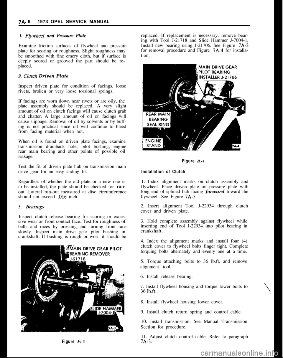
7A- 61973 OPEL SERVICE MANUAL1. FIywheeI and Pressure PlateExamine friction surfaces of flywheel and pressure
plate for scoring or roughness. Slight roughness may
be smoothed with fine emery cloth, but if surface is
deeply scored or grooved the part should be re-
placed.
2.
CJutch Driven Plate
Inspect driven plate for condition of facings, loose
rivets, broken or very loose torsional springs.
If facings are worn down near rivets or are oily, the
plate assembly should be replaced. A very slight
amount of oil on clutch facings will cause clutch grab
and chatter. A large amount of oil on facings will
cause slippage. Removal of oil by solvents or by buff-
ing is not practical since oil will continue to bleed
from facing material when hot.
When oil is found on driven plate facings, examine
transmission drainback hole, pilot bushing, engine
rear main bearing and other points of possible oil
leakage.
Test the fit of driven plate hub on transmission main
drive gear for an easy sliding fit.
Regardless of whether the old plate or a new one is
to be installed, the plate should be checked for run-
out. Lateral run-out measured at disc circumference
should not exceed
.016 inch.
Inspect clutch release bearing for scoring or exces-
sive wear on front contact face. Test for roughness of
balls and races by pressing and turning front race
slowly. Inspect main drive gear pilot bushing in
crankshaft. If bushing is rough or worn it should be
Figure JA-3replaced. If replacement is necessary, remove bear-
ing with Tool J-21718 and Slide Hammer J-7004-1.
Install new bearing using J-21706. See Figure 7A-3
for removal procedure and Figure 7A-4 for installa-
tion.
\,,
Figure JA-4
Installation of Clutch1. Index alignment marks on clutch assembly and
flywheel. Place driven plate on pressure plate with
long end of splined hub facing forward toward the
flywheel. See Figure 7A-5.
2. Insert alignment Tool J-22934 through clutch
cover and driven plate.
3. Hold complete assembly against flywheel while
inserting end of Tool J-22934 into pilot bearing in
crankshaft.
4. Index the alignment marks and install four (4)
clutch cover to flywheel bolts finger tight. Complete
torquing bolts alternately and evenly one at a time.
5. Torque attaching bolts to 36 lb.ft. and remove
alignment tool.
6. Install release bearing.
7. Install flywheel housing and torque lower bolts to
36
lb.ft.8. Install flywheel housing lower cover.
9. Install clutch return spring and control cable.
10. Install transmission. See Manual Transmission
Section for procedure.
11. Adjust clutch control cable. Refer to paragraph7A-3.