washer fluid OPEL GT-R 1973 Service Manual
[x] Cancel search | Manufacturer: OPEL, Model Year: 1973, Model line: GT-R, Model: OPEL GT-R 1973Pages: 625, PDF Size: 17.22 MB
Page 16 of 625
LUBRICATION AND MAINTENANCE OC-7SERVICESLUBE AND GENERAL MAINTENANCE
Vehicle operation under conditions such as heavy
dust, continuous short trips, use of other than un-
leaded or low lead fuels or pulling trailers, is not
considered normal use and therefore more frequent
maintenance will be required. Such additional
maintenance requirements are included where appli-
cable.
Engine OilChange each 4 months or
3,COO miles, whichever
occurs first, or each 2 months or
3,ooO miles when
the vehicle is operated under the following condi-
tions: (a) driving in dusty conditions, (b) trailer pull-
ing, (c) extensive idling or (d) short-trip operation at
freezing temperatures (with engine not thoroughly
warmed-up).Engine oils have a definite effect on ease of starting,
oil economy, combustion chamber deposits and en-
gine wear. It is recommended that a” oil which,
according to the label on the can is; (1) intended for
service SE and (2) passes car makers’ tests be used.
Oils confotming to these types contain detergent ad-
ditives. -
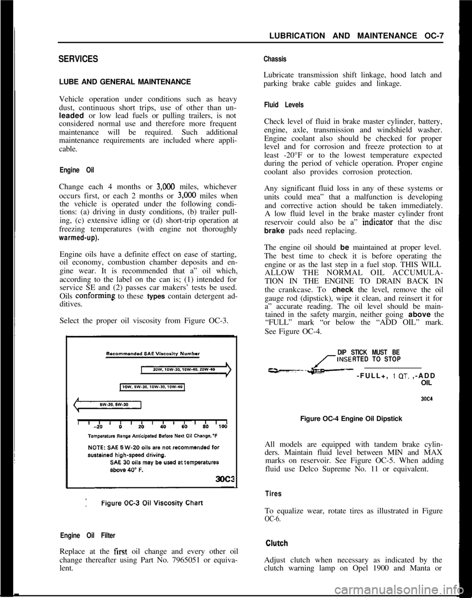
Select the proper oil viscosity from Figure OC-3.
Engine Oil FilterReplace at the first oil change and every other oil
change thereafter using Part No. 7965051 or equiva-
lent.
ChassisLubricate transmission shift linkage, hood latch and
parking brake cable guides and linkage.
Fluid LevelsCheck level of fluid in brake master cylinder, battery,
engine, axle, transmission and windshield washer.
Engine coolant also should be checked for proper
level and for corrosion and freeze protection to at
least -20°F or to the lowest temperature expected
during the period of vehicle operation. Proper engine
coolant also provides corrosion protection.
Any significant fluid loss in any of these systems or
units could mea” that a malfunction is developing
and corrective action should be taken immediately.
A low fluid level in the brake master cylinder front
reservoir could also be a” indtcator that the disc
brake pads need replacing.
The engine oil should be maintained at proper level.
The best time to check it is before operating the
engine or as the last step in a fuel stop. THIS WILL
ALLOW THE NORMAL OIL ACCUMULA-
TION IN THE ENGINE TO DRAIN BACK IN
the crankcase. To check the level, remove the oil
gauge rod (dipstick), wipe it clean, and reinsert it for
a” accurate reading. The oil level should be main-
tained in the safety margin, neither going above the
“FULL” mark “or below the “ADD OIL” mark.
See Figure OC-4.
DIP STICK MUST BE
INSERTED TO STOP
---L- -FULL+, 1 OT. ,-ADD
OIL
Figure OC-4 Engine Oil Dipstick
All models are equipped with tandem brake cylin-
ders. Maintain fluid level between MIN and MAX
marks on reservoir. See Figure OC-5. When adding
fluid use Delco Supreme No. 11 or equivalent.
TiresTo equalize wear, rotate tires as illustrated in Figure
OC-6.Adjust clutch when necessary as indicated by the
clutch warning lamp on Opel 1900 and Manta or
Page 18 of 625
LUBRICATION AND MAINTENANCE OC-9
4. Remove dipstick and wipe clean.
5. Reinsert dipstick untip cap seats.
6. Remove dipstick and note reading.
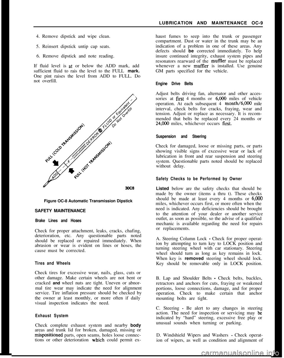
If fluid level is at, or below the ADD mark, add
sufficient fluid to rais the level to the FULL mark.
One pint raises the level from ADD to FULL. Do
not overfill.
3OC8Figure OC-8 Automatic Transmission Dipstick
SAFETY MAINTENANCE
Brake Lines and HosesCheck for proper attachment, leaks, cracks, chafing,
deterioration, etc. Any questionable parts noted
should be replaced or repaired immediately. When
abrasion or wear is evident on lines or hoses, the
cause must be corrected.
Tires and WheelsCheck tires for excessive wear, nails, glass, cuts or
other damage. Make certain wheels are not bent or
cracked and wheel nuts are tight. Uneven or abnor-
mal tire wear may indicate the need for alignment
service. Tire inflation pressure should be checked by
the owner at least monthly, or more often if daily
visual inspection indicates the need.
Exhaust SystemCheck complete exhaust system and nearby body
areas and trunk lid for broken, damaged, missing orm&positioned parts, open seams, holes loose connec-
tions or other deterioration wiuch could permit ex-haust fumes to seep into the trunk or passenger
compartment. Dust or water in the trunk may be an
indication of a problem in one of these areas. Any
defects should be corrected immediately. To help
insure continued integrity, exhaust system pipes and
resonators rearward of the muftler must be replaced
whenever a new mufIler is installed. Use genuine
GM parts specified for the vehicle.
Engine Drive BeltsAdjust belts driving fan, alternator and other acces-
sories at first 4 months or
6,ooO miles of vehicle
operation. At each subsequent 4 month/6,000 mile
interval, check belts for cracks, fraying, wear and
tension. Adjust or replace as necessary. It is recom-
mended that belts be replaced every 24 months or
24,C00 miles, whichever occurs first.
Suspension and SteeringCheck for damaged, loose or missing parts, or parts
showing visible signs of excessive wear or lack of
lubrication in front and rear suspension and steering
system. Questionable parts noted should be replaced
without delay.
Safety Checks to be Performed by OwnerListed below are the safety checks that should be
made by the owner (items a thru t). These checks
should be made at least every 4 months or
6,ooOmiles, whichever occurs first, or more often when the
need is indicated. Any deficiencies should be brought
to the attention of your dealer or another service
outlet, as soon as possible, so the advise of a qualified
mechanic is available regarding the need for repairs
or replacements.
A. Steering Column Lock
_ Check for proper operat-
ion by attempting to turn key to LOCK position and
turning steering wheel with car stationary. Steering
wheel should turn as long as key remains in lock.
When key is removed steering wheel should lock.
Key should be removable only in LOCK position.
B. Lap and Shoulder Belts
- Check belts, buckles,
retractors and anchors for cuts, fraying or weakened
portions, loose connections, damage, and for proper
operation. Check to make certain that anchor
mounting bolts are tight.
C. Steering
- Be alert to any changes in steering
action. The need for inspection or servicing may
beindicated by “hard” steering, excessive free play or
unusual sounds when turning or parking.
D. Windshield Wipers and Washers
- Check operat-
ion of wipers, as well as condition and alignment of
Page 19 of 625
CC-10 1973 OPEL SERVICE MANUAL
wiper blades. Check amount and direction of fluid
sprayed by washers during use.,
E. Defrosters - Check performance by moving con-
trols to “DEF” and noting
am$nmt of air directed
against the windshield.
I
F. Wheel Alignment and
Balabce - In addition to
abnormal tire wear, the need fbr wheel alignment
service may be indicated by a pull to the right or
!eftwhen driving on a straight and level road. The need
for wheel balancing is usually
iddicated by a vibra-
tion of the steering wheel or
se;+ tihile driving at
normal highway speeds.I
IG. Brakes
- Be alert to illumiriation of the brake
warning light or changes in braking action,
SUCK as
repeated pulling to one side, unusual sounds when
braking or increased brake pedal travel. Any of thesecould indicate the need for
brakk system inspection
and/or service.
H. Parking Brake and Transmission “PARK”
Mechanism
- Check parking brake holding ability by
parking on a fairly steep hill and restraining the vehi-
cle with the parking brake only.
eon cars with auto-
matic transmissions, check the holding ability of the
“PARK” mechanism by releasing all brakes after
the transmission selector lever hak been placed in the“P” position.
I. Glass
- Check for broken, scrritched, dirty or da-
maged glass on vehicle that
coulld obscure vision’or
become an injury hazard.
J. Lights and Buzzers
- Check all instrument panel
illuminating and warning lights,’ seat belt reminder
light and buzzer, ignition key
b&er, interior lights,
license plate lights, side marker! lights, headlamps,
parking lamps, tail lamps, brake lights, turn signals,
backup lamps, and hazard warding flashers. Have
someone observe operation of
&ach exterior light
while you activate the controls: The operation of
instrument panel warning lights is covered in the
“Starting and Operating“ section of your
Own&%
Manual.K. Transmission Shift Indicator
‘- Check to be sure
automatic transmission shift
indiCator accurately i”-
dicates the shift position selected.
I
CAUTION: Before making thk check below,I
be sure to have a clear dist&e ahead and:
behind the car, set the parking brake and
firmly apply the foot brake.
Do not depress
accelerator pedal. Be prepared to
turn off ’
ignition switch
immediat+y if engine
should start.L. Starter Safety Switch (Automatic Transmissibn
Cars)
- Check starter safety switch by placing the
transmission in each of the driving gears while
at-tempting to start the engine. The starter should oper-ate only in the Park (“P”) or Neutral (“N”)
positions.
M. Horn
- Blow the horn occasionally to be sure thatit works. (Ignition switch must be in the “ON” posi-
tion.)
N. Seat Back Latches
- Check to see that seat back
latches are holding by pulling forward on the top of
each folding seat back.
0. Rearview Mirrors and Sun Visors
- Check that
friction joints are properly adjusted so mirrors and
sun visors stay in the selected position.
P. Door Latches
- Check for positive closing, latch-
ing and locking.
Q. Hood Latches - Check to make sure hood closesfirmly by pressing on the hood at the latching point
after each closing. Check also for broken, damaged
or missing parts which might prevent secure latch-
ing.R. Fluid Leaks
- Check for fuel, water, oil or other
fluid leaks by observing the ground beneath the vehi-cle after it has been parked for a while. If gasoline
fumes or fluid are noticed at any time, the cause
should be determined and corrected without delay
because of the possibility of fire.
S. Exhaust System
- Be alert to any change in the
sound of the exhaust system or a smell of fumes
which may indicate a leak.
Head Restraints
- Check that no head restraint
components are missing, damaged or loose. (Does
not apply to GT Models).
Disc BrakesCheck brake pads and condition of rotors while
wheels are removed during tire rotation. (Note belowregarding more frequent checks also applies to disc
brakes.)
Parking and Drum BrakesCheck drum
brake linings and other internal brake
components at each wheel (drums, wheel cylinders,
etc.). Parking brake adjustment also should be
checked whenever drum brake linings are checked.
NOTE: More frequent checks should be
made if driving conditions a.nd habits result
in frequent brake application. When brakes
require relining, it is recommended thatyou use those genuine General Motors
parts specified for your car,and Delco fluid
as required.
Page 265 of 625
5A- 61973 OPEL SERVICE MANUAL
ing on dusty and sandy roads - the filter and sound
deadener should occasionally be replaced. To do so,
brake booster has to be removed without detaching
brake master cylinder.
Proceed as follows:
1. Remove protective cap (boot).
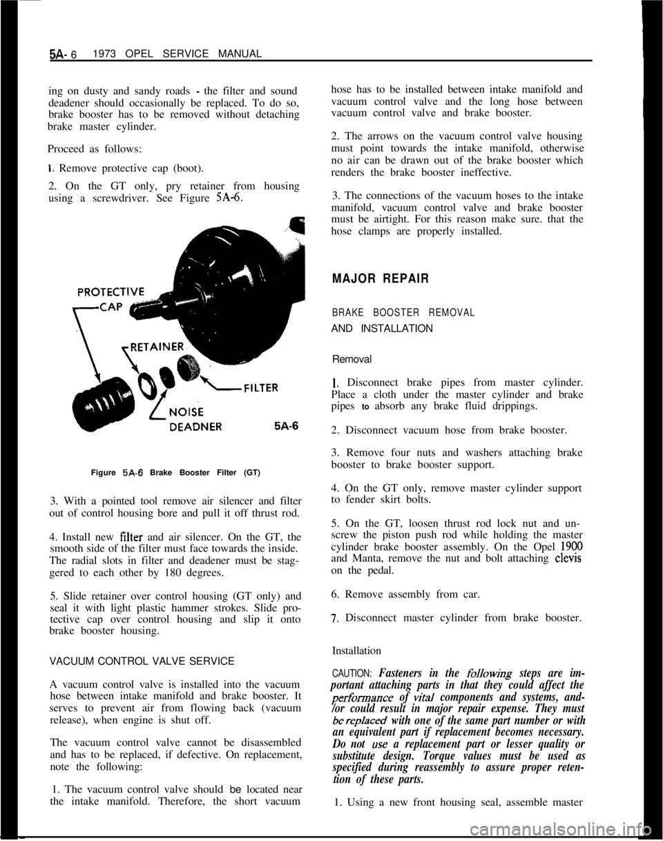
2. On the GT only, pry retainer from housing
using a screwdriver. See Figure
SA-6.Figure 5A-6 Brake Booster Filter (GT)
3. With a pointed tool remove air silencer and filter
out of control housing bore and pull it off thrust rod.
4. Install new filter and air silencer. On the GT, the
smooth side of the filter must face towards the inside.
The radial slots in filter and deadener must be stag-
gered to each other by 180 degrees.
5. Slide retainer over control housing (GT only) and
seal it with light plastic hammer strokes. Slide pro-
tective cap over control housing and slip it onto
brake booster housing.
VACUUM CONTROL VALVE SERVICE
A vacuum control valve is installed into the vacuum
hose between intake manifold and brake booster. It
serves to prevent air from flowing back (vacuum
release), when engine is shut off.
The vacuum control valve cannot be disassembled
and has to be replaced, if defective. On replacement,
note the following:
1. The vacuum control valve should be located near
the intake manifold. Therefore, the short vacuumhose has to be installed between intake manifold and
vacuum control valve and the long hose between
vacuum control valve and brake booster.
2. The arrows on the vacuum control valve housing
must point towards the intake manifold, otherwise
no air can be drawn out of the brake booster which
renders the brake booster ineffective.
3. The connections of the vacuum hoses to the intake
manifold, vacuum control valve and brake booster
must be airtight. For this reason make sure. that the
hose clamps are properly installed.
MAJOR REPAIR
BRAKE BOOSTER REMOVALAND INSTALLATION
Removal
1. Disconnect brake pipes from master cylinder.
Place a cloth under the master cylinder and brake
pipes to absorb any brake fluid drippings.
2. Disconnect vacuum hose from brake booster.
3. Remove four nuts and washers attaching brake
booster to brake booster support.
4. On the GT only, remove master cylinder support
to fender skirt bolts.
5. On the GT, loosen thrust rod lock nut and un-
screw the piston push rod while holding the master
cylinder brake booster assembly. On the Opel
1900and Manta, remove the nut and bolt attaching clevis
on the pedal.
6. Remove assembly from car.
7. Disconnect master cylinder from brake booster.
Installation
CAUTION: Fasteners in the folkwing steps are im-
portant attaching parts in that they could affect the
performance of vital components and systems, and-
/or could result in major repair expense. They must
berep/aced, with one of the same part number or with
an equivalent part if replacement becomes necessary.
Do not
use a replacement part or lesser quality or
substitute design. Torque values must be used as
specified during reassembly to assure proper reten-
tion of these parts.1. Using a new front housing seal, assemble master
Page 266 of 625
POWER BRAKE BOOSTER AND MASTER CYLINDER5A- 7cylinder to brake booster and torque nuts to 14
Ib.ft.on the GT and 12
lb.ft. on the Opel 1900 and Manta.
2. Position assembly into brake booster bracket and,
on the GT only, thread piston push rod onto the
thrust rod.
3. Install brake booster to support attaching washers
and nuts and tighten to 11
lb.ft. of torque.
4. On the GT install master cylinder support to inner
fender skirt bolts.
5. Connect vacuum hose to brake booster.
6. By turning the piston push rod on the thrust rod,
(GT only) adjust until the brake pedal free travel is
l/4 inch and tighten the lock nut.
7. Connect brake pipes to master cylinder and bleed
brakes.
MASTER CYLINDER OVERHAUL. GT
Removal of Master Cylinder1. Disconnect the two brake pipes from the master
cylinder.
2. Remove the front support to skirt attaching bolts,
the cylinder to booster retaining nuts and lift out
master cylinder.
Disassembly1. Prior to brake master cylinder disassembly, pour
brake fluid out of brake fluid reservoir, remove reser-
voir from master cylinder and take sealing plugs out
of housing.
2. Screw static pressure valve(s) out of housing.
3. To facilitate disassembly, push piston somewhat
into cylinder and insert a rounded off piece of weld-
ing rod approx.
.12 in. thick into feed port to retain
piston in this position.
4. Remove stop screw and snap ring out of housing
and take out both pistons together with springs.
5. Remove stop screw from piston for rear brake
circuit and remove all component parts. Remove
also all component parts from intermediate piston of
front brake circuit.
Cleaning and Checking1. Clean parts with genuine brake fluid, Delco Su-
preme No. 11, or equivalent. Do not use any other
cleaning solvents. Dry with compressed air. Free up
compensating and feed ports.2. Polish cylinder bore of housing with crocus cloth.
If lapping scores and rust spots are still noticeable,
replace brake master cylinder assembly.
3. Check inner components for damage and replace,
if required. The rubber seals and static pressure valve
always have to be replaced.
Assembly1. Assemble front and rear brake circuit pistons.
Prior to assembly coat rubber seals with brake fluid.
2. Coat cylinder bore, piston sliding surfaces and
seals with brake fluid.
3. Insert preassembled intermediate piston for front
brake circuit together with thrust spring and spring
seat into clyinder bore. The smaller diameter of the
tapered thrust spring must face piston.
4. With a drift, push piston (against spring pres-
sure) into housing and insert a piece of welding rod
into feed port of front brake circuit to retain piston.
5. Install stop screw with new seal ring into housing
and tighten.
6. Insert preassembled piston for rear brake circuit
into cylinder bore and install snap ring into groove
in housing.
7. Check piston fof free movement by moving it to
and fro. If required, place washers under the head of
the stop screw.
8. Lightly push piston into housing and remove
piece of welding rod out of feed port of front brake
circuit.
9. With a rounded off piece of welding rod
(.020 -
,024 in.) check whether compensating ports are free.
10. Screw in new static pressure valve(s).
11. Coat new sealing plugs with brake fluid and in-
sert them into housing. Push twin brake fluid con-
tainer into sealing plugs and install screen and cover
with seal ring.
Installation1. Install master cylinder onto brake booster with
washers and nuts. Torque to 14
lb.ft.2. Attach the front mounting bracket.
3. Install brake lines on master cylinder, and bleed
brakes.
Page 267 of 625

5A- 81973 OPEL SERVICE MANUAL
4. If required, adjust mechanically actuated stop
light switch. Pedal travel of 5/S” to 1” should actu-
ate switch. Add or subtract washers between bracket
and switch to obtain proper adjustment.
5. Road test car for proper brake performance.
MASTER CYLINDER OVERHAUL. OPEL 1900
AND MANTA
Ramoval of Master Cylinder1. Remove master cylinder from brake booster by
disconnecting brake pipes and removing two
self-tightening nuts that secure master cylinder to brake;ia;;ter. Be careful not to loosen the front housing
Disassembly1. Prior-to brake master cylinder disassembly, pour
brake fluid out of brake fluid reservoir.
2. Remove reservoir from master cylinder body by
removing reservoir clips with snap ring pliers. See
Figure 5A-7.
Figure
5A-7 Removing Reservoir Clips
3. Remove the piston stop screw which is fitted in
master cylinder body.
4. Place master cylinder in a vise and push piston
forward and insert a rod with a spherical end into the
hole nearest the mounting flange. This will retain the
piston in a forward position and allow for removal of
snap ring. See Figures
SA-8 and 5A-9,Figure 5A.8 Retaining Piston in Forward Position
Figure 6A-9 Removing Snap Ring
Page 282 of 625
DRUM BRAKES5C- 23
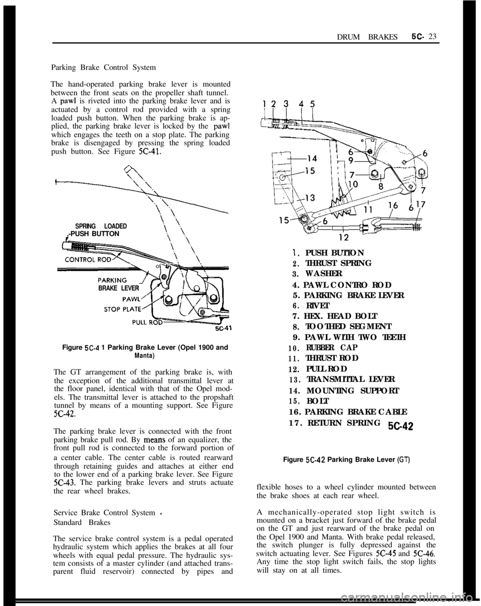
Parking Brake Control System
The hand-operated parking brake lever is mounted
between the front seats on the propeller shaft tunnel.
A paw1 is riveted into the parking brake lever and is
actuated by a control rod provided with a spring
loaded push button. When the parking brake is ap-
plied, the parking brake lever is locked by the
paw1which engages the teeth on a stop plate. The parking
brake is disengaged by pressing the spring loaded
push button. See Figure
5C-41.
SPRING LOADED,-PUSH BUTTON
BRAKE LEVER
s\., \\,Figure
5C-4 1 Parking Brake Lever (Opel 1900 and
Manta)The GT arrangement of the parking brake is, with
the exception of the additional transmittal lever at
the floor panel, identical with that of the Opel mod-
els. The transmittal lever is attached to the propshaft
tunnel by means of a mounting support. See Figure
5C-42.The parking brake lever is connected with the front
parking brake pull rod. By means of an equalizer, the
front pull rod is connected to the forward portion of
a center cable. The center cable is routed rearward
through retaining guides and attaches at either end
to the lower end of a parking brake lever. See Figure
5C-43. The parking brake levers and struts actuate
the rear wheel brakes.
Service Brake Control System
-Standard Brakes
The service brake control system is a pedal operated
hydraulic system which applies the brakes at all four
wheels with equal pedal pressure. The hydraulic sys-
tem consists of a master cylinder (and attached trans-
parent fluid reservoir) connected by pipes and
1.PUSH BUTTON
2.THRUST SPRING
3.WASHER
4. PAWL CONTRO ROD
5. PARKING BRAKE LEVER
6.RIVET
7. HEX. HEAD BOLT
8.TOOTHED SEGMENT
9. PAWL WITH TWO TEETH
10.RUBBER CAP
11.THRUST ROD
12.PULL ROD
13.TRANSMITTAL LEVER
14.MOUNTING SUPPORT
15.BOLT
16. PARKING BRAKE CABLE
17. RETURN SPRING
sea2Figure 5C-42 Parking Brake Lever
(GT)flexible hoses to a wheel cylinder mounted between
the brake shoes at each rear wheel.
A mechanically-operated stop light switch is
mounted on a bracket just forward of the brake pedal
on the GT and just rearward of the brake pedal on
the Opel 1900 and Manta. With brake pedal released,
the switch plunger is fully depressed against the
switch actuating lever. See Figures
5C-45 and 5C-46.Any time the stop light switch fails, the stop lights
will stay on at all times.
Page 474 of 625

AUTOMATIC TRANSMISSION 7C-113
12. Inspect the piston return springs. Evidence of
extreme heat or burning in the area of the clutch may
have caused the springs to take a heat set and would
justify replacement of the springs.
Figure 7C-16313. Inspect second clutch hub bushing for scoring or
wear.14. If necessary, remove second clutch hub bushing
using remover and installer J-23130-6 with driver
handle J-8092. See Figure 7C-164.
P-J-6092
SECOND CLUTCH
DRUM
iJ:23130-6Figure
7C-16415. Clean in solvent to remove any foreign matter.
Install new second clutch hub bushing using tool
J-23 130-6 and driver handle J-8092. Bushing must be
driven in until tool bottoms on bench. See Figure 7C-
164.16. To install second clutch piston into second clutch
drum, use installer tool J-23080 so as not to damage
lip seal. See Figure 7C-165. Use liberal amount of
transmission fluid for ease of installation and to pre-
vent seal damage.
SECOND CLUTCHDRUM
J-23,060Figure
7C-16517. Remove second clutch piston and seal installer
J-23080.18. Install 22 springs and retaining seat on second
clutch piston.
19. Using spring compressor tool J-2590-12 with
adapter J-21420-1 on retaining seat, compress sec-
ond clutch piston return springs. Care should be
taken so that retainer does not catch in snap ring
groove and damage retainer.
20. Install snap ring with snap ring pliers such as
J-
8059.21. Install bronze thrust washer so that the tang seats
in the slot of the second clutch hub. Secure with
petroleum jelly (unmedicated).
22. Inspect condition of composition and steel plates.
Do not diagnose a composition drive plate by co/or.
A. Dry composition plates with compressed air and
inspect the composition surface for:
1. Pitting and flaking
2. Wear
3. Glazing
Page 475 of 625

7C-1141973 OPEL SERVICE MANUAL
4. Cracking
5. Charring
6. Chips or metal particles imbedded in lining
If a composition drive plates exhibits any of the
above conditions, replacement is required.
B. Wipe steel plates dry and check for heat discolora-
tion. If the surface is smooth and an even color smear
is indicated, the plates should be reused. If severe
heat spot discoloration or surface scufftng is in-
dicated, the plates must be replaced.
23. Install second clutch plates into second clutch
drum with cushion plate (wave washer) first, then
steel plate, composition plate, steel plate, etc. Use
liberal amount of transmission fluid. See Figure 7C-
166.
-I
DRUM
7c-167Figure 7C-167
Disassembly, Inspection and Reassembly of Third
Clutch1. Compress third clutch sprag race and retainer
assembly retaining ring, and remove assembly from
third clutch drum. See Figure
7C-168. Third clutch
hub and input sun gear assembly will be removed at
the same time.
Figure 7C-16624. Install second clutch spacer plate into second
clutch drum. If necessary, expand spacer plate with
screw driver until ends of spacer are evenly butted
together seating tightly into drum. See Figure 7C-
159.
25. Install second clutch spacer retaining ring
26. Install ring gear into second clutch drum.
Figure 7C-168
27. Install ring gear retaining ring.
28. Air check second clutch assembly. See Figure7C- 167.2. Remove input sprag race and retainer assembly
from third clutch hub and input sun gear assembly.
See Figure
7C-169.
Page 477 of 625

7C.1161973 OPEL SERVICE MANUALDRUM
THIRD CLUTCH
PISTON
70174Figure 7C-174
damaged, replace piston. Install new lip seal on pis-
ton. See Figure
7C-175.
CHECKTHI
Figure 7C-175
12. Install new oil lip seal on input shaft inside of
third clutch drum. See Figure
7C-176.13. Inspect steel thrust washer on front face of third
clutch drum. Replace if scored or damaged. See Fig-
ure 7c-177.
14. Install third clutch piston into third clutch drum
using a
.020 music wire crimped into a piece of cop-
per tubing and a liberal amount of transmission fluidFigure 7C-176
Figure 7C-177
so that lip seal is not damaged upon installation. See
Figure
7C-178.15. Install the 12 third clutch piston return springs
onto piston.
16. Install retaining seat.
17. Using compressor tool J-23075 on retaining seat,
compress piston return springs. Care must be taken
so that retaining seat does not catch in snap ring
groove and damage retainer.
18. Install snap ring using snap ring pliers such as J-
8059.