jump start Ram 3500 2020 Owner's Manual
[x] Cancel search | Manufacturer: RAM, Model Year: 2020, Model line: 3500, Model: Ram 3500 2020Pages: 568
Page 10 of 568
8
BULB REPLACEMENT ....................................... 351 Replacement Bulbs ..................................351Replacing Exterior Bulbs ...........................353
FUSES .................................................................. 358
Power Distribution Center .........................358
JACKING AND TIRE CHANGING ...................... 365
Jack Location .............................................365Removal Of Jack And Tools .......................365
Removing The Spare Tire ..........................367
Preparations For Jacking...........................368
Jacking Instructions ...................................368
To Stow The Flat Or Spare ........................ 372Reinstalling The Jack And Tools ...............373
Hub Caps/Wheel Covers — If Equipped ...374
JUMP STARTING ................................................ 375
Preparations For Jump Start .....................375Jump Starting Procedure...........................376
GEAR SELECTOR OVERRIDE — 6–SPEED
TRANSMISSION ................................................ 377
MANUAL PARK RELEASE — 8 – SPEED
TRANSMISSION ................................................ 378
IF YOUR ENGINE OVERHEATS ......................... 379
FREEING A STUCK VEHICLE ............................ 380 TOWING A DISABLED VEHICLE .......................381
Two-Wheel Drive Models ........................... 382
Four-Wheel Drive Models .......................... 383Emergency Tow Hooks — If Equipped ...... 384
ENHANCED ACCIDENT RESPONSE
SYSTEM (EARS) ................................................. 384
EVENT DATA RECORDER (EDR) .......................384
SERVICING AND MAINTENANCE
SCHEDULED SERVICING — GAS ENGINE .......385
Maintenance Plan — Gasoline Engine...... 386
Heavy Duty Use Of The Vehicle................. 389
SCHEDULED SERVICING— DIESEL ENGINE .... 389
Oil Change Indicator System —
Cummins Diesel......................................... 390 Perform Service Indicator —
Cummins Diesel ........................................ 390 Maintenance Plan — Cummins Diesel
Engine ........................................................ 391
ENGINE COMPARTMENT .................................. 396
6.4L Engine ................................................ 396
6.7L Diesel Engine — Six-Speed 68RFE ... 397
6.7L Diesel Engine — Six-Speed AISIN
(AS69RC HD) .............................................. 398 Checking Oil Level — Gas Engine ............. 399
Checking Oil Level — Diesel Engine .......... 399
Adding Washer Fluid ................................. 399Maintenance-Free Battery ....................... 400Pressure Washing...................................... 400
DEALER SERVICE .............................................. 401
Engine Oil .................................................. 401
Engine Oil Filter ......................................... 403Engine Air Cleaner Filter ........................... 403
Air Conditioner Maintenance ................... 405
Accessory Drive Belt Inspection ............... 408Draining Fuel/Water Separator Filter —
Diesel Engine ............................................ 409 Engine Mounted Fuel Filter
Replacement — Diesel Engine .................. 410 Underbody Mounted Fuel Filter
Replacement — Diesel Engine .................. 412 Priming If The Engine Has Run Out Of
Fuel — Diesel Engine ................................. 412 Intervention Regeneration Strategy —
Message Process Flow ............................. 413 Diesel Exhaust Fluid .................................. 414
Body Lubrication ........................................ 414
20_DJD2_OM_EN_USC_t.book Page 8
Page 218 of 568

216STARTING AND OPERATING
If the driver shifts into PARK while moving, the
vehicle may AutoPark.
AutoPark will engage ONLY when vehicle speed
is 1.2 mph (1.9 km/h) or less.
The message “ Vehicle Speed is Too High to
Shift to P ” will be displayed in the instrument
cluster if vehicle speed is above 1.2 mph
(1.9 km/h).
4WD LOW — If Equipped
AutoPark will be disabled when operating the
vehicle in 4WD LOW.
The message “ AutoPark Disabled ” will be
displayed in the instrument cluster. Additional customer warnings will be given
when all of these conditions are met:
Vehicle is not in PARK
Driver’s door is ajar
Vehicle is in 4WD LOW range
The message “ AutoPark Not Engaged ” will be
displayed in the instrument cluster. A warning
chime will continue until you shift the vehicle
into PARK or the driver’s door is closed.
ALWAYS DO A VISUAL CHECK
that your vehicle
is in PARK by looking for the “P” in the
Instrument Cluster Display and near the shifter.
As an added precaution, always apply the
parking brake when exiting the vehicle.
If Engine Fails To Start
If the engine fails to start after you have
followed the “Normal Starting” procedure, it
may be flooded. Push the accelerator pedal all
the way to the floor and hold it there while the
engine is cranking. This should clear any excess
fuel in case the engine is flooded. The starter motor will engage automatically, run
for 10 seconds, and then disengage. Once this
occurs, release the accelerator pedal and the
brake pedal, wait 10 to 15 seconds, then repeat
the “Normal Starting” procedure.
WARNING!
If vehicle speed is above 1.2 mph (1.9 km/h),
the transmission will default to NEUTRAL until
the vehicle speed drops below 1.2 mph
(1.9 km/h). A vehicle left in the NEUTRAL
position can roll. As an added precaution,
always apply the parking brake when exiting
the vehicle.
WARNING!
Never pour fuel or other flammable liquid
into the throttle body air inlet opening in an
attempt to start the vehicle. This could result
in flash fire causing serious personal injury.
Do not attempt to push or tow your vehicle to
get it started. Vehicles equipped with an
automatic transmission cannot be started
this way. Unburned fuel could enter the cata
-
lytic converter and once the engine has
started, ignite and damage the converter
and vehicle.
If the vehicle has a discharged battery,
booster cables may be used to obtain a
start from a booster battery or the battery in
another vehicle. This type of start can be
dangerous if done improperly. Refer to
“Jump Starting Procedure” in “In Case Of
Emergency” for further information.
20_DJD2_OM_EN_USC_t.book Page 216
Page 377 of 568
IN CASE OF EMERGENCY375
(Continued)
Replace the wheel covers using a rubber mallet
to ease the installation. Align the wheel cover
vent holes to the wheel vent holes. Tap on the
wheel cover as needed to firmly seat it evenly
around the wheel.
JUMP STARTING
If your vehicle has a discharged battery, it can
be jump started using a set of jumper cables
and a battery in another vehicle, or by using a
portable battery booster pack. Jump starting
can be dangerous if done improperly, so please
follow the procedures in this section carefully. NOTE:
When using a portable battery booster pack,
follow the manufacturer's operating instruc
-
tions and precautions.
PREPARATIONS FOR JUMP START
The battery in your vehicle is located in the front
of the engine compartment, behind the driver
side headlight assembly.
NOTE:
If you have a diesel engine, you may have two
batteries, however jump start off the driver
side battery.
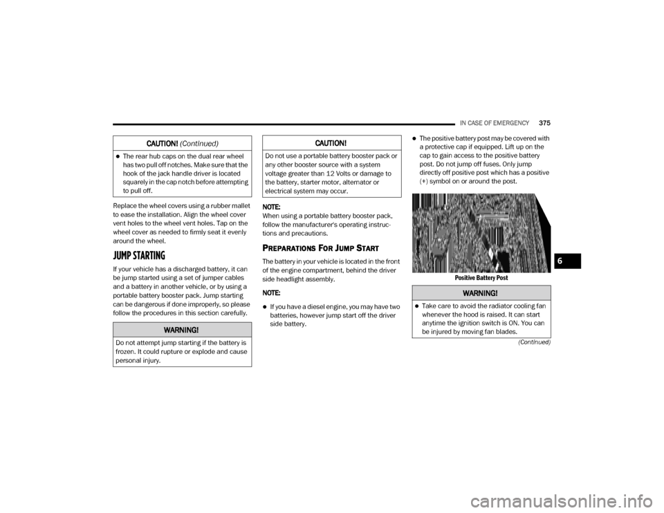
The positive battery post may be covered with
a protective cap if equipped. Lift up on the
cap to gain access to the positive battery
post. Do not jump off fuses. Only jump
directly off positive post which has a positive
(+) symbol on or around the post.
Positive Battery Post
The rear hub caps on the dual rear wheel
has two pull off notches. Make sure that the
hook of the jack handle driver is located
squarely in the cap notch before attempting
to pull off.
WARNING!
Do not attempt jump starting if the battery is
frozen. It could rupture or explode and cause
personal injury.
CAUTION! (Continued)CAUTION!
Do not use a portable battery booster pack or
any other booster source with a system
voltage greater than 12 Volts or damage to
the battery, starter motor, alternator or
electrical system may occur.
WARNING!
Take care to avoid the radiator cooling fan
whenever the hood is raised. It can start
anytime the ignition switch is ON. You can
be injured by moving fan blades.
6
20_DJD2_OM_EN_USC_t.book Page 375
Page 378 of 568
376IN CASE OF EMERGENCY
1. Apply the parking brake, shift the
automatic transmission into PARK and
turn the ignition OFF.
2. Turn off the heater, radio, and all unnecessary electrical accessories.
3. If using another vehicle to jump start the battery, park the vehicle within the jumper
cables’ reach, apply the parking brake and
make sure the ignition is OFF.
JUMP STARTING PROCEDURE
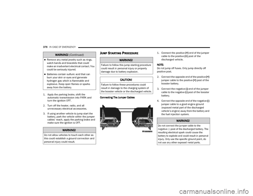
Connecting The Jumper Cables
1. Connect the positive
(+) end of the jumper
cable to the positive (+)
post of the
discharged vehicle.
NOTE:
Do not jump off fuses. Only jump directly off
positive post.
2. Connect the opposite end of the positive (+)
jumper cable to the positive (+) post of the
booster battery.
3. Connect the negative (-) end of the jumper
cable to the negative (-) post of the booster
battery.
4. Connect the opposite end of the negative (-)
jumper cable to a good engine ground
(exposed metal part of the discharged
vehicle’s engine) away from the battery and
the fuel injection system.
Remove any metal jewelry such as rings,
watch bands and bracelets that could
make an inadvertent electrical contact. You
could be seriously injured.
Batteries contain sulfuric acid that can
burn your skin or eyes and generate
hydrogen gas which is flammable and
explosive. Keep open flames or sparks
away from the battery.
WARNING!
Do not allow vehicles to touch each other as
this could establish a ground connection and
personal injury could result.
WARNING! (Continued)
WARNING!
Failure to follow this jump starting procedure
could result in personal injury or property
damage due to battery explosion.
CAUTION!
Failure to follow these procedures could
result in damage to the charging system of
the booster vehicle or the discharged vehicle.
WARNING!
Do not connect the jumper cable to the
negative (-) post of the discharged battery. The
resulting electrical spark could cause the
battery to explode and could result in personal
injury. Only use the specific ground point, do
not use any other exposed metal parts.
20_DJD2_OM_EN_USC_t.book Page 376
Page 379 of 568
IN CASE OF EMERGENCY377
5. Start the engine in the vehicle that has the
booster battery, let the engine idle a few
minutes, and then start the engine in the
vehicle with the discharged battery.
6. Once the engine is started, remove the jumper cables in the reverse sequence.
Disconnecting The Jumper Cables
1. Disconnect the negative
(-)
end of the
jumper cable from the engine ground of
the vehicle with the discharged battery.
2. Disconnect the opposite end of the negative (-) jumper cable from the negative (-) post of
the booster battery.
3. Disconnect the positive (+) end of the
jumper cable from the positive (+) post of
the booster battery.
4. Disconnect the opposite end of the positive (+) jumper cable from the positive (+) post
of the vehicle with the discharged battery.
If frequent jump starting is required to start your
vehicle you should have the battery and charging
system inspected at an authorized dealer.
GEAR SELECTOR OVERRIDE — 6–SPEED
TRANSMISSION
If a malfunction occurs and the gear selector
cannot be moved out of the PARK position, you
can use the following procedure to temporarily
move the gear selector:
1. Turn the engine OFF.
2. Firmly apply the parking brake.
3. Tilt the steering wheel to the full up position.
4. Press and maintain firm pressure on the
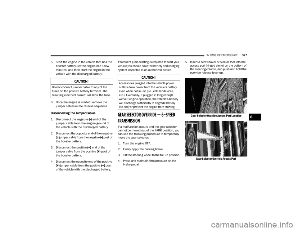
brake pedal. 5. Insert a screwdriver or similar tool into the
access port (ringed circle) on the bottom of
the steering column, and push and hold the
override release lever up.
Gear Selector Override Access Port Location Gear Selector Override Access Port
CAUTION!
Do not connect jumper cable to any of the
fuses on the positive battery terminal. The
resulting electrical current will blow the fuse.
CAUTION!
Accessories plugged into the vehicle power
outlets draw power from the vehicle’s battery,
even when not in use (i.e., cellular devices,
etc.). Eventually, if plugged in long enough
without engine operation, the vehicle’s battery
will discharge sufficiently to degrade battery
life and/or prevent the engine from starting.
6
20_DJD2_OM_EN_USC_t.book Page 377
Page 402 of 568

400SERVICING AND MAINTENANCE
After the engine has warmed up, operate the
defroster for a few minutes to reduce the
possibility of smearing or freezing the fluid on
the cold windshield. Windshield washer solution
used with water as directed on the container,
aids cleaning action, reduces the freezing point
to avoid line clogging, and is not harmful to
paint or trim.
MAINTENANCE-FREE BATTERY
Your vehicle is equipped with a
maintenance-free battery. You will never have
to add water, nor is periodic maintenance
required.
PRESSURE WASHING
WARNING!
Commercially available windshield washer
solvents are flammable. They could ignite and
burn you. Care must be exercised when filling
or working around the washer solution.
WARNING!
Battery fluid is a corrosive acid solution and
can burn or even blind you. Do not allow
battery fluid to contact your eyes, skin, or
clothing. Do not lean over a battery when
attaching clamps. If acid splashes in eyes
or on skin, flush the area immediately with
large amounts of water. Refer to “Jump
Starting Procedure” in “In Case Of Emer -
gency” for further information.
Battery gas is flammable and explosive.
Keep flame or sparks away from the
battery. Do not use a booster battery or any
other booster source with an output greater
than 12 Volts. Do not allow cable clamps to
touch each other.
Battery posts, terminals, and related acces -
sories contain lead and lead compounds.
Wash hands after handling.
CAUTION!
It is essential when replacing the cables on
the battery that the positive cable is
attached to the positive post and the nega -
tive cable is attached to the negative post.
Battery posts are marked positive (+) and
negative (-) and are identified on the battery
case. Cable clamps should be tight on the
terminal posts and free of corrosion.
If a “fast charger” is used while the battery
is in the vehicle, disconnect both vehicle
battery cables before connecting the
charger to the battery. Do not use a “fast
charger” to provide starting voltage.
CAUTION!
Cleaning the engine compartment with a high
pressure washer is not recommended.
Precautions have been taken to safeguard all
parts and connections however, the
pressures generated by these machines is
such that complete protection against water
ingress cannot be guaranteed.
20_DJD2_OM_EN_USC_t.book Page 400
Page 411 of 568

SERVICING AND MAINTENANCE409
When inspecting accessory drive belts, small
cracks that run across ribbed surface of belt
from rib to rib, are considered normal. These
are not a reason to replace belt. However,
cracks running along a rib (not across) are not
normal. Any belt with cracks running along a rib
must be replaced. Also have the belt replaced if
it has excessive wear, frayed cords or severe
glazing.
Accessory Belt (Serpentine Belt)
Conditions that would require replacement:
Rib chunking (one or more ribs has sepa -
rated from belt body)
Rib or belt wear
Longitudinal belt cracking (cracks between
two ribs)
Belt slips
“Groove jumping" (belt does not maintain
correct position on pulley)
Belt broken (note: identify and correct
problem before new belt is installed)
Noise (objectionable squeal, squeak, or
rumble is heard or felt while drive belt is in
operation)
Some conditions can be caused by a faulty
component such as a belt pulley. Belt pulleys
should be carefully inspected for damage and
proper alignment.
Belt replacement on some models requires the
use of special tools, we recommend having your
vehicle serviced at an authorized dealer.
DRAINING FUEL/WATER SEPARATOR
F
ILTER — DIESEL ENGINE
There are two fuel filter assemblies. One is
located on the driver's side of the engine. The
best access to this water drain valve is from
under the hood. The second one is on the under
body, located in front of the rear axle above the
drive shaft on pick-up models. The Chassis Cab models second filter location is on the frame
behind the front axle. The best access to this
water drain valve is from under the vehicle.
If water is detected in the water separator while
the engine is running, or while the ignition
switch is in the ON position, the “Water In Fuel
Indicator Light” will illuminate and an audible
chime will be heard five times. At this point you
should stop the engine and drain the water from
both of the filters.
CAUTION!
Do not drain the fuel/water separator filter
when the engine is running.
Diesel fuel will damage blacktop paving
surfaces. Drain the filter into an appro-
priate container.
CAUTION!
If the “Water In Fuel Indicator Light” remains
on, DO NOT START the engine before you
drain water from the fuel filters to avoid
engine damage.
7
20_DJD2_OM_EN_USC_t.book Page 409
Page 532 of 568
530MULTIMEDIA
Track Selection (Browse)
Rotate the Browse button on the touchscreen to
scroll through and select a desired track on the
iPod®, MP3 player, phone, or USB. Press the
Exit button on the touchscreen if you wish to
cancel the Browse function.
Repeat
Press the Repeat button on the touchscreen to
repeat the song selection. To cancel Repeat,
press the Repeat button on the touchscreen a
second time.
Shuffle
Press the Shuffle button on the touchscreen to
play the selections on the USB/iPod® or
Bluetooth® device in random order to provide
an interesting change of pace. Press the Shuffle
button on the touchscreen a second time to
turn this feature off.
Track Info
Press the Info button on the touchscreen to
display the current track information. Press the
X button on the touchscreen to cancel this
feature.
Audio
Refer to “Audio Settings” for the adjustable
audio settings.
USB/iPod® Mode
USB/iPod® Mode is entered by either inserting
a USB Jump Drive or iPod® cable into the USB
port, or by pushing the MEDIA button located on
the faceplate. Once in Media Mode, press the
Source button on the touchscreen, and select
the USB/iPod® button.
Inserting USB/iPod® Device
Gently insert the USB/iPod® device into the
USB Port. If you insert a USB/iPod® device with
the ignition ON, the unit will switch to USB/
iPod® mode and begin to play when you insert
the device. The display will show the track
number and index time in minutes and
seconds. Play will begin at the start of track 1.
Browse
Press the Browse button on the touchscreen to
select Artist, Albums, Genres, Songs, Playlists or
Folders from the USB/iPod® device. Once the
desired selection is made you can chose from the available media by pressing the button on
the touchscreen. Press the Exit button on the
touchscreen if you wish to cancel the Browse
function.Bluetooth® Mode
Bluetooth® Streaming Audio (BTSA) or
Bluetooth® Mode is entered by pairing a
Bluetooth® device containing music to the
Uconnect system.
Before proceeding, the Bluetooth® device must
be paired with the Uconnect Phone to
communicate with the Uconnect system.
Refer to Phone Mode section for pairing
procedure.
Once the Bluetooth® device is paired to the
Uconnect system, push the MEDIA button
located on the faceplate. Once in Media Mode,
press the Source button on the touchscreen
and select the Bluetooth® button.
NOTE:
For mobile phone compatibility and pairing
instructions, please visit UconnectPhone.com.
20_DJD2_OM_EN_USC_t.book Page 530
Page 556 of 568
554 Diesel Fuel System, Re-Priming
..................... 412Differential, Limited Slip................................ 270Disabled Vehicle Towing................................ 381Disposal Antifreeze (Engine Coolant)....................... 420Do Not Disturb............................................... 545Door Ajar........................................................ 133Door Ajar Light............................................... 133Door LocksAutomatic.................................................... 30Doors............................................................... 26Draining Fuel/Water Separator Filter............ 409Driver’s Seat Back Tilt..................................... 33DrivingOff-Pavement............................................ 261Off-Road.................................................... 261Through Flowing, Rising, Or Shallow Standing Water..................................... 343Dual Rear Wheels................................ 445, 452
E
Electric Brake Control System....................... 145Anti-Lock Brake System............................. 144Electronic Roll Mitigation................. 149, 153Electrical Power Outlets................................... 86Electronic Range Select (ERS)............. 238, 243Electronic Stability Control (ESC)...................146Electronic Throttle Control Warning Light...... 132Electronically Shifted Transfer Case.... 246, 250Emergency Braking........................................ 231
Emergency, In Case OfFreeing Vehicle When Stuck..................... 380Hazard Warning Flasher........................... 346Jump Starting........................................... 375Emission Control System Maintenance........ 143Engine......................................... 396, 397, 398Air Cleaner................................................ 403Block Heater.................................... 220, 229Break-In Recommendations..................... 230Compartment.................................. 397, 398Compartment Identification...................... 396Coolant (Antifreeze)......................... 461, 464Exhaust Gas Caution....................... 209, 456Fails To Start............................................ 216Flooded, Starting...................................... 216Fuel Requirements.......................... 454, 459Identifcation.................................... 397, 398Idling........................................................ 226Jump Starting........................................... 375Oil..................................401, 459, 461, 464Oil Filler Cap.................................... 396, 402Oil Filter.................................................... 403Oil Reset................................................... 115Oil Selection.................................... 401, 459Oil Synthetic............................................. 403Overheating.............................................. 379Runaway................................................... 319Starting..................................................... 214Engine Oil Viscosity....................................... 402
Enhanced Accident Response Feature...189, 384
Entry System, Illuminated................................54Ethanol.......................................................... 454Exhaust Brake............................................... 232Exhaust Gas Cautions.......................... 209, 456Exhaust System..........................209, 416, 425Exterior Lighting...............................................48Exterior Lights........................................ 48, 212
F
FiltersAir Cleaner
................................................ 403Air Conditioning................................. 69, 406Engine Fuel............................................... 409Engine Oil............................... 403, 461, 464Engine Oil Disposal................................... 403FlashersTurn Signals.............................. 51, 141, 212Flash-To-Pass...................................................50Flat Tire Stowage.......................................... 372Fluid Capacities................................... 459, 460Fluid Leaks.................................................... 212Fluid Level ChecksBrake........................................................ 421Fluid, Brake................................................... 463Fluids And Lubricants........................... 461, 464Fog Lights.............................................. 51, 355Fold Flat Load Floor.........................................84Fold-Flat Seats.................................................33Forward Collision Warning............................ 160Four Wheel Drive........................................... 246
20_DJD2_OM_EN_USC_t.book Page 554
Page 558 of 568
556 J
Jack Location
................................................. 365Jump Starting................................................ 375
K
Key Fob Panic Alarm
................................................. 15Programming Additional Key Fobs....... 16, 24Key Fob Battery Service (Remote
Keyless Entry).................................................. 15
Key Fob Programming (Remote Keyless Entry).. 16
Keyless Enter-N-Go........................28, 214, 218Lock The Vehicle’s Doors....... 476, 494, 514Passive Entry............................................... 28Passive Entry Programming............. 494, 514Keys................................................................. 14Replacement............................................... 24
L
Lane Change And Turn Signals........................ 51Lane Change Assist......................................... 52LaneSense.................................................... 306Latches.......................................................... 212Hood........................................................... 74Lead Free Gasoline........................................ 454Leaks, Fluid................................................... 212Life Of Tires................................................... 439Light Bulbs........................................... 212, 351
Lights............................................................ 212Air Bag.................................... 130, 182, 210Automatic High Beam.................................. 49Brake Assist Warning............................... 148Brake Warning.......................................... 131Bulb Replacement.................................... 351Cab Top Clearance................................... 357Cargo........................................................... 52Center Mounted Stop............................... 356Courtesy/Reading....................................... 53Cruise....................................................... 141Daytime Running......................................... 49
Electronic Stability Program(ESP) Indicator... 132
Exterior...............................................48, 212Fog........................................................... 355Four Wheel Drive Indicator....................... 255Hazard Warning Flasher........................... 346Headlights............................................ 48, 50High Beam................................................... 49Hill Descent Control Indicator................... 149Illuminated Entry......................................... 54Interior......................................................... 53Lights On Reminder..................................... 51Low Fuel................................................... 135Malfunction Indicator (Check Engine)....... 133Park.......................................................... 140Passing........................................................ 50Seat Belt Reminder.................................. 130Security Alarm.......................................... 132Service..................................................... 351
Side Marker.............................................. 357Traction Control........................................ 148Transfer Case........................................... 255Turn Signals............51, 141, 212, 353, 355Warning Instrument Cluster Descriptions................................ 132, 141Limited-Slip Differential....................... 270, 424Load Shed Battery Saver Mode..................... 129Load Shed Battery Saver On......................... 129Load Shed Electrical Load Reduction........... 129Load Shed Intelligent Battery Sensor............ 129Loading Vehicle............................................. 324Tires.......................................................... 433LocksAutomatic Door............................................30Child Protection...........................................30Power Door..................................................27Low Tire Pressure System............................. 163Lubrication, Body.......................................... 414Lug Nuts/Bolts.............................................. 452
M
Maintenance....................................................73Maintenance Free Battery............................ 400Maintenance Plan......................................... 391Maintenance Schedule............... 385, 389, 391Malfunction Indicator Light
(Check Engine)..................................... 133, 143
20_DJD2_OM_EN_USC_t.book Page 556