lock Ram 4500 Chassis Cab 2018 Owner's Manual
[x] Cancel search | Manufacturer: RAM, Model Year: 2018, Model line: 4500 Chassis Cab, Model: Ram 4500 Chassis Cab 2018Pages: 298, PDF Size: 5.88 MB
Page 24 of 298
Programming The Memory Feature
To create a new memory profile, perform the
following:
1. Cycle the vehicle’s ignition to the ON/RUN position (do not start the engine).
2. Adjust all memory profile settings to de- sired preferences (i.e., driver’s seat, out-
side mirrors and radio station presets).
3. Push and release the set (S) button on the memory switch.
4. Within five seconds, push and release either of the memory buttons (1) or (2).
The instrument cluster display will show
which memory position has been set.
NOTE:
• Memory profiles can be set without the vehicle in PARK, but the vehicle must be in
PARK to recall a memory profile.
• To set a memory profile to your key fob, refer to “Linking And Unlinking The Re-
mote Keyless Entry Key Fob To Memory” in
this section.
Linking And Unlinking The Remote Keyless
Entry Key Fob To Memory
Your key fobs can be programmed to recall
one of two pre-programmed memory profiles
by pushing the unlock button on the key fob.
NOTE:
Before programming your key fobs to memory
the feature has to be selected.
• If your vehicle is equipped with a touch-screen, you must select the “Memory To
Fob” feature through the Uconnect system.
Refer to “Uconnect Settings” in “Multimedia”
in the Owner’s Manual at
www.mopar.com/
en-us/care/owners-manual.html (U.S.
Residents) or www.owners.mopar.ca
(Canadian Residents) for further information.
• If your vehicle is not equipped with a touch- screen, you must select the “Key Fob
Linked To Memory” feature through the
instrument cluster display. Refer to “In-
strument Cluster Display” in “Getting To
Know Your Instrument Panel” in the Own-
er’s Manual at www.mopar.com/en-us/
care/owners-manual.html (U.S. Residents)
or www.owners.mopar.ca (Canadian
Residents) for further information. To program your key fobs, perform the follow-
ing:
1. Cycle the vehicle’s ignition to the OFF
position.
2. Select desired memory profile (1) or (2).
NOTE:
If a memory profile has not already been
set, refer to "Programming The Memory
Feature" for instructions on how to set a
memory profile.
3. Once the profile has been recalled, push and release the set (S) button on the
memory switch, then push and release
button (1) or (2) accordingly. “Memory
Profile Set” (1 or 2) will display in the
instrument cluster display.
4. Push and release the lock button on the key fob within 10 seconds.
NOTE:
Your key fobs can be unlinked to your memory
settings by pushing the set (S) button, and
within 10 seconds, followed by pushing the
unlock button on the key fob.GETTING TO KNOW YOUR VEHICLE
22
Page 25 of 298
Memory Position Recall
NOTE:
• For vehicles equipped with an automatictransmission, the vehicle speed must be
lower than 5 mph to recall memory posi-
tions. If a recall is attempted when the
vehicle speed is greater than 5 mph, a
message will be displayed in the instru-
ment cluster display.
• For vehicles equipped with a manual trans- mission, the vehicle speed must be at
0 mph (0 km/h) to recall memory positions.
If a recall is attempted with the vehicle
speed above 0 mph (0 km/h), a message
will appear in the instrument cluster
display.
Driver One Memory Position Recall
• To recall the memory settings for driver one using the memory switch, push memory
button (1) on the memory switch.
• To recall the memory settings for driver one using the key fob, push the unlock button
on the key fob linked to memory position 1. Driver Two Memory Position Recall
• To recall the memory setting for driver two
using the memory switch, push memory
button (2) on the memory switch.
• To recall the memory settings for driver two using the key fob, push the unlock button
on the key fob linked to memory position 2.
A recall can be cancelled by pushing any of
the memory buttons during a recall (S, 1, or
2). When a recall is cancelled, the driver's
seat and the power pedals (if equipped) stop
moving. A delay of one second will occur
before another recall can be selected.
Easy Entry/Exit Seat
This feature provides automatic driver’s seat
positioning to enhance driver mobility when
entering and exiting the vehicle.
The distance the driver’s seat moves depends
on where you have the driver’s seat positioned
when you remove the key fob from the igni-
tion (or change the ignition to OFF, for ve-
hicles equipped with Keyless Enter-N-Go). • When you remove the key fob from the
ignition (or change the ignition to OFF, for
vehicles equipped with Keyless Enter-N-
Go), the driver’s seat will move about
2.4 inches (60 mm) rearward if the driver’s
seat position is greater than or equal to
2.7 inches (67.7 mm) forward of the rear
stop. The seat will return to its previously
set position when you place the ignition
into the ACC or RUN position.
• When you remove the key fob from the ignition (or change the ignition to OFF, for
vehicles equipped with Keyless Enter-N-
Go), the driver’s seat will move to a position
0.3 inches (7.7 mm) forward of the rear
stop if the driver’s seat position is between
0.9 inches and 2.7 inches (22.7 mm and
67.7 mm) forward of the rear stop. The seat
will return to its previously set position
when you place the ignition to the ACC or
RUN position.
• The Easy Entry/Easy Exit feature is disabled when the driver’s seat position is less than
0.9 inches (22.7 mm) forward of the rear
stop. At this position, there is no benefit to
the driver by moving the seat for Easy Exit
or Easy Entry.
23
Page 30 of 298
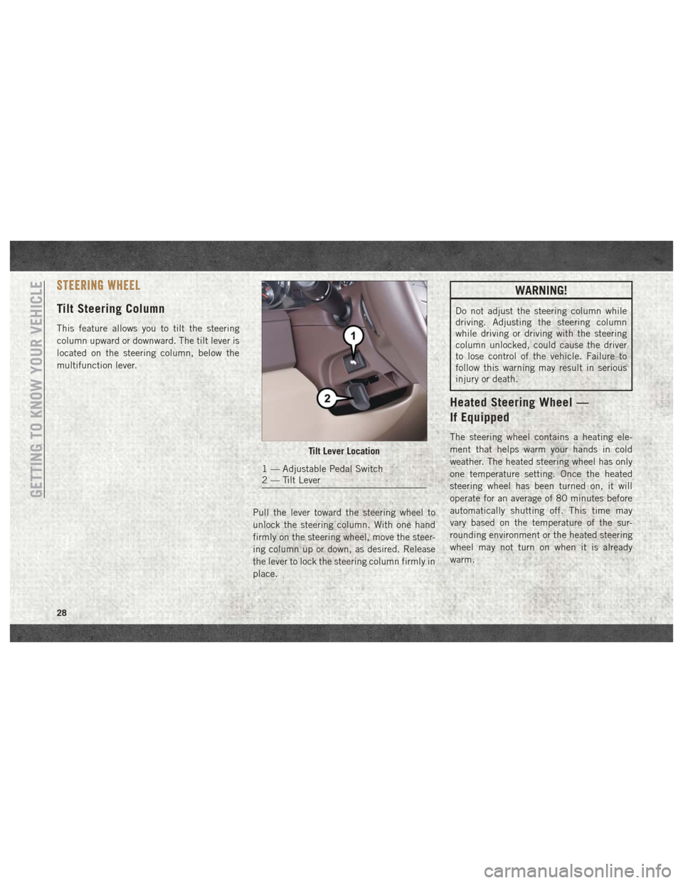
STEERING WHEEL
Tilt Steering Column
This feature allows you to tilt the steering
column upward or downward. The tilt lever is
located on the steering column, below the
multifunction lever.Pull the lever toward the steering wheel to
unlock the steering column. With one hand
firmly on the steering wheel, move the steer-
ing column up or down, as desired. Release
the lever to lock the steering column firmly in
place.
WARNING!
Do not adjust the steering column while
driving. Adjusting the steering column
while driving or driving with the steering
column unlocked, could cause the driver
to lose control of the vehicle. Failure to
follow this warning may result in serious
injury or death.
Heated Steering Wheel —
If Equipped
The steering wheel contains a heating ele-
ment that helps warm your hands in cold
weather. The heated steering wheel has only
one temperature setting. Once the heated
steering wheel has been turned on, it will
operate for an average of 80 minutes before
automatically shutting off. This time may
vary based on the temperature of the sur-
rounding environment or the heated steering
wheel may not turn on when it is already
warm.
Tilt Lever Location
1 — Adjustable Pedal Switch
2 — Tilt Lever
GETTING TO KNOW YOUR VEHICLE
28
Page 31 of 298
The heated steering wheel control button is
located on the center instrument panel below
the climate controls. There are also buttons
located within the climate or controls screen
of the touchscreen.
• Press the heated steering wheel button
once to turn the heating element on.
• Press the heated steering wheel button
a second time to turn the heating element
off.
NOTE:
The engine must be running for the heated
steering wheel to operate.
Vehicles Equipped With Remote Start
On models that are equipped with remote
start, the heated steering wheel can be pro-
grammed to come on during a remote start.
This feature can be programmed through the
Uconnect system. Refer to “Uconnect Set-
tings” in “Multimedia” in the Owner’s
Manual at www.mopar.com/en-us/care/
owners-manual.html (U.S. Residents) or
www.owners.mopar.ca (Canadian Residents)
for further information.
WARNING!
• Persons who are unable to feel pain to the skin because of advanced age,
chronic illness, diabetes, spinal cord in-
jury, medication, alcohol use, exhaus-
tion, or other physical conditions must
exercise care when using the steering
wheel heater. It may cause burns even at
low temperatures, especially if used for
long periods.
• Do not place anything on the steering
wheel that insulates against heat, such
as a blanket or steering wheel covers of
any type and material. This may cause
the steering wheel heater to overheat.
DRIVER ADJUSTABLE PEDALS —
IF EQUIPPED
The adjustable pedals system is designed to
allow a greater range of driver comfort for
steering wheel tilt and seat position. This
feature allows the brake, accelerator, and clutch pedals (if equipped) to move toward or
away from the driver to provide improved
position with the steering wheel.
The adjustable pedal switch is located to the
left side of the steering column.
• The pedals can be adjusted with the igni-
tion OFF.
• The pedals cannotbe adjusted when the
vehicle is in REVERSE or when the Speed
Control System is on. The following mes-
sages will appear on vehicles equipped with
an instrument cluster display if the pedals
are attempted to be adjusted when the
system is locked out: “Adjustable Pedal
Disabled — Cruise Control Engaged” or
“Adjustable Pedal Disabled — Vehicle In
Reverse”.
NOTE:
• Always adjust the pedals to a position that allows full pedal travel.
• Further small adjustments may be neces- sary to find the best possible seat/pedal
position.
29
Page 32 of 298
• For vehicles equipped with Driver MemorySeat, you can use your remote keyless entry
key fob or the memory switch on the driver’s
door trim panel to return the adjustable
pedals to pre-programmed positions. Refer
to “Driver Memory Seat” in “Getting To
Know Your Vehicle” for further information.
WARNING!
Do not adjust the pedals while the vehicle
is moving. You could lose control and have
an accident. Always adjust the pedals
while the vehicle is parked.
CAUTION!
Do not place any article under the adjust-
able pedals or impede its ability to move,
as it may cause damage to the pedal con-
trols. Pedal travel may become limited if
movement is stopped by an obstruction in
the adjustable pedal's path.
MIRRORS
Power Folding Outside Mirrors For
Standard And Trailer Tow —
If Equipped
If equipped with power folding mirrors, they
can be electrically folded rearward and un-
folded into the drive position.
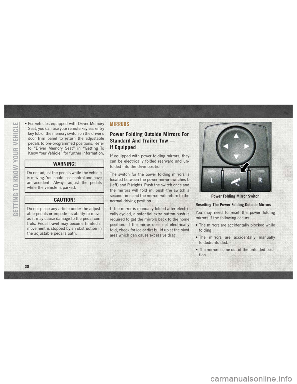
The switch for the power folding mirrors is
located between the power mirror switches L
(left) and R (right). Push the switch once and
the mirrors will fold in, push the switch a
second time and the mirrors will return to the
normal driving position.
If the mirror is manually folded after electri-
cally cycled, a potential extra button push is
required to get the mirrors back to the home
position. If the mirror does not electrically
fold, check for ice or dirt build up at the pivot
area which can cause excessive drag. Resetting The Power Folding Outside Mirrors
You may need to reset the power folding
mirrors if the following occurs:
• The mirrors are accidentally blocked while
folding.
• The mirrors are accidentally manually folded/unfolded.
• The mirrors come out of the unfolded posi- tion.
Power Folding Mirror Switch
GETTING TO KNOW YOUR VEHICLE
30
Page 34 of 298
breakage than glass lights. Plastic is not as
scratch resistant as glass and therefore dif-
ferent lens cleaning procedures must be fol-
lowed.
To minimize the possibility of scratching the
lenses and reducing light output, avoid wip-
ing with a dry cloth. To remove road dirt, wash
with a mild soap solution followed by rinsing.
NOTE:
If your vehicle is equipped with illuminated
approach lights under the outside mirrors,
they can be turned off through the instrument
cluster or the Uconnect radio. For further
information, refer to the Owner’s Manual at
www.mopar.com/en-us/care/owners-manual.html
(U.S. Residents) or www.owners.mopar.ca
(Canadian Residents) for further information.
CAUTION!
Do not use abrasive cleaning components,
solvents, steel wool or other abrasive ma-
terials to clean the lenses.
Headlights
To turn on the headlights, rotate the head-
light switch clockwise to the headlight posi-
tion. When the headlight switch is on, the
parking lights, taillights, license plate light
and instrument panel lights are also turned
on. To turn off the headlights, rotate the
headlight switch back to the O (off) position.
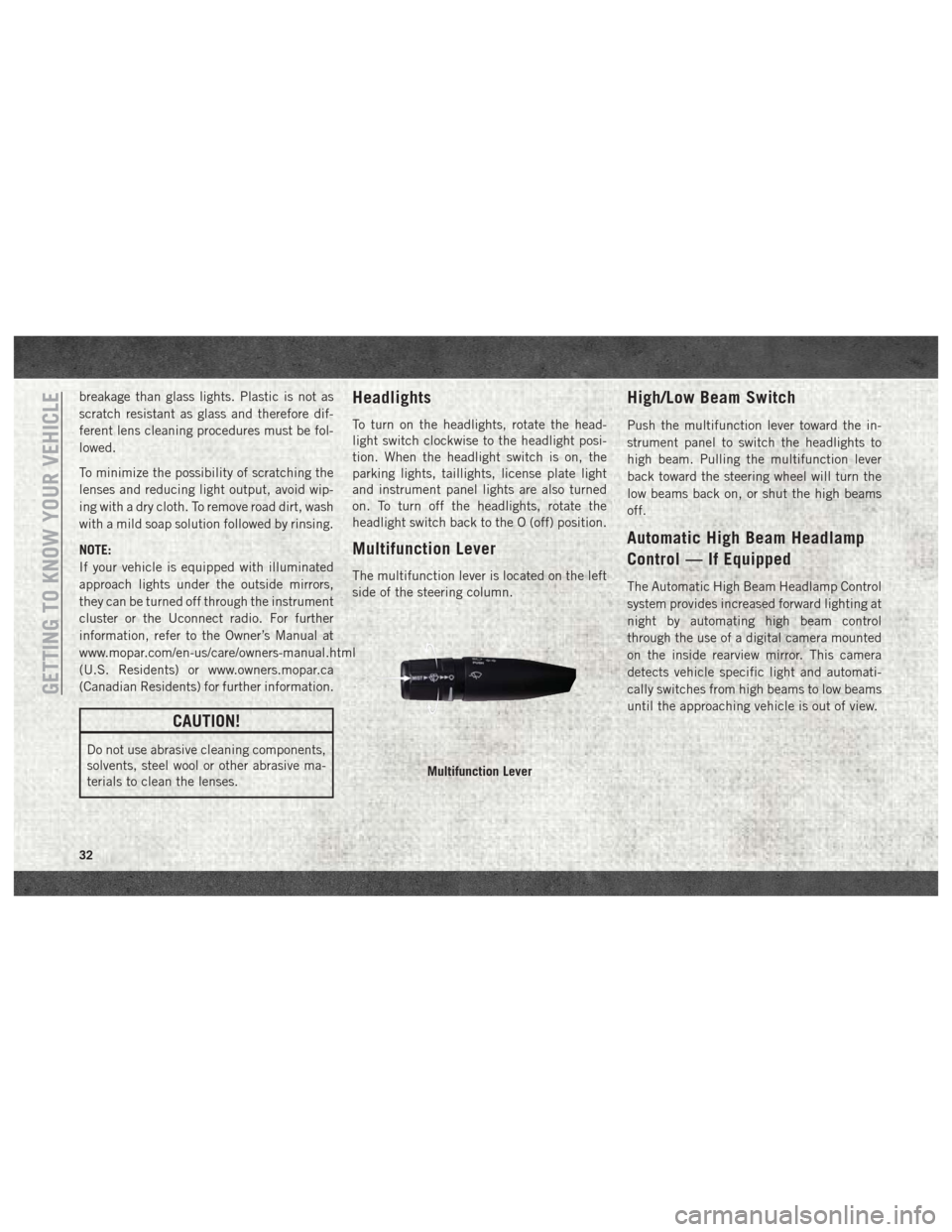
Multifunction Lever
The multifunction lever is located on the left
side of the steering column.
High/Low Beam Switch
Push the multifunction lever toward the in-
strument panel to switch the headlights to
high beam. Pulling the multifunction lever
back toward the steering wheel will turn the
low beams back on, or shut the high beams
off.
Automatic High Beam Headlamp
Control — If Equipped
The Automatic High Beam Headlamp Control
system provides increased forward lighting at
night by automating high beam control
through the use of a digital camera mounted
on the inside rearview mirror. This camera
detects vehicle specific light and automati-
cally switches from high beams to low beams
until the approaching vehicle is out of view.
Multifunction Lever
GETTING TO KNOW YOUR VEHICLE
32
Page 35 of 298
NOTE:
• The Automatic High Beam Headlamp Con-trol can be turned on or off by selecting
“ON” under “Auto High Beam” within your
Uconnect settings, as well as turning the
headlight switch to the AUTO position. Re-
fer to “Uconnect Settings” in “Multimedia”
in the Owner’s Manual at
www.mopar.com/en-us/care/owners-manual.html
(U.S. Residents) or www.owners.mopar.ca
(Canadian Residents) for further informa-
tion.
• Broken, muddy, or obstructed headlights and taillights of vehicles in the field of view
will cause headlights to remain on longer
(closer to the vehicle). Also, dirt, film, and
other obstructions on the windshield or
camera lens will cause the system to func-
tion improperly.
If the windshield or Automatic High Beam
Headlamp Control mirror is replaced, the
mirror must be re-aimed to ensure proper
performance. See a local authorized dealer.To Activate
1. The Automatic High Beams are enabled through the Uconnect system. Refer to
“Uconnect Settings” in “Multimedia” in
the Owner’s Manual at
www.mopar.com/en-us/care/owners-manual.html
(U.S. Residents) or www.owners.mopar.ca
(Canadian Residents) for further
information.
2. Turn the headlight switch to the AUTO headlight position.
3. Push the multifunction lever away from you (toward front of vehicle) to engage the
high beam mode.
NOTE:
This system will not activate until the vehicle
is at or above 20 mph (32 km/h).
To Deactivate
1. Pull the multifunction lever toward you (or rearward in vehicle) to manually deacti-
vate the system (normal operation of low
beams).
2. Push back on the multifunction lever to reactivate the system.
Automatic Headlights —
If Equipped
This system automatically turns the head-
lights on or off according to ambient light
levels. To turn the system on, rotate the
headlight switch counterclockwise to the
AUTO position. When the system is on, the
headlight time delay feature is also on. This
means the headlights will stay on for up to
90 seconds after you place the ignition into
the OFF position. The headlight time delay
can be programmed 0/30/60/90 seconds.
Refer to “Uconnect Settings” in “Multime-
dia” in the Owner’s Manual at
www.mopar.com/en-us/care/owners-manual.html
(U.S. Residents) or www.owners.mopar.ca
(Canadian Residents) for further information.
To turn the automatic system off, move the
headlight switch out of the AUTO position.
NOTE:
The engine must be running before the head-
lights will turn on in the Automatic Mode.
33
Page 36 of 298
Parking Lights And Panel Lights
To turn on the parking lights and instrument
panel lights, rotate the headlight switch
clockwise. To turn off the parking lights,
rotate the headlight switch back to the O (off)
position.
Headlights On With Wipers
(Available With Automatic
Headlights Only)
When this feature is active, the headlights
will turn on approximately 10 seconds after
the wipers are turned on if the headlight
switch is placed in the AUTO position. In
addition, the headlights will turn off when the
wipers are turned off, if they were turned on
by this feature.NOTE:
This feature can be programmed through the
Uconnect system. Refer to “Uconnect Set-
tings” in “Multimedia” in the Owner’s
Manual at www.mopar.com/en-us/care/
owners-manual.html (U.S. Residents) or
www.owners.mopar.ca (Canadian Residents)
for further information.
Turn Signals
Move the multifunction lever up or down and
the arrows on each side of the instrument
cluster display will flash to show proper op-
eration of the front and rear turn signal lights.
NOTE:
If either light remains on and does not flash,
or there is a very fast flash rate, check for a
defective outside light bulb. If an indicator
fails to light when the lever is moved, it would
suggest that the indicator bulb is defective.
Lane Change Assist —
If Equipped
Tap the lever up or down once, without mov-
ing beyond the detent, and the turn signal
(right or left) will flash three times then
automatically turn off.
Cargo Light
The cargo light is turned on by pushing on the
cargo light button.
The cargo light will also turn on for approxi-
mately 60 seconds when the unlock button
on a key fob is pushed, as part of the Illumi-
nated Entry feature.
WINDSHIELD WIPERS AND WASHERS
Windshield Wipers
The wipers and washers are operated by a
switch in the multifunction lever. Turn the
end of the lever to select the desired wiper
speed.
GETTING TO KNOW YOUR VEHICLE
34
Page 43 of 298
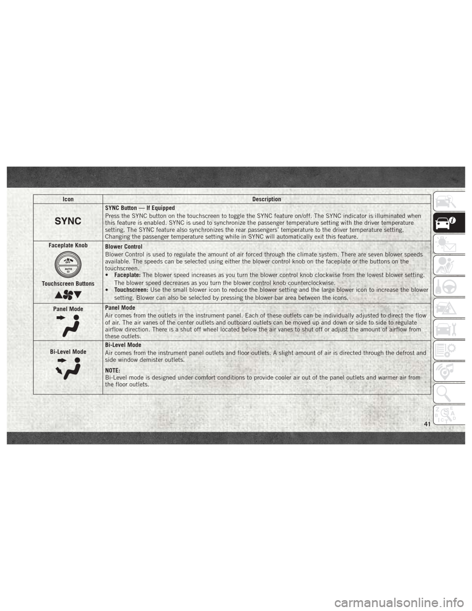
IconDescription
SYNC Button — If Equipped
Press the SYNC button on the touchscreen to toggle the SYNC feature on/off. The SYNC indicator is illuminated when
this feature is enabled. SYNC is used to synchronize the passenger temperature setting with the driver temperature
setting. The SYNC feature also synchronizes the rear passengers’ temperature to the driver temperature setting.
Changing the passenger temperature setting while in SYNC will automatically exit this feature.
Faceplate Knob
Touchscreen Buttons
Blower Control
Blower Control is used to regulate the amount of air forced through the climate system. There are seven blower speeds
available. The speeds can be selected using either the blower control knob on the faceplate or the buttons on the
touchscreen.
• Faceplate: The blower speed increases as you turn the blower control knob clockwise from the lowest blower setting.
The blower speed decreases as you turn the blower control knob counterclockwise.
• Touchscreen:
Use the small blower icon to reduce the blower setting and the large blower icon to increase the blower
setting. Blower can also be selected by pressing the blower bar area between the icons.
Panel Mode
Panel Mode
Air comes from the outlets in the instrument panel. Each of these outlets can be individually adjusted to direct the flow
of air. The air vanes of the center outlets and outboard outlets can be moved up and down or side to side to regulate
airflow direction. There is a shut off wheel located below the air vanes to shut off or adjust the amount of airflow from
these outlets.
Bi-Level Mode
Bi-Level Mode
Air comes from the instrument panel outlets and floor outlets. A slight amount of air is directed through the defrost and
side window demister outlets.
NOTE:
Bi-Level mode is designed under comfort conditions to provide cooler air out of the panel outlets and warmer air from
the floor outlets.
41
Page 47 of 298

1. Pull the hood release lever located belowthe steering wheel at the base of the
instrument panel.
2. Reach into the opening beneath the cen- ter of the hood and push the safety latch
lever to the left to release it, before raising
the hood.
To Close The Hood
Lower the hood to approximately 12 inches
(30 cm) from the engine compartment and
drop it. Make sure that the hood is completely
closed.
WARNING!
Be sure the hood is fully latched before
driving your vehicle. If the hood is not fully
latched, it could open when the vehicle is
in motion and block your vision. Failure to
follow this warning could result in serious
injury or death.
CAUTION!
To prevent possible damage, do not slam
the hood to close it. Use a firm downward
push at the front center of the hood to
ensure that both latches engage.
UNIVERSAL GARAGE DOOR OPENER
(HOMELINK)
• HomeLink replaces up to three hand-held
transmitters that operate devices such as
garage door openers, motorized gates,
lighting or home security systems. The
HomeLink unit is powered by your vehicles
12 Volt battery.
HomeLink Buttons
45