run flat RAM CHASSIS CAB 2020 Owners Manual
[x] Cancel search | Manufacturer: RAM, Model Year: 2020, Model line: CHASSIS CAB, Model: RAM CHASSIS CAB 2020Pages: 516, PDF Size: 16.57 MB
Page 78 of 516

76GETTING TO KNOW YOUR VEHICLE
Storage Bin (Regular Cab)
The storage bin is located behind the front
seats and runs the length of the cab.
Storage Bin
Fold Flat Load Floor — If Equipped
Crew Cab models with a 60/40 rear seat may
be equipped with a folding load floor. Unfolding The Load Floor/Crew Cab
1. Lift the 60/40 seat cushion(s) to the
upward position.
Load Floor Legs In Stowed Position
2. Unfold both the legs using the straps.
Load Floor Legs In Opened Position
3. Lift the front panel until the load floor
unfolds into position.
Load Floor In Open Position
4. Reverse the procedure to store the load floor.
Positioning The Load Floor For Storage Access
Under The Seat
1. Lift the 60/40 seat cushion(s) to the upward position.
2. Unsnap the securing snap located at either side of the load floor.
3. Lift the load floor up to access storage under the load floor.
WARNING!
Do not operate the vehicle with loose items
stored on the load floor. While driving or in an
accident you may experience abrupt stopping,
rapid acceleration, or sharp turns. Loose
objects stored on the load floor may move
around with force and strike occupants,
resulting in serious or fatal injury.
2020_RAM_CHASSIS_CAB_OM_USA=GUID-6C67832B-7839-4CCF-BEFC-CDF988F949EA=1=en=.book Page 76
Page 139 of 516

SAFETY137
Trailer Tire Pressure Sensor Pairing
In order use this feature, the provided tire pres -
sure sensors must be installed in the desired
trailer tires and the sensors must be paired to
the truck. If the target trailer requires more than
the provided four sensors, additional sensors
can be purchased at an authorized Ram dealer -
ship.
With the sensors installed and the trailer near
or connected to your Ram truck, initiate the
pairing process by entering the settings menu in
the radio and select trailer. Refer to “Uconnect
Settings” in “Multimedia” for further informa -
tion. Select the desired trailer profile to pair to,
open the “Tire Pressure” menu, and hit “Setup
All Tires.” Follow the on screen prompts to select the
number of axles (1 - 3), the number of trailer
tires (2, 4, 6, 8, or 12), and the set trailer tire
pressure. The range is selectable anywhere
between 25-125 PSI (172-862 kPa).
Once PSI (kPa) is programmed, the pairing
screen appears. Tire sensors must be paired in
order shown. Starting with Tire 1, deflate tire by
5 PSI (34 kPa) and wait for a horn chirp. It may
take up to three minutes for the chirp to occur,
indicating that the sensor has paired. Repeat
process on each tire, in order, until complete.
Do not exit the pairing screen until process is
complete. If pairing was unsuccessful, a double
horn chirp will sound, and a prompt on the touchscreen will allow you to retry the proce
-
dure; “Retry” will only appear when setup fails.
Each tire must be successfully paired during a
single pairing process to receive the success
screen.
NOTE:
If the pairing process times out after three
minutes of no communication with a sensor, a
double horn chirp will occur indicating the
pairing has failed and a message will display on
the radio indicating the process was unsuc -
cessful. Under certain circumstances, the
double horn chirp may continue to happen
every three minutes indicating the failed
pairing. If this happens, the horn chirping may
be canceled by cycling the ignition button OFF
and then back to ON/RUN position.
Tire Pres sure Monitoring Lo w Pre ssure
Warnings
When a tire pressure low in one or more of the
active road tires is detected, the instrument
cluster will display a message stating “Trailer
Tire Pressure Low”. The instrument cluster will
then display the TTPMS graphic showing the
pressure values of each tire with the low tire
pressure values in a different color.
4
2020_RAM_CHASSIS_CAB_OM_USA=GUID-6C67832B-7839-4CCF-BEFC-CDF988F949EA=1=en=.book Page 137
Page 140 of 516
138SAFETY
Should this occur, you should stop as soon as
possible and inflate the tires with a low pressure
condition (those in a different color in the instru -
ment cluster graphic) to the customer
programmed target tire pressure value as
shown at the top of the TTPMS instrument
cluster graphic. Once the tire(s) are inflated, the
system will automatically update the graphic
display in the instrument cluster, returning to
it’s original color. The vehicle may need to be
driven for up to 10 minutes above 15 mph
(24 km/h) in order for the TTPMS to receive the
updated information.
Service TTPMS Warning
If a system fault is detected, the instrument
cluster will display a “Trailer Tire Pressure
System Service Required” message for a
minimum of five seconds.
Once the system fault is corrected the "Trailer
Tire Pressure System Service Required"
message will no longer be displayed. The
vehicle may need to be driven for up to
10 minutes above 15 mph (24 km/h) in order
for the TTPMS to receive the trailer tire pressure
information. Trailer Tire Pressure System Not Configured
A “Trailer Tire Pressure System Not Configured”
message will be displayed in the Instrument
Cluster on the TTPM instrument cluster graphic
when a trailer number is selected that has not
had trailer tire pressure sensors paired. To
correct this condition, see “Trailer Tire Pressure
Sensor Pairing” in “Multimedia”.
Trailer Sensors Detected Do Not Match Active
Trailer
The “Trailer Sensors Detected Do Not Match
Active Trailer” message will be displayed in the
Instrument Cluster when the trailer sensors
being received by the TTPM module do not
match the trailer sensors paired to the current
trailer number selected. This message will be
displayed when the sensors being received
completely match the sensors paired to another
trailer number configured in the TTPM module.
To correct this condition, the correct trailer
number must be selected in the radio. Refer to
the “Uconnect Settings” in “Multimedia” for
further information.Tire Fill Alert — If Equipped
This feature notifies the user when the placard
tire pressure is attained while inflating or
deflating the tire.
The customer may choose to disable or enable
the Tire Fill Alert feature through use of the
customer settings in the radio.
NOTE:
Only one tire can be filled at a time when
using the Tire Fill Alert system.
The Tire Fill Alert feature cannot be entered if
an existing TPM system fault is set to “active”
or if the system is in deactivation mode (if
equipped).
The system will be activated when the TPM
receiver module detects a change in tire pres -
sure. The ignition must be in the RUN mode,
with the transmission in PARK (P).
NOTE:
It is not required to have the engine running to
enter Tire Fill Alert mode.
2020_RAM_CHASSIS_CAB_OM_USA=GUID-6C67832B-7839-4CCF-BEFC-CDF988F949EA=1=en=.book Page 138
Page 141 of 516
SAFETY139
The hazard lamps will come on to confirm the
vehicle is in Tire Fill Alert mode.
When Tire Fill Alert Mode is entered, the tire
pressure display screen will be displayed in the
instrument cluster.
Operation:
The horn will chirp once to let the user know
when to stop filling the tire, when it reaches
recommended pressure.
The horn will chirp three times if the tire is
over filled and will continue to chirp every five
seconds if the user continues to inflate the
tire.
The horn will chirp once again when enough
air is let out to reach proper inflation level.
The horn will also chirp three times if the tire
is then under-inflated and will continue to
chirp every five seconds if the user continues
to deflate the tire. Selectable Tire Fill Alert (STFA) — If Equipped
The Selectable Tire Fill Alert (STFA) system is an
optional feature that is included as part of the
normal Tire Fill Alert system. The system is
designed to allow the customer to select a pres
-
sure to inflate or deflate the vehicle's front and
rear axle tires to and to provide feedback to the
customer while inflating or deflating the
vehicle's tires.
In the Selectable Tire Fill Alert customer
settings menu in the radio, the customer will be
able to select a pressure setting for both the
front and rear axle tire pressures by scrolling
through a pressure range from XX to 15 psi in
1 psi increments for each axle setting. XX = the
vehicle’s cold placard pressure values for the
front and rear axles as shown on the vehicle
placard pressure label.
The customer may also store the pressure
values chosen for each axle in the radio as a
preset pressure. The customer will be allowed
to store up to two sets of preset values in the
radio for the front and rear axle pressure values.
Once the customer selects the tire pressures for
the front and rear axles that they want to inflate
or deflate to, they can begin inflating or
deflating one tire at a time. NOTE:
The STFA system will only support inflating or
deflating one tire at a time.
The system will be activated when the TPM
receiver module detects a change in tire pres
-
sure. The ignition must be in the RUN mode,
with the transmission in PARK (P).
The hazard lamps will come on to confirm the
vehicle is in Tire Fill Alert mode.
When Tire Fill Alert Mode is entered, the tire
pressure display screen will be displayed in the
instrument cluster.
Operation:
The horn will chirp once when the selected
pressure is reached to let the user know
when to stop inflating or deflating the tire.
The horn will chirp three times if the tire is
over inflated or over deflated and will
continue to chirp every five seconds if the
user continues to inflate or deflate the tire.
The horn will chirp once again when enough
air is added or removed to reach proper
selected pressure level.
4
2020_RAM_CHASSIS_CAB_OM_USA=GUID-6C67832B-7839-4CCF-BEFC-CDF988F949EA=1=en=.book Page 139
Page 153 of 516
SAFETY151
Supplemental Restraint Systems (SRS)
Some of the safety features described in this
section may be standard equipment on some
models, or may be optional equipment on
others. If you are not sure, ask an authorized
dealer.
The air bag system must be ready to protect you
in a collision. The Occupant Restraint Controller
(ORC) monitors the internal circuits and inter -
connecting wiring associated with the electrical
Air Bag System Components. Your vehicle may
be equipped with the following Air Bag System
Components:
Air Bag System Components
Occupant Restraint Controller (ORC)
Air Bag Warning Light
Steering Wheel and Column
Instrument Panel
Knee Impact Bolsters
Driver and Front Passenger Air Bags
Seat Belt Buckle Switch
Supplemental Side Air Bags — If Equipped
Front and Side Impact Sensors — If Equipped
Seat Belt Pretensioners — If Equipped
Air Bag Warning Light
The ORC monitors the readiness of
the electronic parts of the air bag
system whenever the ignition switch
is in the START or ON/RUN position. If
the ignition switch is in the OFF position or in the
ACC position, the air bag system is not on and
the air bags will not inflate.
The ORC contains a backup power supply
system that may deploy the air bag system even
if the battery loses power or it becomes discon -
nected prior to deployment.
The ORC turns on the Air Bag Warning Light in
the instrument panel for approximately four to
eight seconds for a self-check when the ignition
switch is first in the ON/RUN position. After the
self-check, the Air Bag Warning Light will turn
off. If the ORC detects a malfunction in any part
of the system, it turns on the Air Bag Warning
Light, either momentarily or continuously. A
single chime will sound to alert you if the light
comes on again after initial startup. The ORC also includes diagnostics that will illu-
minate the instrument panel Air Bag Warning
Light if a malfunction is detected that could
affect the air bag system. The diagnostics also
record the nature of the malfunction. While the
air bag system is designed to be maintenance
free, if any of the following occurs, have an
authorized dealer service the air bag system
immediately.
The Air Bag Warning Light does not come on
during the four to eight seconds when the
ignition switch is first in the ON/RUN position.
The Air Bag Warning Light remains on after
the four to eight-second interval.
The Air Bag Warning Light comes on intermit
-
tently or remains on while driving.
NOTE:
If the speedometer, tachometer, or any engine
related gauges are not working, the Occupant
Restraint Controller (ORC) may also be
disabled. In this condition the air bags may not
be ready to inflate for your protection. Have an
authorized dealer service the air bag system
immediately.
4
2020_RAM_CHASSIS_CAB_OM_USA=GUID-6C67832B-7839-4CCF-BEFC-CDF988F949EA=1=en=.book Page 151
Page 328 of 516

326IN CASE OF EMERGENCY
TOWING A DISABLED VEHICLE
This section describes procedures for towing a disabled vehicle using a commercial towing service. If the transmission and drivetrain are operable,
disabled vehicles may also be towed as described under “Recreational Towing” in the “Starting And Operating” section.
Proper towing or lifting equipment is required to
prevent damage to your vehicle. Use only tow
bars and other equipment designed for this
purpose, following equipment manufacturer’s
instructions. Use of safety chains is mandatory.
Attach a tow bar or other towing device to main
structural members of the vehicle, not to
bumpers or associated brackets. State and
local laws regarding vehicles under tow must be
observed. If you must use the accessories (wipers,
defrosters, etc.) while being towed, the ignition
must be in the ON/RUN mode, not the ACC
mode.
If the key fob is unavailable or the vehicle's
battery is discharged, refer to “Manual Park
Release” or “Gear Selector Override” in this
section for instructions on shifting the auto
-
matic transmission out of PARK for towing.
Towing Condition Wheels OFF The
Ground 2WD Models
4WD Models
Flat Tow NONE If transmission is operable:
• Transmission in NEUTRAL
• 30 mph (48 km/h) max speed
• 15 miles (24 km) max distance (6–speed
transmission)
• 30 miles (48 km) max distance (8–speed
transmission) See instructions in “Recreational Towing” under
“Starting And Operating”
• Auto Transmission in PARK
• Transfer Case in NEUTRAL
• Tow in forward direction
Wheel Lift Or Dolly Tow Front
NOT ALLOWED
Rear OK NOT ALLOWED
Flatbed ALL
BEST METHOD BEST METHOD
CAUTION!
Do not use sling type equipment when
towing. Vehicle damage may occur.
When securing the vehicle to a flat bed
truck, do not attach to front or rear suspen-
sion components. Damage to your vehicle
may result from improper towing.
2020_RAM_CHASSIS_CAB_OM_USA=GUID-6C67832B-7839-4CCF-BEFC-CDF988F949EA=1=en=.book Page 326
Page 331 of 516
329
SERVICING AND MAINTENANCE
SCHEDULED SERVICING — GAS ENGINE
Your vehicle is equipped with an automatic oil
change indicator system. The oil change indi-
cator system will remind you that it is time to
take your vehicle in for scheduled maintenance.
Based on engine operation conditions, the oil
change indicator message will illuminate. This
means that service is required for your vehicle.
Operating conditions such as frequent
short-trips, trailer tow, extremely hot or cold
ambient temperatures, and E85 fuel usage will
influence when the “Oil Change Required”
message is displayed. Severe Operating Condi-
tions can cause the change oil message to illu -
minate as early as 3,500 miles (5,600 km)
since last reset. Have your vehicle serviced as
soon as possible, within the next 500 miles
(805 km). An authorized dealer will reset the oil change
indicator message after completing the sched
-
uled oil change. If a scheduled oil change is
performed by someone other than an autho -
rized dealer, the message can be reset by refer -
ring to the steps described under “Instrument
Cluster Display” in “Getting To Know Your
Instrument Panel” for further information.
Gas Engines:
Under no circumstances should oil change
intervals exceed 8,000 miles (13,000 km),
12 months or 350 hours of engine run time,
whichever comes first. The 350 hours of engine
run or idle time is generally only a concern for
fleet customers.
Severe Duty:
Change Engine Oil at 4,000 miles (6,500 km) or
350 hours of engine run time if the vehicle is
operated in a dusty and off road environment or
is operated predominately at idle or very low
engine RPM. This type of vehicle use is consid -
ered Severe Duty. Once A Month Or Before A Long Trip:Check engine oil level.
Check windshield washer fluid level.
Check the tire inflation pressures and look
for unusual wear or damage. Rotate at the
first sign of irregular wear.
Check the fluid levels of the coolant reservoir,
brake master cylinder, power steering and
automatic transmission (six-speed only), and
fill as needed.
Check function of all interior and exterior
lights.
7
2020_RAM_CHASSIS_CAB_OM_USA=GUID-6C67832B-7839-4CCF-BEFC-CDF988F949EA=1=en=.book Page 329
Page 386 of 516

384SERVICING AND MAINTENANCE
Radial Ply Tires
Tire Repair
If your tire becomes damaged, it may be
repaired if it meets the following criteria:
The tire has not been driven on when flat.
The damage is only on the tread section of
your tire (sidewall damage is not repairable).
The puncture is no greater than a ¼ of an
inch (6 mm).
Consult an authorized tire dealer for tire repairs
and additional information. Damaged Run Flat tires, or Run Flat tires that
have experienced a loss of pressure should be
replaced immediately with another Run Flat tire
of identical size and service description (Load
Index and Speed Symbol). Replace the tire pres
-
sure sensor as well as it is not designed to be
reused.
Run Flat Tires — If Equipped
Run Flat tires allow you the capability to drive
50 miles (80 km) at 50 mph (80 km/h) after a
rapid loss of inflation pressure. This rapid loss
of inflation is referred to as the Run Flat mode.
A Run Flat mode occurs when the tire inflation
pressure is of/or below 14 psi (96 kPa). Once a
Run Flat tire reaches the run flat mode it has
limited driving capabilities and needs to be
replaced immediately. A Run Flat tire is not
repairable. When a run flat tire is changed after
driving with underinflated tire condition, please
replace the TPM sensor as it is not designed to
be reused when driven under run flat mode
14 psi (96 kPa) condition. NOTE:
TPM Sensor must be replaced after driving the
vehicle on a flat tire condition.
It is not recommended driving a vehicle loaded
at full capacity or to tow a trailer while a tire is in
the run flat mode.
See the tire pressure monitoring section for
more information.Tire Spinning
When stuck in mud, sand, snow, or ice condi
-
tions, do not spin your vehicle's wheels above
30 mph (48 km/h) or for longer than 30
seconds continuously without stopping.
Refer to “Freeing A Stuck Vehicle” in “In Case Of
Emergency” for further information.
WARNING!
Combining radial ply tires with other types of
tires on your vehicle will cause your vehicle to
handle poorly. The instability could cause a
collision. Always use radial ply tires in sets of
four. Never combine them with other types of
tires.
WARNING!
Fast spinning tires can be dangerous. Forces
generated by excessive wheel speeds may
cause tire damage or failure. A tire could
explode and injure someone. Do not spin your
vehicle's wheels faster than 30 mph
(48 km/h) for more than 30 seconds
continuously when you are stuck, and do not
let anyone near a spinning wheel, no matter
what the speed.
2020_RAM_CHASSIS_CAB_OM_USA=GUID-6C67832B-7839-4CCF-BEFC-CDF988F949EA=1=en=.book Page 384
Page 395 of 516

SERVICING AND MAINTENANCE393
Temperature Grades
The Temperature grades are A (the
highest), B, and C, representing the tire's
resistance to the generation of heat and
its ability to dissipate heat, when tested
under controlled conditions on a speci -
fied indoor laboratory test wheel.
Sustained high temperature can cause
the material of the tire to degenerate
and reduce tire life, and excessive
temperature can lead to sudden tire
failure. The grade C corresponds to a
level of performance, which all
passenger vehicle tires must meet
under the Federal Motor Vehicle Safety
Standard No. 109. Grades B and A repre -sent higher levels of performance on the
laboratory test wheel, than the minimum
required by law.
STORING THE VEHICLE
If you are storing your vehicle for more than 21
days, we recommend that you take the following
steps to minimize the drain on your vehicle's
battery:
Disconnect the negative cable from battery.
Any time you store your vehicle or keep it out
of service (i.e., vacation) for two weeks or
more, run the air conditioning system at idle
for about five minutes in the fresh air and
high blower setting. This will ensure
adequate system lubrication to minimize the
possibility of compressor damage when the
system is started again.
BODYWORK
Protection From Atmospheric Agents
Vehicle body care requirements vary according
to geographic locations and usage. Chemicals
that make roads passable in snow and ice and
those that are sprayed on trees and road
surfaces during other seasons are highly corro
-
sive to the metal in your vehicle. Outside
parking, which exposes your vehicle to airborne
contaminants, road surfaces on which the
vehicle is operated, extreme hot or cold weather
and other extreme conditions will have an
adverse effect on paint, metal trim, and under -
body protection.
The following maintenance recommendations
will enable you to obtain maximum benefit from
the corrosion resistance built into your vehicle.
WARNING!
The traction grade assigned to this tire is
based on straight-ahead braking traction
tests, and does not include acceleration,
cornering, hydroplaning, or peak traction
characteristics.
WARNING!
The temperature grade for this tire is
established for a tire that is properly inflated
and not overloaded. Excessive speed,
under-inflation, or excessive loading, either
separately or in combination, can cause heat
buildup and possible tire failure.
7
2020_RAM_CHASSIS_CAB_OM_USA=GUID-6C67832B-7839-4CCF-BEFC-CDF988F949EA=1=en=.book Page 393
Page 507 of 516
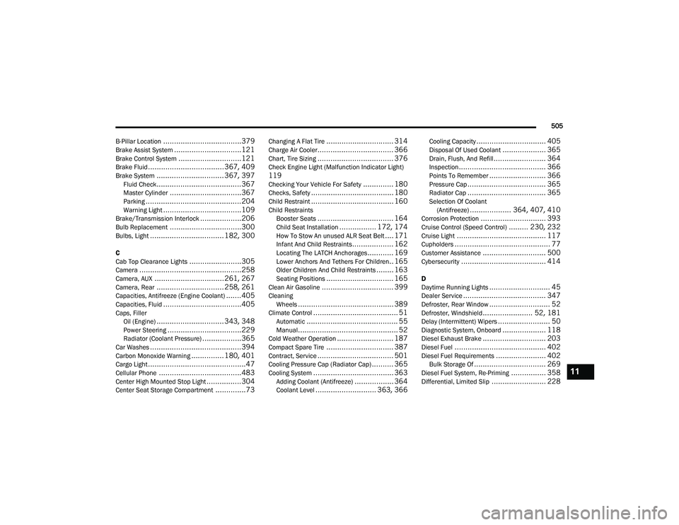
505
B-Pillar Location
....................................379Brake Assist System...............................121Brake Control System.............................121Brake Fluid...................................367, 409Brake System............................... 367, 397Fluid Check.......................................367Master Cylinder.................................367Parking............................................204Warning Light....................................109Brake/Transmission Interlock...................206Bulb Replacement.................................300Bulbs, Light.................................. 182, 300
C
Cab Top Clearance Lights........................305Camera...............................................258Camera, AUX................................ 261, 267Camera, Rear............................... 258, 261Capacities, Antifreeze (Engine Coolant).......405Capacities, Fluid....................................405Caps, Filler Oil (Engine)............................... 343, 348Power Steering..................................229Radiator (Coolant Pressure)..................365Car Washes..........................................394Carbon Monoxide Warning............... 180, 401Cargo Light.............................................47Cellular Phone......................................483Center High Mounted Stop Light................304Center Seat Storage Compartment..............73
Changing A Flat Tire............................... 314Charge Air Cooler................................... 366Chart, Tire Sizing................................... 376Check Engine Light (Malfunction Indicator Light)119Checking Your Vehicle For Safety.............. 180Checks, Safety...................................... 180Child Restraint...................................... 160Child RestraintsBooster Seats................................... 164Child Seat Installation................. 172, 174How To Stow An unused ALR Seat Belt.... 171Infant And Child Restraints................... 162Locating The LATCH Anchorages............ 169Lower Anchors And Tethers For Children.. 165Older Children And Child Restraints........ 163Seating Positions............................... 165Clean Air Gasoline................................. 399CleaningWheels............................................ 389Climate Control....................................... 51Automatic.......................................... 55Manual.............................................. 52Cold Weather Operation.......................... 187Compact Spare Tire............................... 387Contract, Service................................... 501Cooling Pressure Cap (Radiator Cap).......... 365Cooling System..................................... 363Adding Coolant (Antifreeze).................. 364Coolant Level............................ 363, 366
Cooling Capacity................................ 405Disposal Of Used Coolant.................... 365Drain, Flush, And Refill........................ 364Inspection........................................ 366Points To Remember.......................... 366Pressure Cap.................................... 365Radiator Cap.................................... 365Selection Of Coolant(Antifreeze)................... 364, 407, 410Corrosion Protection.............................. 393Cruise Control (Speed Control)......... 230, 232Cruise Light......................................... 117Cupholders............................................ 77Customer Assistance............................. 500Cybersecurity....................................... 414
D
Daytime Running Lights............................ 45Dealer Service...................................... 347Defroster, Rear Window............................ 52Defroster, Windshield....................... 52, 181Delay (Intermittent) Wipers........................ 50Diagnostic System, Onboard.................... 118Diesel Exhaust Brake............................. 203Diesel Fuel.......................................... 402Diesel Fuel Requirements....................... 402Bulk Storage Of................................. 269Diesel Fuel System, Re-Priming................ 358Differential, Limited Slip......................... 228
11
2020_RAM_CHASSIS_CAB_OM_USA=GUID-6C67832B-7839-4CCF-BEFC-CDF988F949EA=1=en=.book Page 505