brake fluid RAM CHASSIS CAB 2022 Owners Manual
[x] Cancel search | Manufacturer: RAM, Model Year: 2022, Model line: CHASSIS CAB, Model: RAM CHASSIS CAB 2022Pages: 428, PDF Size: 20.18 MB
Page 6 of 428
4
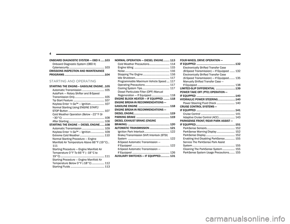
ONBOARD DIAGNOSTIC SYSTEM — OBD II ...... 103 Onboard Diagnostic System (OBD II)
Cybersecurity ................................................. 103
EMISSIONS INSPECTION AND MAINTENANCE
PROGRAMS .......................................................... 104
STARTING AND OPERATING
STARTING THE ENGINE— GASOLINE ENGINE .. 105
Automatic Transmission ............................... 105
AutoPark — Rotary Shifter and 8-Speed
Transmission Only ......................................... 105
Tip Start Feature ........................................... 107Keyless Enter ‘n Go™ — Ignition................... 107
Normal Starting Using ENGINE START/
STOP Button .................................................. 107
Cold Weather Operation (Below –22°F Or
−30°C) .......................................................... 108
After Starting.................................................. 108
STARTING THE ENGINE — DIESEL ENGINE....... 108
Automatic Transmission ............................... 109
Keyless Enter ‘n Go™ — Ignition................... 109
Extreme Cold Weather .................................. 110
Normal Starting Procedure — Engine
Manifold Air Temperature Above 66°F (19°C) ..
111
Starting Procedure — Engine Manifold Air
Temperature 0°F To 66°F (–18°C to
19°C) ............................................................. 111
Starting Procedure — Engine Manifold Air
Temperature Below 0°F (-18°C) ................. 112Starting Fluids ............................................... 113 NORMAL OPERATION — DIESEL ENGINE ......... 113
Cold Weather Precautions ............................ 114
Engine Idling ................................................. 115
Noise .............................................................. 116
Stopping The Engine ..................................... 116
Idle Shutdown................................................ 117Programmable Maximum Vehicle Speed .... 117
Operating Precautions .................................. 117
Cooling System Tips ...................................... 117
Diesel Particulate Filter (DPF) Manual
Regeneration — If Equipped ......................... 118
ENGINE BLOCK HEATER — IF EQUIPPED ......... 118
ENGINE BREAK-IN RECOMMENDATIONS —
GASOLINE ENGINE ............................................. 118
ENGINE BREAK-IN RECOMMENDATIONS —
DIESEL ENGINE.................................................... 119
PARKING BRAKE ................................................ 119
DIESEL EXHAUST BRAKE (ENGINE
BRAKING) ............................................................ 120
AUTOMATIC TRANSMISSION ............................. 121 Ignition Park Interlock ................................... 122Brake/Transmission Shift Interlock (BTSI)
System .......................................................... 1228-Speed Automatic Transmission —
If Equipped .................................................... 122
6-Speed Automatic Transmission —
If Equipped .................................................... 126
AUXILIARY SWITCHES — IF EQUIPPED............. 131 FOUR-WHEEL DRIVE OPERATION —
IF EQUIPPED ........................................................ 132
Electronically Shifted Transfer Case
(8-Speed Transmission) — If Equipped ....... 132
Electronically Shifted Transfer Case
(6-Speed Transmission) — If Equipped ........ 135Manually Shifted Transfer Case —
If Equipped .................................................... 138
LIMITED-SLIP DIFFERENTIAL ............................ 139
POWER TAKE OFF (PTO) OPERATION —
IF EQUIPPED ........................................................ 140
HYDRAULIC POWER STEERING ......................... 140
Power Steering Fluid Check ......................... 140
CRUISE CONTROL SYSTEMS —
IF EQUIPPED ........................................................ 141
Cruise Control ............................................... 141Adaptive Cruise Control (ACC) ...................... 143
PARKSENSE FRONT/REAR PARK ASSIST —
IF EQUIPPED ......................................................... 151
ParkSense Sensors ....................................... 152
ParkSense Warning Display ......................... 152
ParkSense Display ........................................ 152
Enabling And Disabling ParkSense.............. 155
Service The ParkSense Park Assist
System ........................................................... 155
Cleaning The ParkSense System ................. 155
ParkSense System Usage Precautions........ 155
22_DPF_OM_EN_USC_t.book Page 4
Page 9 of 428
7
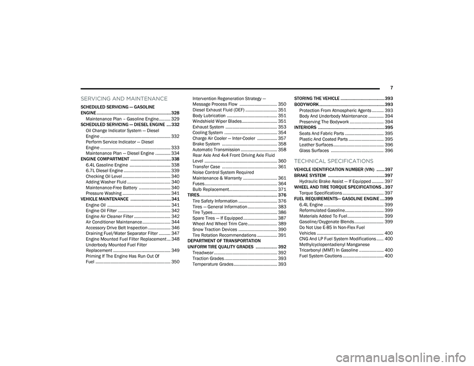
SERVICING AND MAINTENANCE
SCHEDULED SERVICING — GASOLINE
ENGINE .................................................................. 328Maintenance Plan – Gasoline Engine.......... 329
SCHEDULED SERVICING — DIESEL ENGINE .... 332
Oil Change Indicator System — Diesel
Engine ............................................................ 332
Perform Service Indicator — Diesel
Engine ............................................................ 333
Maintenance Plan — Diesel Engine ............. 334
ENGINE COMPARTMENT .................................... 338
6.4L Gasoline Engine ................................... 3386.7L Diesel Engine ........................................ 339
Checking Oil Level ......................................... 340
Adding Washer Fluid ..................................... 340
Maintenance-Free Battery ........................... 340
Pressure Washing ......................................... 341
VEHICLE MAINTENANCE .................................... 341
Engine Oil ...................................................... 341Engine Oil Filter ............................................. 342
Engine Air Cleaner Filter ............................... 342
Air Conditioner Maintenance ........................ 344
Accessory Drive Belt Inspection ................... 346
Draining Fuel/Water Separator Filter .......... 347
Engine Mounted Fuel Filter Replacement ... 348
Underbody Mounted Fuel Filter
Replacement ................................................. 349
Priming If The Engine Has Run Out Of
Fuel ................................................................ 350 Intervention Regeneration Strategy —
Message Process Flow ................................ 350
Diesel Exhaust Fluid (DEF) ........................... 351Body Lubrication ........................................... 351Windshield Wiper Blades.............................. 351Exhaust System ............................................ 353
Cooling System ............................................. 354Charge Air Cooler — Inter-Cooler ................. 357
Brake System ............................................... 358
Automatic Transmission ............................... 358
Rear Axle And 4x4 Front Driving Axle Fluid
Level .............................................................. 360
Transfer Case ............................................... 361
Noise Control System Required
Maintenance & Warranty ............................. 361
Fuses.............................................................. 364
Bulb Replacement......................................... 371
TIRES..................................................................... 376
Tire Safety Information ................................. 376
Tires — General Information ......................... 383
Tire Types....................................................... 386
Spare Tires — If Equipped ............................. 387
Wheel And Wheel Trim Care ......................... 389
Snow Traction Devices ................................. 390
Tire Rotation Recommendations ................. 391
DEPARTMENT OF TRANSPORTATION
UNIFORM TIRE QUALITY GRADES ................... 392
Treadwear ...................................................... 392
Traction Grades ............................................. 393Temperature Grades ..................................... 393 STORING THE VEHICLE ....................................... 393
BODYWORK .......................................................... 393
Protection From Atmospheric Agents .......... 393
Body And Underbody Maintenance ............. 394
Preserving The Bodywork ............................. 394
INTERIORS ........................................................... 395
Seats And Fabric Parts ................................. 395
Plastic And Coated Parts .............................. 395
Leather Surfaces........................................... 396
Glass Surfaces ............................................. 396
TECHNICAL SPECIFICATIONS
VEHICLE IDENTIFICATION NUMBER (VIN) ....... 397
BRAKE SYSTEM .................................................. 397Hydraulic Brake Assist — If Equipped .......... 397
WHEEL AND TIRE TORQUE SPECIFICATIONS .. 397
Torque Specifications ................................... 397
FUEL REQUIREMENTS— GASOLINE ENGINE .... 399
6.4L Engine ................................................... 399
Reformulated Gasoline................................. 399
Materials Added To Fuel ............................... 399
Gasoline/Oxygenate Blends ......................... 399
Do Not Use E-85 In Non-Flex Fuel
Vehicles ......................................................... 400
CNG And LP Fuel System Modifications ...... 400Methylcyclopentadienyl Manganese
Tricarbonyl (MMT) In Gasoline ..................... 400Fuel System Cautions ................................... 400
22_DPF_OM_EN_USC_t.book Page 7
Page 14 of 428
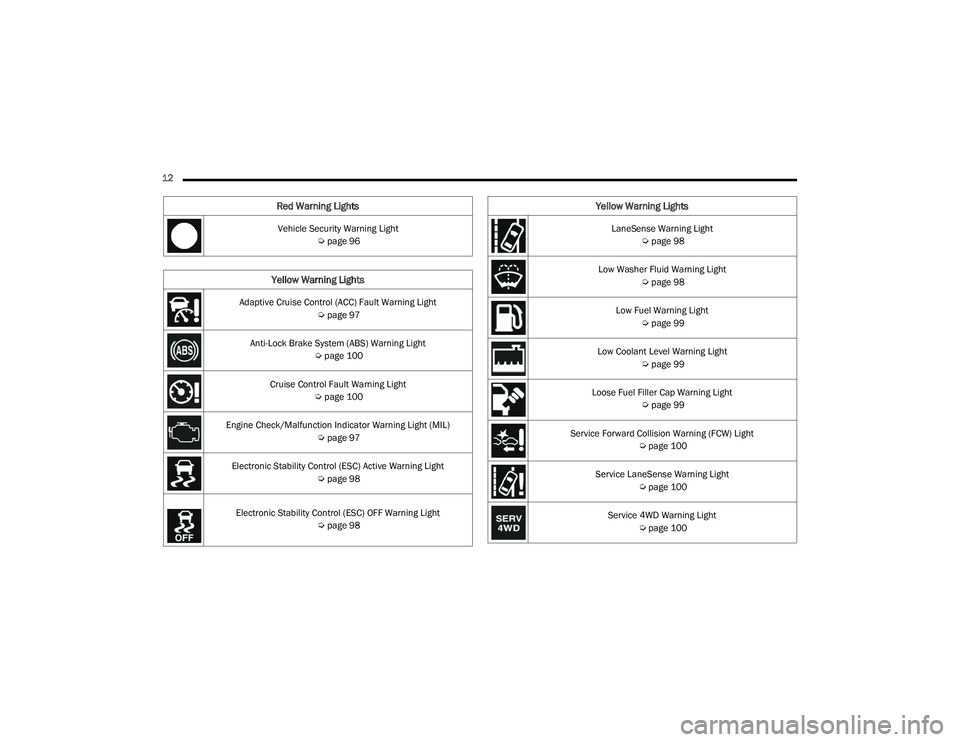
12 Vehicle Security Warning Light Úpage 96
Yellow Warning Lights
Adaptive Cruise Control (ACC) Fault Warning Light
Úpage 97
Anti-Lock Brake System (ABS) Warning Light Úpage 100
Cruise Control Fault Warning Light Úpage 100
Engine Check/Malfunction Indicator Warning Light (MIL) Úpage 97
Electronic Stability Control (ESC) Active Warning Light Úpage 98
Electronic Stability Control (ESC) OFF Warning Light
Úpage 98
Red Warning Lights
LaneSense Warning Light
Úpage 98
Low Washer Fluid Warning Light Úpage 98
Low Fuel Warning Light Úpage 99
Low Coolant Level Warning Light Úpage 99
Loose Fuel Filler Cap Warning Light Úpage 99
Service Forward Collision Warning (FCW) Light Úpage 100
Service LaneSense Warning Light Úpage 100
Service 4WD Warning Light Úpage 100
Yellow Warning Lights
22_DPF_OM_EN_USC_t.book Page 12
Page 15 of 428
13
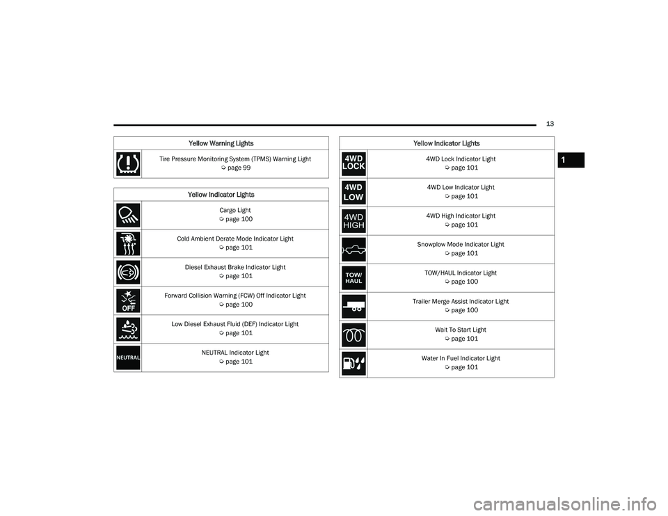
Tire Pressure Monitoring System (TPMS) Warning Light Úpage 99
Yellow Indicator Lights
Cargo Light
Ú page 100
Cold Ambient Derate Mode Indicator Light Úpage 101
Diesel Exhaust Brake Indicator Light Úpage 101
Forward Collision Warning (FCW) Off Indicator Light Úpage 100
Low Diesel Exhaust Fluid (DEF) Indicator Light Úpage 101
NEUTRAL Indicator Light Úpage 101
Yellow Warning Lights
4WD Lock Indicator Light
Úpage 101
4WD Low Indicator Light Úpage 101
4WD High Indicator Light Úpage 101
Snowplow Mode Indicator Light Úpage 101
TOW/HAUL Indicator Light Úpage 100
Trailer Merge Assist Indicator Light Úpage 100
Wait To Start Light Úpage 101
Water In Fuel Indicator Light Úpage 101
Yellow Indicator Lights
1
22_DPF_OM_EN_USC_t.book Page 13
Page 97 of 428

GETTING TO KNOW YOUR INSTRUMENT PANEL95
Air Bag Warning Light
This warning light will illuminate to
indicate a fault with the air bag, and will
turn on for four to eight seconds as a bulb
check when the ignition is placed in the
ON/RUN or ACC/ON/RUN position. This light will
illuminate with a single chime when a fault with the
air bag has been detected, it will stay on until the
fault is cleared. If the light is not on during startup,
stays on, or turns on while driving, have the system
inspected at an authorized dealer as soon as
possible.
Brake Warning Light
This warning light monitors various brake
functions, including brake fluid level and
parking brake application. If the brake
light turns on it may indicate that the
parking brake is applied, that the brake fluid level
is low, or that there is a problem with the Anti-Lock
Brake System reservoir.
If the light remains on when the parking brake has
been disengaged, and the fluid level is at the full
mark on the master cylinder reservoir, it indicates
a possible brake hydraulic system malfunction or
that a problem with the Brake Booster has been
detected by the Anti-Lock Brake System (ABS) /
Electronic Stability Control (ESC) system. In this
case, the light will remain on until the condition has been corrected. If the problem is related to the
brake booster, the ABS pump will run when
applying the brake, and a brake pedal pulsation
may be felt during each stop.
The dual brake system provides a reserve braking
capacity in the event of a failure to a portion of the
hydraulic system. A leak in either half of the dual
brake system is indicated by the Brake Warning
Light, which will turn on when the brake fluid level
in the master cylinder has dropped below a
specified level.
The light will remain on until the cause is corrected.
NOTE:The light may flash momentarily during sharp
cornering maneuvers, which change fluid level
conditions. The vehicle should have service
performed, and the brake fluid level checked.
If brake failure is indicated, immediate repair is
necessary.
Vehicles equipped with the Anti-Lock Brake System
(ABS) are also equipped with Electronic Brake
Force Distribution (EBD). In the event of an EBD
failure, the Brake Warning Light will turn on along
with the ABS Light. Immediate repair to the ABS
system is required.
Operation of the Brake Warning Light can be
checked by turning the ignition switch from the OFF
position to the ON/RUN position. The light should
illuminate for approximately two seconds. The light
should then turn off unless the parking brake is
applied or a brake fault is detected. If the light does
not illuminate, have the light inspected by an
authorized dealer.
The light also will turn on when the parking brake
is applied with the ignition switch in the ON/RUN
position.
NOTE:This light shows only that the parking brake is
applied. It does not show the degree of brake appli
-
cation.
Hood Open Warning Light
This warning light will illuminate when the
hood is ajar/open and not fully closed.
NOTE:If the vehicle is moving, there will also be a single
chime.
WARNING!
Driving a vehicle with the red brake light on is
dangerous. Part of the brake system may have
failed. It will take longer to stop the vehicle. You
could have a collision. Have the vehicle checked
immediately.
3
22_DPF_OM_EN_USC_t.book Page 95
Page 99 of 428
GETTING TO KNOW YOUR INSTRUMENT PANEL97
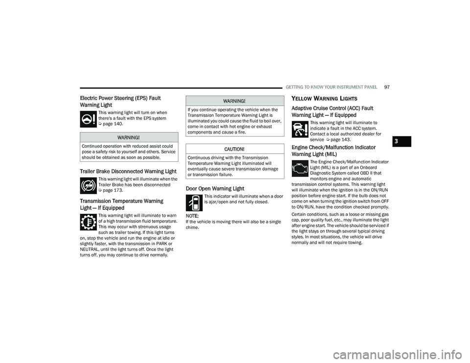
Electric Power Steering (EPS) Fault
Warning Light
This warning light will turn on when
there's a fault with the EPS system
Úpage 140.
Trailer Brake Disconnected Warning Light
This warning light will illuminate when the
Trailer Brake has been disconnected
Úpage 173.
Transmission Temperature Warning
Light — If Equipped
This warning light will illuminate to warn
of a high transmission fluid temperature.
This may occur with strenuous usage
such as trailer towing. If this light turns
on, stop the vehicle and run the engine at idle or
slightly faster, with the transmission in PARK or
NEUTRAL, until the light turns off. Once the light
turns off, you may continue to drive normally.
Door Open Warning Light
This indicator will illuminate when a door
is ajar/open and not fully closed.
NOTE:If the vehicle is moving there will also be a single
chime.
YELLOW WARNING LIGHTS
Adaptive Cruise Control (ACC) Fault
Warning Light — If Equipped
This warning light will illuminate to
indicate a fault in the ACC system.
Contact a local authorized dealer for
service Ú page 143.
Engine Check/Malfunction Indicator
Warning Light (MIL)
The Engine Check/Malfunction Indicator
Light (MIL) is a part of an Onboard
Diagnostic System called OBD II that
monitors engine and automatic
transmission control systems. This warning light
will illuminate when the ignition is in the ON/RUN
position before engine start. If the bulb does not
come on when turning the ignition switch from OFF
to ON/RUN, have the condition checked promptly.
Certain conditions, such as a loose or missing gas
cap, poor quality fuel, etc., may illuminate the light
after engine start. The vehicle should be serviced if
the light stays on through several typical driving
styles. In most situations, the vehicle will drive
normally and will not require towing.
WARNING!
Continued operation with reduced assist could
pose a safety risk to yourself and others. Service
should be obtained as soon as possible.
WARNING!
If you continue operating the vehicle when the
Transmission Temperature Warning Light is
illuminated you could cause the fluid to boil over,
come in contact with hot engine or exhaust
components and cause a fire.
CAUTION!
Continuous driving with the Transmission
Temperature Warning Light illuminated will
eventually cause severe transmission damage
or transmission failure.
3
22_DPF_OM_EN_USC_t.book Page 97
Page 103 of 428

GETTING TO KNOW YOUR INSTRUMENT PANEL101
Snowplow Mode Indicator Light —
If Equipped
This indicator light will illuminate when
Snowplow Mode has been activated
Úpage 183.
Cold Ambient Derate Mode Indicator
Light — If Equipped
This indicator light will illuminate when a
derate (engine power reduction) is
activated for protection of the turbo-
charger in cold ambient temperatures.
Diesel Exhaust Brake Indicator Light —
If Equipped
This indicator light will illuminate when
the Diesel Exhaust Brake has been
activated, and is in full strength mode
Úpage 120.
4WD Lock Indicator Light
This light alerts the driver that the vehicle
is in the 4WD LOCK mode. The front and
rear driveshafts are mechanically locked
together, forcing the front and rear
wheels to rotate at the same speed Ú page 132.
4WD Low Indicator Light — If Equipped
This light alerts the driver that the vehicle
is in the 4WD Low mode. The front and
rear driveshafts are mechanically locked together forcing the front and rear wheels to rotate
at the same speed. Low range provides a greater
gear reduction ratio to provide increased torque at
the wheels Ú
page 132.
4WD High Indicator Light — If Equipped
This light alerts the driver that the vehicle
is in the 4WD High mode. The front and
rear driveshafts are mechanically locked
together forcing the front and rear
wheels to rotate at the same speed.
NEUTRAL Indicator Light — If Equipped
This light alerts the driver that the 4WD
power transfer case is in the NEUTRAL
mode and the front and rear driveshafts
are disengaged from the powertrain.
Low Diesel Exhaust Fluid (DEF) Indicator
Light — If Equipped
The Low DEF Indicator will illuminate if
the vehicle is low on DEF Ú page 351.
Wait To Start Light — If Equipped
This indicator light will illuminate for
approximately two seconds when the
ignition is turned to the RUN position. Its
duration may be longer based on colder
operating conditions. Vehicle will not initiate start
until telltale is no longer displayed Ú page 108.
NOTE:The Wait To Start Light may not illuminate if the
intake manifold temperature is warm enough.
Water In Fuel Indicator Light — If Equipped
The Water In Fuel Indicator Light will
illuminate when there is water detected
in the fuel filter. If this light remains on,
DO NOT start the vehicle before you drain
the water from the fuel filter to prevent engine
damage Ú page 347.
GREEN INDICATOR LIGHTS
Adaptive Cruise Control (ACC) Set With
Target Light — If Equipped
This will display when the ACC is set and
a the vehicle in front is detected
Úpage 143.
Adaptive Cruise Control (ACC) Set With No
Target Detected Indicator Light —
If Equipped
This light will turn on when the Adaptive
Cruise Control is SET and there is no
vehicle in front detected Ú page 143.
3
22_DPF_OM_EN_USC_t.book Page 101
Page 115 of 428

STARTING AND OPERATING113
STARTING FLUIDS
The engine is equipped with an automatic electric
air preheating system. If the instructions in this
manual are followed, the engine should start in all
conditions.
NORMAL OPERATION — DIESEL ENGINE
Observe the following when the engine is
operating.
All message center lights are off.
Malfunction Indicator Light (MIL) is off.
Engine oil pressure is above 10 psi (69 kPa) at
idle.
Voltmeter operation:
The voltmeter may show a gauge fluctuation at
various engine temperatures. This cycling
operation is caused by the post-heat cycle of the
intake manifold heater system. The number of
cycles and the length of the cycling operation is
controlled by the engine control module. Post-heat
operation can run for several minutes, and then
the electrical system and voltmeter needle will
stabilize.
The cycling action will cause temporary dimming of
the headlamps, interior lamps, and also a
noticeable reduction in blower motor speed.
WARNING!
Starting fluids or flammable liquids must never
be used in the Cummins® diesel engine (see
Warning label). Never pour diesel fuel,
flammable liquid, starting fluids (ether) into the
air cleaner canister, air intake piping, or
turbocharger inlet in an attempt to start the
vehicle. This could result in a flash fire and
explosion causing serious personal injury and
engine damage.
WARNING!
Do not leave children or animals inside parked
vehicles in hot weather. Interior heat build-up
may cause serious injury or death.
When leaving the vehicle, always remove the
key fob and lock your vehicle.
Never leave children alone in a vehicle, or with
access to an unlocked vehicle. Allowing chil -
dren to be in a vehicle unattended is
dangerous for a number of reasons. A child or
others could be seriously or fatally injured.
Children should be warned not to touch the
parking brake, brake pedal or the gear
selector. Do not leave the key fob in or near
the vehicle (or in a location accessible to chil -
dren), and do not leave the ignition of a
vehicle equipped with Keyless Enter ‘n Go™ in
the ACC or ON/RUN position. A child could
operate power windows, other controls, or
move the vehicle.
4
22_DPF_OM_EN_USC_t.book Page 113
Page 118 of 428

116STARTING AND OPERATING
1. With the transmission in PARK, the parking brake applied, and the engine running, turn
on the Cruise Control, then push the SET (-)
button.
2. The engine RPM will go up to 1,100 RPM. To increase the RPM, push and hold the RES (+)
button and the idle speed will increase to
approximately 1,500 RPM. To decrease the
RPM, push and hold the SET (-) button and the
idle speed will decrease to approximately
1,100 RPM.
3. To cancel the Idle–Up feature, either push the CANCEL button, push the ON/OFF button, or
press the brake pedal.
NOISE
Diesel engines can create noises that may seem
as a concern. The nature of a diesel engine is
compression ignition where compressed air and
fuel are mixed and ignited. Weather, barometric
pressure, altitude and temperature will affect how
fuel is ignited in the engine. Engines will sound
different from day to day or previous model years.
Clicking, ticking, or light knocking is normal and will
change from day to day, as the engine breaks in,
and can vary with changes in ambient
temperature; this is normal. Diesel equipped
vehicles also have an exhaust after treatment
system to reduce emissions utilizing a Diesel
Particulate Filter (DPF) and a Selective Reduction
Catalyst (SCR). The SCR reduces Nox using the
Diesel Exhaust Fluid (DEF) system. DEF is injected directly into the SCR through an dosing module.
This process will create a clicking sound and at
times, will make noise even with the vehicle shut
off. This is normal as the DEF dosing module is
purging DEF. If at any time the check engine light is
on, please visit an authorized dealer.
STOPPING THE ENGINE
Idle the engine a few minutes before routine
shutdown. After full load operation, idle the engine
three to five minutes before shutting it down. This
idle period will allow the lubricating oil and coolant
to carry excess heat away from the combustion
chamber, bearings, internal components, and
turbocharger. This is especially important for
turbocharged, charge air-cooled engines. Refer to
the following chart for proper engine shutdown:
Driving Condition
Load Turbocharger Temperature Idle Time (min.) Before Engine
Shutdown
Stop and Go EmptyCoolLess than One
Stop and Go Medium -One
Highway Speeds MediumWarmTwo
City Traffic Maximum GCWR -Three
Highway Speeds Maximum GCWR -Four
Uphill Grade Maximum GCWR HotFive
22_DPF_OM_EN_USC_t.book Page 116
Page 132 of 428

130STARTING AND OPERATING
Electronic Range Select (ERS) Operation
The ERS shift control allows the driver to limit the
highest available gear when the transmission is in
DRIVE. For example, if you set the transmission
gear limit to FOURTH gear, the transmission will
not shift above FOURTH gear, but will shift through
the lower gears normally.
You can switch between DRIVE and ERS mode at
any vehicle speed. When the gear selector is in the
DRIVE position, the transmission will operate
automatically, shifting between all available gears.
Tapping the ERS “-” switch will activate ERS mode,
display the current gear in the instrument cluster,
and set that gear as the top available gear. Once in
ERS mode, tapping “-” or “+” will change the top
available gear.
Electronic Range Select
To exit ERS mode, simply push and hold the
ERS “+” switch until the gear limit display
disappears from the instrument cluster.
NOTE:To select the proper gear position for maximum
deceleration (engine braking), simply push and
hold the ERS “-” switch. The transmission will shift
to the range from which the vehicle can best be
slowed down.
Overdrive Operation
The automatic transmission includes an
electronically controlled Overdrive (FIFTH and
SIXTH gears). The transmission will automatically
shift into Overdrive if the following conditions are
present:
The gear selector is in the DRIVE position.
The transmission fluid has reached an
adequate temperature.
The engine coolant has reached an adequate
temperature.
Vehicle speed is sufficiently high.
The TOW/HAUL switch has not been activated.
The driver is not heavily pressing the acceler -
ator.
1 — GEAR “+” Switch
2 — GEAR “–” Switch
WARNING!
Do not downshift for additional engine braking
on a slippery surface. The drive wheels could
lose their grip and the vehicle could skid,
causing a collision or personal injury.
CAUTION!
When using ERS for engine braking while
descending steep grades, be careful not to
overspeed the engine. Apply the brakes as
needed to prevent engine overspeed.
22_DPF_OM_EN_USC_t.book Page 130