jump start Ram ProMaster 2018 User Guide
[x] Cancel search | Manufacturer: RAM, Model Year: 2018, Model line: ProMaster, Model: Ram ProMaster 2018Pages: 204, PDF Size: 4 MB
Page 101 of 204

IN CASE OF EMERGENCY
BULB REPLACEMENT...........100
Replacement Bulbs............100
FUSES.................... .102
Underhood Fuses..............103
Interior Fuses ................106
Right Central Pillar Fuses .........107
JACKING AND TIRE CHANGING .....108
Jack Location................108
Spare Tire Removal .............109
Preparations For Jacking .........111
Jacking Instructions .............112
Wheel Covers ................115
JUMP STARTING ..............115
Preparations For Jump Start ........116
Jump Starting Procedure .........117
Battery Location ..............118
IF YOUR ENGINE OVERHEATS ......118
GEAR SELECTOR OVERRIDE
(GASOLINE ENGINE ONLY) ........119
FREEING A STUCK VEHICLE .......119
TOWING A DISABLED VEHICLE .....121
Automatic Transmission..........122
ENHANCED ACCIDENT RESPONSE
SYSTEM (EARS)...............122
EVENT DATA RECORDER (EDR) ......122
IN CASE OF EMERGENCY
99
Page 117 of 204
CAUTION!
Be sure to mount the spare tire with the
valve stem facing outward. The vehicle
could be damaged if the spare tire is
mounted incorrectly.NOTE:
Do not install the wheel cover on the spare
tire.
7. Lower the vehicle by turning the jack screw to the left.
8. Refer to “Wheel And Tire Torque Specifi- cations” in “Technical Specifications” for
proper wheel lug bolt torque.
9. Lower the jack to its fully-closed position.
10. Stow the damaged wheel/spare tire with the cable and wheel spacer before driv-
ing the vehicle.
11. Install the winch extension and rotate the
wrench handle clockwise until the winch
mechanism operator hears “3 clicks” from
the device to indicate the wheel is properly
stowed under the vehicle. 12. Stow the jack, jack handle and winch
handle tools back in the storage
compartment.
WARNING!
A loose tire or jack thrown forward in a
collision or hard stop could endanger the
occupants of the vehicle. Always stow the
jack parts and the spare tire in the places
provided. Have the deflated (flat) tire re-
paired or replaced immediately.
13. Check the spare tire pressure as soon as possible. Correct the tire pressure, as
required.
For vehicles with aluminum wheels:
The center cap must be pushed out from the
rear to install the retainer and stow the tire.
Wheel Covers
CAUTION!
Use a back-and-forth motion to remove the
hub cap. Do not use a twisting motion when
removing the hub cap, damage to the hub
cap finish may occur.
The wheel covers on the vehicle are held in
place by the wheel lug bolts and can be
removed after the wheel lug bolts are taken
off.
JUMP STARTING
If your vehicle has a discharged battery, it can
be jump started using a set of jumper cables
and a battery in another vehicle or by using a
portable battery booster pack. Jump starting
can be dangerous if done improperly, so
please follow the procedures in this section
carefully.
NOTE:
When using a portable battery booster pack,
follow the manufacturer’s operating instruc-
tions and precautions.
115
Page 118 of 204
WARNING!
Do not attempt jump starting if the battery
is frozen. It could rupture or explode and
cause personal injury.
CAUTION!
Do not use a portable battery booster pack
or any other booster source with a system
voltage greater than 12 Volts or damage to
the battery, starter motor, alternator or
electrical system may occur.
Preparations For Jump Start
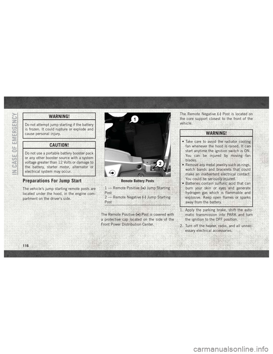
The vehicle’s jump starting remote posts are
located under the hood, in the engine com-
partment on the driver's side.The Remote Positive(+)Post is covered with
a protective cap located on the side of the
Front Power Distribution Center. The Remote Negative
(-)Post is located on
the core support closest to the front of the
vehicle.
WARNING!
• Take care to avoid the radiator cooling fan whenever the hood is raised. It can
start anytime the ignition switch is ON.
You can be injured by moving fan
blades.
• Remove any metal jewelry such as rings,
watch bands and bracelets that could
make an inadvertent electrical contact.
You could be seriously injured.
• Batteries contain sulfuric acid that can
burn your skin or eyes and generate
hydrogen gas which is flammable and
explosive. Keep open flames or sparks
away from the battery.
1. Apply the parking brake, shift the auto- matic transmission into PARK and turn
the ignition to the OFF position.
2. Turn off the heater, radio, and all unnec- essary electrical accessories.
Remote Battery Posts
1 — Remote Positive (+)Jump Starting
Post
2 — Remote Negative (-)Jump Starting
Post
IN CASE OF EMERGENCY
116
Page 119 of 204
3. If using another vehicle to jump start thebattery, park the vehicle within the jumper
cables reach, apply the parking brake and
make sure the ignition is OFF.
WARNING!
Do not allow vehicles to touch each other
as this could establish a ground connec-
tion and personal injury could result.
Jump Starting Procedure
WARNING!
Failure to follow this jump starting proce-
dure could result in personal injury or
property damage due to battery explosion.
CAUTION!
Failure to follow these procedures could
result in damage to the charging system of
the booster vehicle or the discharged ve-
hicle.
Connecting The Jumper Cables
1. Connect the positive (+)end of the jumper
cable to the remote positive (+)post of the
discharged vehicle.
NOTE:
The remote positive (+)post is located in
the engine compartment on the driver's
side under the cover of the Front Power
Distribution Center.
2. Connect the opposite end of the positive (+) jumper cable to the positive (+)post of
the booster battery.
3. Connect the negative end (-)of the jumper
cable to the negative (-)post of the
booster battery.
4. Connect the opposite end of the negative (-)jumper cable to the remote negative (-)
post of the discharged vehicle.
NOTE:
The remote negative (-)post is located in
the front of the engine compartment on
the driver's side.WARNING!
Do not connect the jumper cable to the
negative (-) post of the discharged battery.
The resulting electrical spark could cause
the battery to explode and could result in
personal injury. Only use the specific
ground point, do not use any other exposed
metal parts.
5. Start the engine in the vehicle that has the booster battery. Let the engine idle a few
minutes and then start the engine in the
vehicle with the discharged battery.
6. Once the engine is started, disconnect the jumper cables in the reverse sequence:
Disconnecting The Jumper Cables
1. Disconnect the negative end (-)of the
jumper cable from the remote negative (-)
post of the vehicle with the discharged
battery.
2. Disconnect the opposite end of the nega- tive (-)jumper cable from the negative (-)
post of the booster battery.
117
Page 120 of 204
3. Disconnect the positive end(+)of the
jumper cable from the positive (+)post of
the booster battery.
4. Disconnect the opposite end of the posi- tive (+)jumper cable from the remote
positive (+)post of the discharged
vehicle.
5. Close the cover of the Front Power Distri- bution Center.
If frequent jump starting is required to start
your vehicle you should have the battery and
charging system inspected at your authorized
dealer.
CAUTION!
Accessories plugged into the vehicle
power outlets draw power from the vehi-
cle’s battery, even when not in use (i.e.,
cellular devices, etc.). Eventually, if
plugged in long enough without engine
operation, the vehicle’s battery will dis-
charge sufficiently to degrade battery life
and/or prevent the engine from starting.
Battery Location
There are two remote jump starting posts
under the hood which is the recommended
jump start location. If access to the battery is
needed, an access panel on the driver’s side
floor will allow for battery access.
IF YOUR ENGINE OVERHEATS
In any of the following situations, you can
reduce the potential for overheating by taking
the appropriate action.
• On the highways — slow down.
• In city traffic — while stopped, place the transmission in NEUTRAL, but do not in-
crease the engine idle speed while prevent-
ing vehicle motion with the brakes.
NOTE:
There are steps that you can take to slow
down an impending overheat condition:
• If your air conditioner (A/C) is on, turn it off. The A/C system adds heat to the engine
cooling system and turning the A/C off can
help remove this heat. • You can also turn the temperature control
to maximum heat, the mode control to floor
and the blower control to high. This allows
the heater core to act as a supplement to
the radiator and aids in removing heat from
the engine cooling system.
WARNING!
You or others can be badly burned by hot
engine coolant (antifreeze) or steam from
your radiator. If you see or hear steam
coming from under the hood, do not open
the hood until the radiator has had time to
cool. Never try to open a cooling system
pressure cap when the radiator or coolant
bottle is hot.
IN CASE OF EMERGENCY
118
Page 135 of 204

3.0L Diesel Engine
1 — Power Steering Reservoir5 — Brake Fluid Reservoir
2 — Washer Solvent Reservoir 6 — Front Power Distribution Center (Fuses)
3 — Engine Oil Fill 7 — Jump Starting Location
4 — Engine Oil Dipstick 8 — Coolant Reservoir
133
Page 192 of 204
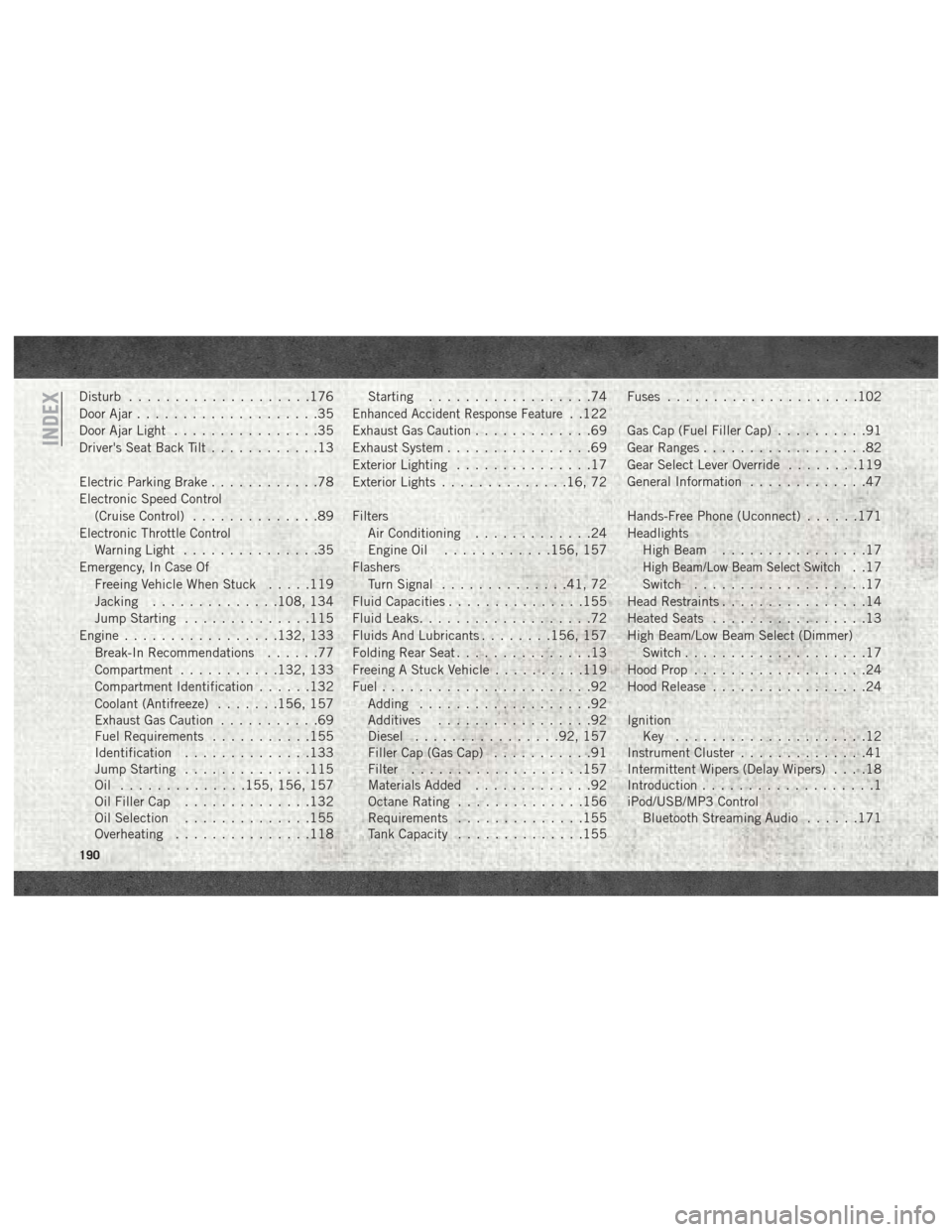
Disturb....................176
Door Ajar ....................35
Door Ajar Light ................35
Driver's Seat Back Tilt ............13
Electric Parking Brake ............78
Electronic Speed Control (Cruise Control) ..............89
Electronic Throttle Control Warning Light ...............35
Emergency, In Case Of Freeing Vehicle When Stuck .....119
Jacking ..............108, 134
Jump Starting ..............115
Engine .................132, 133
Break-In Recommendations ......77
Compartment ...........132, 133
Compartment Identification ......132
Coolant (Antifreeze) .......156, 157
Exhaust Gas Caution ...........69
Fuel Requirements ...........155
Identification ..............133
Jump Starting ..............115
Oil ..............155, 156, 157
Oil Filler Cap ..............132
Oil Selection ..............155
Overheating ...............118 Starting
..................74
Enhanced Accident Response Feature. .122
Exhaust Gas Caution .............69
Exhaust System ................69
Exterior Lighting ...............17
Exterior Lights ..............16, 72
Filters Air Conditioning .............24
Engine Oil ............156, 157
Flashers Turn Signal ..............41, 72
Fluid Capacities ...............155
Fluid Leaks ...................72
Fluids And Lubricants ........156, 157
Folding Rear Seat ...............13
Freeing A Stuck Vehicle ..........119
Fuel .......................92
Adding ...................92
Additives .................92
Diesel ................92, 157
Filler Cap (Gas Cap) ...........91
Filter ...................157
Materials Added .............92
Octane Rating ..............156
Requirements ..............155
Tank Capacity ..............155 Fuses
.....................102
Gas Cap (Fuel Filler Cap) ..........91
Gear Ranges ..................82
Gear Select Lever Override ........119
General Information .............47
Hands-Free Phone (Uconnect) ......171
Headlights High Beam ................17
High Beam/Low Beam Select Switch. .17
Switch ...................17
Head Restraints ................14
Heated Seats .................13
High Beam/Low Beam Select (Dimmer) Switch ....................17
Hood Prop ...................24
Hood Release .................24
Ignition Key .....................12
Instrument Cluster ..............41
Intermittent Wipers (Delay Wipers) ....18
Introduction ...................1
iPod/USB/MP3 Control Bluetooth Streaming Audio ......171
INDEX
190
Page 193 of 204
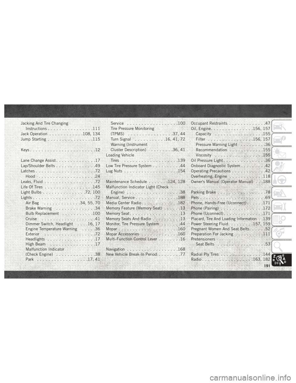
Jacking And Tire ChangingInstructions ................111
Jack Operation ............108, 134
Jump Starting ................115
Keys .......................12
Lane Change Assist ..............17
Lap/Shoulder Belts ..............49
Latches .....................72
Hood ....................24
Leaks, Fluid ..................72
Life Of Tires .................145
Light Bulbs ...............72, 100
Lights ......................72
AirBag .............34, 55, 70
Brake Warning ..............34
Bulb Replacement ...........100
Cruise ...................41
Dimmer Switch, Headlight . . . .16, 17
Engine Temperature Warning .....36
Exterior ..................72
Headlights .................17
High Beam ................17
Malfunction Indicator
(Check Engine) ..............38
Park ..................17, 41 Service
..................100
Tire Pressure Monitoring
(TPMS) ................37, 44
Turn Signal ...........16, 41, 72
Warning (Instrument
Cluster Description) ........36, 41
Loading Vehicle Tires ...................139
Low Tire Pressure System ..........44
Lug Nuts ...................154
Maintenance Schedule .......124, 128
Malfunction Indicator Light (Check Engine) ...................38
Manual, Service ...............188
Media Center Radio .............182
Memory Feature (Memory Seat) ......13
Memory Seat ..................13
Memory Seats And Radio ..........13
Monitor, Tire Pressure System .......44
Mopar .....................160
Mopar Accessories .............160
Multi-Function Control Lever ........
16
Navigation ..................168
New Vehicle Break-In Period ........77Occupant Restraints
.............47
Oil, Engine ...............156, 157
Capacity .................155
Filter ................156, 157
Pressure Warning Light .........36
Recommendation ............155
Viscosity .................155
Oil Pressure Light ...............36
Onboard Diagnostic System .........42
Operating Precautions ............42
Overheating, Engine ............118
Owner's Manual (Operator Manual) . . .188
Parking Brake .................78
Pets .......................69
Phone, Hands-Free (Uconnect) ......171
Phone (Pairing) ...............172
Phone (Uconnect) ..............171
Placard, Tire And Loading Information. .139
Power Steering Fluid .........157, 159
Pregnant Women And Seat Belts ......52
Preparation For Jacking ..........111
Pretensioners Seat Belts .................53
Radial Ply Tires ...............144
Radio ..................163, 182
191