steering Ram ProMaster City 2018 Owner's Manual
[x] Cancel search | Manufacturer: RAM, Model Year: 2018, Model line: ProMaster City, Model: Ram ProMaster City 2018Pages: 180, PDF Size: 7.52 MB
Page 56 of 180
NOTE:
If the speedometer, tachometer, or any en-
gine related gauges are not working, the Oc-
cupant Restraint Controller (ORC) may also
be disabled. In this condition the air bags
may not be ready to inflate for your protec-
tion. Have an authorized dealer service the
air bag system immediately.
WARNING!
Ignoring the Air Bag Warning Light in your
instrument panel could mean you won’t
have the air bag system to protect you in a
collision. If the light does not come on as a
bulb check when the ignition is first
turned on, stays on after you start the
vehicle, or if it comes on as you drive, have
an authorized dealer service the air bag
system immediately.
Front Air Bags
This vehicle has front air bags and lap/
shoulder belts for both the driver and front
passenger. The front air bags are a supple-
ment to the seat belt restraint systems. The
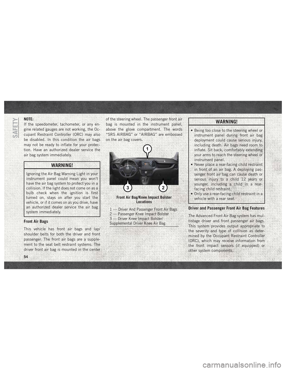
driver front air bag is mounted in the centerof the steering wheel. The passenger front air
bag is mounted in the instrument panel,
above the glove compartment. The words
“SRS AIRBAG” or “AIRBAG” are embossed
on the air bag covers.
WARNING!
• Being too close to the steering wheel or
instrument panel during front air bag
deployment could cause serious injury,
including death. Air bags need room to
inflate. Sit back, comfortably extending
your arms to reach the steering wheel or
instrument panel.
• Never place a rear-facing child restraint
in front of an air bag. A deploying pas-
senger front air bag can cause death or
serious injury to a child 12 years or
younger, including a child in a rear-
facing child restraint.
• Only use a rear-facing child restraint in a
vehicle with a rear seat.
Driver and Passenger Front Air Bag Features
The Advanced Front Air Bag system has mul-
tistage driver and front passenger air bags.
This system provides output appropriate to
the severity and type of collision as deter-
mined by the Occupant Restraint Controller
(ORC), which may receive information from
the front impact sensors (if equipped) or
other system components.
Front Air Bag/Knee Impact Bolster Locations
1—Driver And Passenger Front Air Bags
2 — Passenger Knee Impact Bolster
3 — Driver Knee Impact Bolster/
Supplemental Driver Knee Air Bag
SAFETY
54
Page 57 of 180
The first stage inflator is triggered immedi-
ately during an impact that requires air bag
deployment. A low energy output is used in
less severe collisions. A higher energy output
is used for more severe collisions.
This vehicle may be equipped with a driver
and/or front passenger seat belt buckle
switch that detects whether the driver or front
passenger seat belt is buckled. The seat belt
buckle switch may adjust the inflation rate of
the Advanced Front Air Bags.
WARNING!
• No objects should be placed over or nearthe air bag on the instrument panel or
steering wheel because any such objects
could cause harm if the vehicle is in a
collision severe enough to cause the air
bag to inflate.
• Do not put anything on or around the air
bag covers or attempt to open them
manually. You may damage the air bags
and you could be injured because the air
bags may no longer be functional. The
protective covers for the air bag cushions
WARNING!
are designed to open only when the air
bags are inflating.
• Relying on the air bags alone could lead
to more severe injuries in a collision. The
air bags work with your seat belt to
restrain you properly. In some collisions,
air bags won’t deploy at all. Always wear
your seat belts even though you have air
bags.
Front Air Bag Operation
Front Air Bags are designed to provide addi-
tional protection by supplementing the seat
belts. Front air bags are not expected to
reduce the risk of injury in rear, side, or
rollover collisions. The front air bags will not
deploy in all frontal collisions, including
some that may produce substantial vehicle
damage — for example, some pole collisions,
truck underrides, and angle offset collisions.
On the other hand, depending on the type
and location of impact, front air bags may
deploy in crashes with little vehicle front-end
damage but that produce a severe initial
deceleration. Because air bag sensors measure vehicle de-
celeration over time, vehicle speed and dam-
age by themselves are not good indicators of
whether or not an air bag should have de-
ployed.
Seat belts are necessary for your protection in
all collisions, and also are needed to help
keep you in position, away from an inflating
air bag.
When the ORC detects a collision requiring
the front air bags, it signals the inflator units.
A large quantity of non-toxic gas is generated
to inflate the front air bags.
The steering wheel hub trim cover and the
upper right side of the instrument panel
separate and fold out of the way as the air
bags inflate to their full size. The front air
bags fully inflate in less time than it takes to
blink your eyes. The front air bags then
quickly deflate while helping to restrain the
driver and front passenger.
55
Page 58 of 180
Knee Impact Bolsters
The Knee Impact Bolsters help protect the
knees of the driver and front passenger, and
position the front occupants for improved
interaction with the front air bags.
WARNING!
• Do not drill, cut, or tamper with the kneeimpact bolsters in any way.
• Do not mount any accessories to the
knee impact bolsters such as alarm
lights, stereos, citizen band radios, etc.
Supplemental Driver Knee Air Bag
This vehicle is equipped with a Supplemental
Driver Knee Air Bag mounted in the instru-
ment panel below the steering column. The
Supplemental Driver Knee Air Bag provides
enhanced protection during a frontal impact
by working together with the seat belts, pre-
tensioners, and front air bags.
Supplemental Side Air Bags
Supplemental Seat-Mounted Side Air Bags
(SABs)
This vehicle is equipped with Supplemental
Seat-Mounted Side Air Bags (SABs).
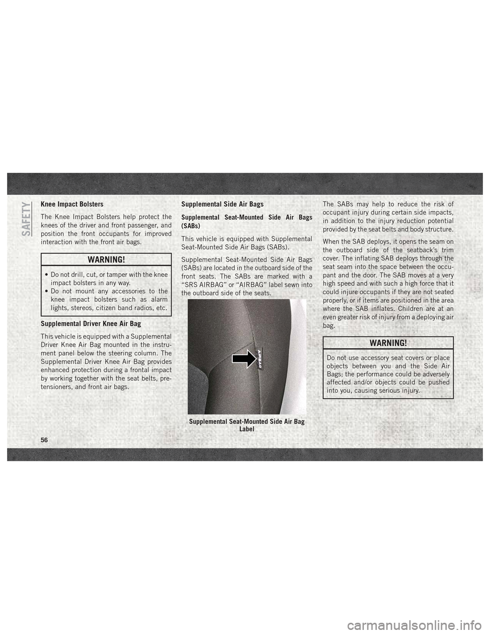
Supplemental Seat-Mounted Side Air Bags
(SABs) are located in the outboard side of the
front seats. The SABs are marked with a
“SRS AIRBAG” or “AIRBAG” label sewn into
the outboard side of the seats. The SABs may help to reduce the risk of
occupant injury during certain side impacts,
in addition to the injury reduction potential
provided by the seat belts and body structure.
When the SAB deploys, it opens the seam on
the outboard side of the seatback’s trim
cover. The inflating SAB deploys through the
seat seam into the space between the occu-
pant and the door. The SAB moves at a very
high speed and with such a high force that it
could injure occupants if they are not seated
properly, or if items are positioned in the area
where the SAB inflates. Children are at an
even greater risk of injury from a deploying air
bag.
WARNING!
Do not use accessory seat covers or place
objects between you and the Side Air
Bags; the performance could be adversely
affected and/or objects could be pushed
into you, causing serious injury.
Supplemental Seat-Mounted Side Air Bag
Label
SAFETY
56
Page 61 of 180
rollover or near rollover event, and deploy-
ment of the Side Air Bags is appropriate, the
rollover sensing system will also deploy the
seat belt pretensioners on both sides of the
vehicle.
The SABICs may help reduce the risk of
partial or complete ejection of vehicle occu-
pants through side windows in certain roll-
over or side impact events.
Air Bag System Components
NOTE:
The Occupant Restraint Controller (ORC)
monitors the internal circuits and intercon-
necting wiring associated with electrical Air
Bag System Components listed below:
• Occupant Restraint Controller (ORC)
• Air Bag Warning Light
• Steering Wheel and Column
• Instrument Panel
• Knee Impact Bolsters
• Driver and Front Passenger Air Bags
• Seat Belt Buckle Switch
• Supplemental Side Air Bags• Supplemental Knee Air Bags
• Front and Side Impact Sensors
• Seat Belt Pretensioners
If A Deployment Occurs
The front air bags are designed to deflate
immediately after deployment.
NOTE:
Front and/or side air bags will not deploy in all
collisions. This does not mean something is
wrong with the air bag system.
If you do have a collision which deploys the
air bags, any or all of the following may occur:
• The air bag material may sometimes cause
abrasions and/or skin reddening to the oc-
cupants as the air bags deploy and unfold.
The abrasions are similar to friction rope
burns or those you might get sliding along a
carpet or gymnasium floor. They are not
caused by contact with chemicals. They are
not permanent and normally heal quickly.
However, if you haven’t healed significantly
within a few days, or if you have any blis-
tering, see your doctor immediately. • As the air bags deflate, you may see some
smoke-like particles. The particles are a
normal by-product of the process that gen-
erates the non-toxic gas used for air bag
inflation. These airborne particles may irri-
tate the skin, eyes, nose, or throat. If you
have skin or eye irritation, rinse the area
with cool water. For nose or throat irritation,
move to fresh air. If the irritation continues,
see your doctor. If these particles settle on
your clothing, follow the garment manufac-
turer’s instructions for cleaning.
Do not drive your vehicle after the air bags
have deployed. If you are involved in another
collision, the air bags will not be in place to
protect you.
WARNING!
Deployed air bags and seat belt preten-
sioners cannot protect you in another col-
lision. Have the air bags, seat belt preten-
sioners, and the seat belt retractor
assemblies replaced by an authorized
dealer immediately. Also, have the Occu-
pant Restraint Controller System serviced
as well.
59
Page 62 of 180
NOTE:
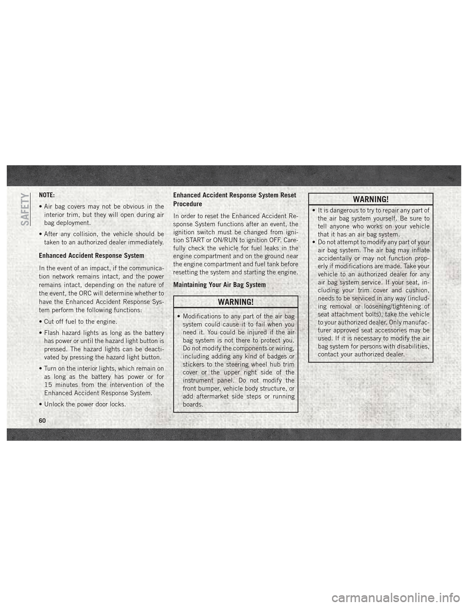
• Air bag covers may not be obvious in theinterior trim, but they will open during air
bag deployment.
• After any collision, the vehicle should be taken to an authorized dealer immediately.
Enhanced Accident Response System
In the event of an impact, if the communica-
tion network remains intact, and the power
remains intact, depending on the nature of
the event, the ORC will determine whether to
have the Enhanced Accident Response Sys-
tem perform the following functions:
• Cut off fuel to the engine.
• Flash hazard lights as long as the batteryhas power or until the hazard light button is
pressed. The hazard lights can be deacti-
vated by pressing the hazard light button.
• Turn on the interior lights, which remain on as long as the battery has power or for
15 minutes from the intervention of the
Enhanced Accident Response System.
• Unlock the power door locks.
Enhanced Accident Response System Reset
Procedure
In order to reset the Enhanced Accident Re-
sponse System functions after an event, the
ignition switch must be changed from igni-
tion START or ON/RUN to ignition OFF. Care-
fully check the vehicle for fuel leaks in the
engine compartment and on the ground near
the engine compartment and fuel tank before
resetting the system and starting the engine.
Maintaining Your Air Bag System
WARNING!
• Modifications to any part of the air bag system could cause it to fail when you
need it. You could be injured if the air
bag system is not there to protect you.
Do not modify the components or wiring,
including adding any kind of badges or
stickers to the steering wheel hub trim
cover or the upper right side of the
instrument panel. Do not modify the
front bumper, vehicle body structure, or
add aftermarket side steps or running
boards.
WARNING!
• It is dangerous to try to repair any part ofthe air bag system yourself. Be sure to
tell anyone who works on your vehicle
that it has an air bag system.
• Do not attempt to modify any part of your
air bag system. The air bag may inflate
accidentally or may not function prop-
erly if modifications are made. Take your
vehicle to an authorized dealer for any
air bag system service. If your seat, in-
cluding your trim cover and cushion,
needs to be serviced in any way (includ-
ing removal or loosening/tightening of
seat attachment bolts), take the vehicle
to your authorized dealer. Only manufac-
turer approved seat accessories may be
used. If it is necessary to modify the air
bag system for persons with disabilities,
contact your authorized dealer.
SAFETY
60
Page 82 of 180
ENGINE BREAK-IN
RECOMMENDATIONS — GASOLINE
ENGINE
A long break-in period is not required for the
engine and drivetrain (transmission and axle)
in your vehicle.
Drive moderately during the first 300 miles
(500 km). After the initial 60 miles
(100 km), speeds up to 50 or 55 mph (80 or
90 km/h) are desirable.
While cruising, brief full-throttle acceleration
within the limits of local traffic laws contrib-
utes to a good break-in. Wide-open throttle
acceleration in low gear can be detrimental
and should be avoided.
The engine oil installed in the engine at the
factory is a high-quality energy conserving
type lubricant. Oil changes should be consis-
tent with anticipated climate conditions un-
der which vehicle operations will occur. For
the recommended viscosity and quality
grades, refer to “Fluids And Lubricants” in
“Technical Specifications”.
CAUTION!
Never use Non-Detergent Oil or Straight
Mineral Oil in the engine or damage may
result.
NOTE:
A new engine may consume some oil during
its first few thousand miles (kilometers) of
operation. This should be considered a nor-
mal part of the break-in and not interpreted
as a problem. Please check your oil level with
the engine oil indicator often during the
break in period. Add oil as required.
SPEED CONTROL
When engaged, the Speed Control takes over
accelerator operations at speeds greater than
25 mph (40 km/h).
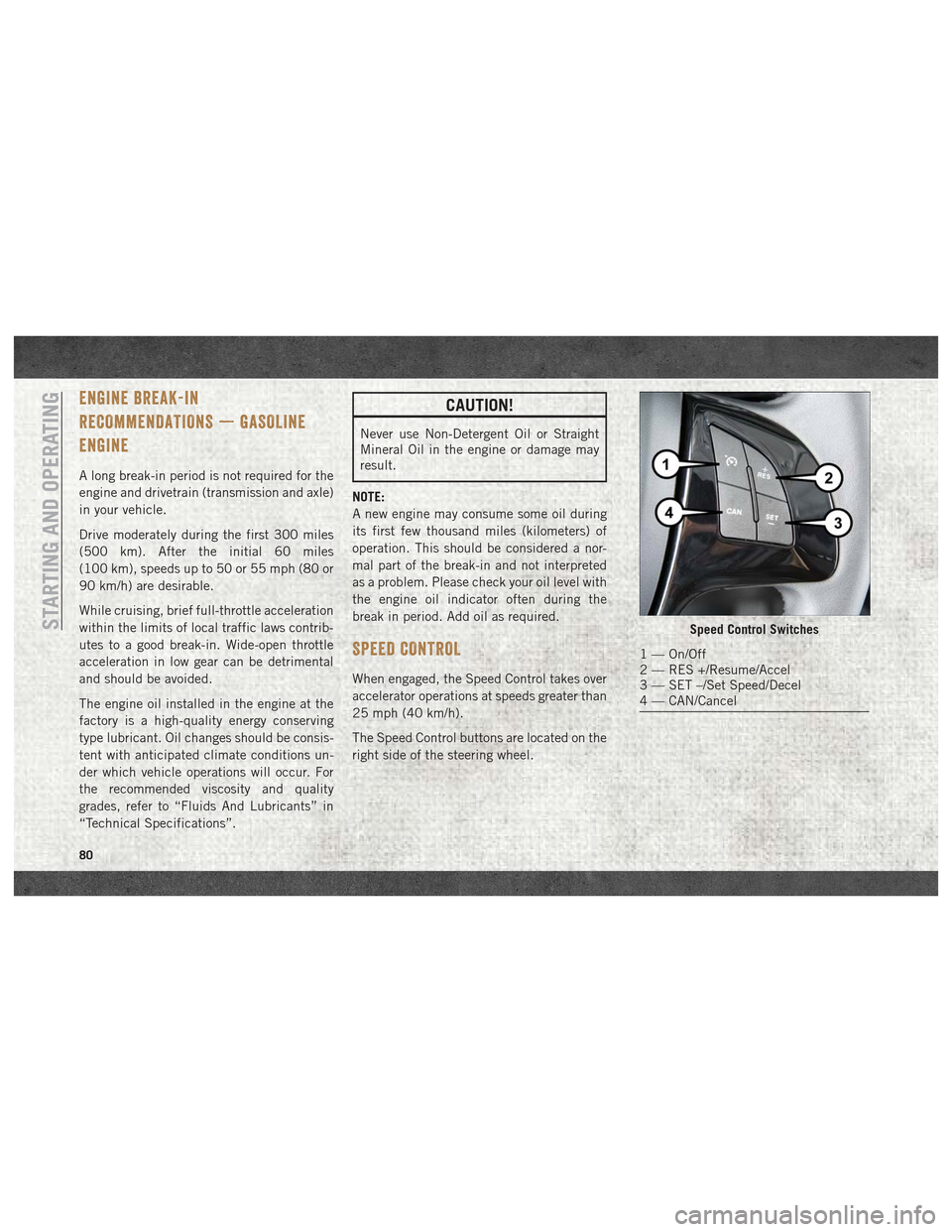
The Speed Control buttons are located on the
right side of the steering wheel.
Speed Control Switches
1 — On/Off
2 — RES +/Resume/Accel
3 — SET –/Set Speed/Decel
4 — CAN/Cancel
STARTING AND OPERATING
80
Page 91 of 180

FUSES
WARNING!
• When replacing a blown fuse, always usean appropriate replacement fuse with
the same amp rating as the original fuse.
Never replace a fuse with another fuse of
higher amp rating. Never replace a
blown fuse with metal wires or any other
material. Do not place a fuse inside a
circuit breaker cavity or vice versa. Fail-
ure to use proper fuses may result in
WARNING!
serious personal injury, fire and/or prop-
erty damage.
• Before replacing a fuse, make sure that
the ignition is off and that all the other
services are switched off and/or disen-
gaged.
• If the replaced fuse blows again, contact
an authorized dealer.
• If a general protection fuse for safety
systems (air bag system, braking sys-
tem), power unit systems (engine sys-
tem, transmission system) or steering
WARNING!
system blows, contact an authorized
dealer.
Underhood Fuses
The Front Distribution Unit is located on the
right side of the engine compartment, next to
the battery. To access the fuses, remove fas-
teners and remove the cover.
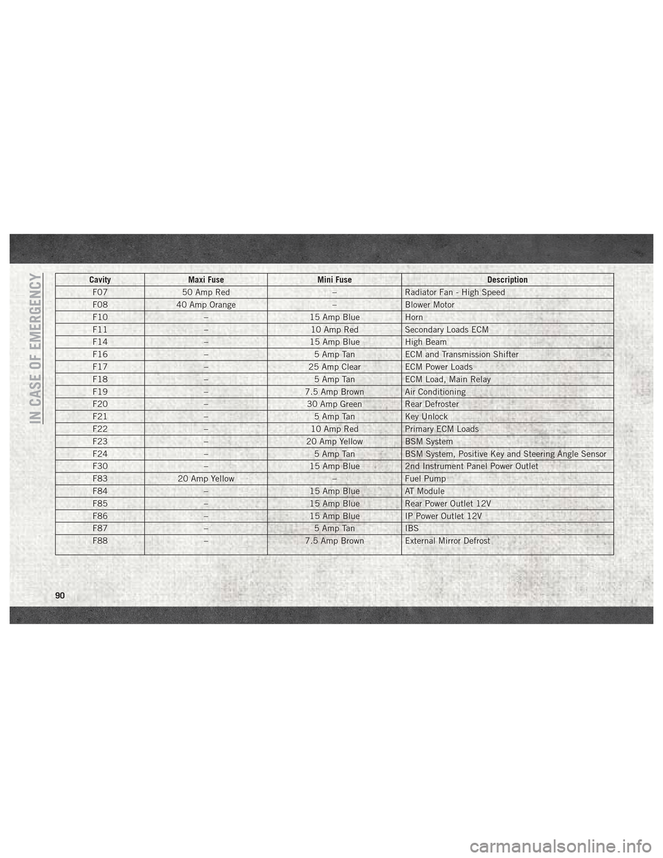
The ID number of the electrical component
corresponding to each fuse can be found on
the back of the cover.
Cavity Maxi Fuse Mini Fuse Description
F01 60 Amp Blue –Body Controller
F02 40 Amp Orange –Rear Power Windows, Fog Lamps, Front Heated Seats
(If Equipped)
F02 30 Amp Green –Rear Power Windows, Front Heated Seats (If
Equipped)
F02 30 Amp Green –Fog Lamps, Front Heated Seats (If Equipped)
F02 20 Amp Yellow –Front Heated Seats
F03 20 Amp Yellow –Ignition Switch
F04 40 Amp Orange –BSM System Module
F06 20 Amp Yellow –Radiator Fan - Low Speed
89
Page 92 of 180
CavityMaxi Fuse Mini Fuse Description
F07 50 Amp Red –Radiator Fan - High Speed
F08 40 Amp Orange –Blower Motor
F10 –15 Amp BlueHorn
F11 –10 Amp RedSecondary Loads ECM
F14 –15 Amp BlueHigh Beam
F16 –5 Amp TanECM and Transmission Shifter
F17 –25 Amp ClearECM Power Loads
F18 –5 Amp TanECM Load, Main Relay
F19 –7.5 Amp Brown Air Conditioning
F20 –30 Amp Green Rear Defroster
F21 –5 Amp TanKey Unlock
F22 –10 Amp RedPrimary ECM Loads
F23 –20 Amp Yellow BSM System
F24 –5 Amp TanBSM System, Positive Key and Steering Angle Sensor
F30 –15 Amp Blue2nd Instrument Panel Power Outlet
F83 20 Amp Yellow –Fuel Pump
F84 –15 Amp BlueAT Module
F85 –15 Amp BlueRear Power Outlet 12V
F86 –15 Amp BlueIP Power Outlet 12V
F87 –5 Amp TanIBS
F88 –7.5 Amp Brown External Mirror Defrost
IN CASE OF EMERGENCY
90
Page 106 of 180
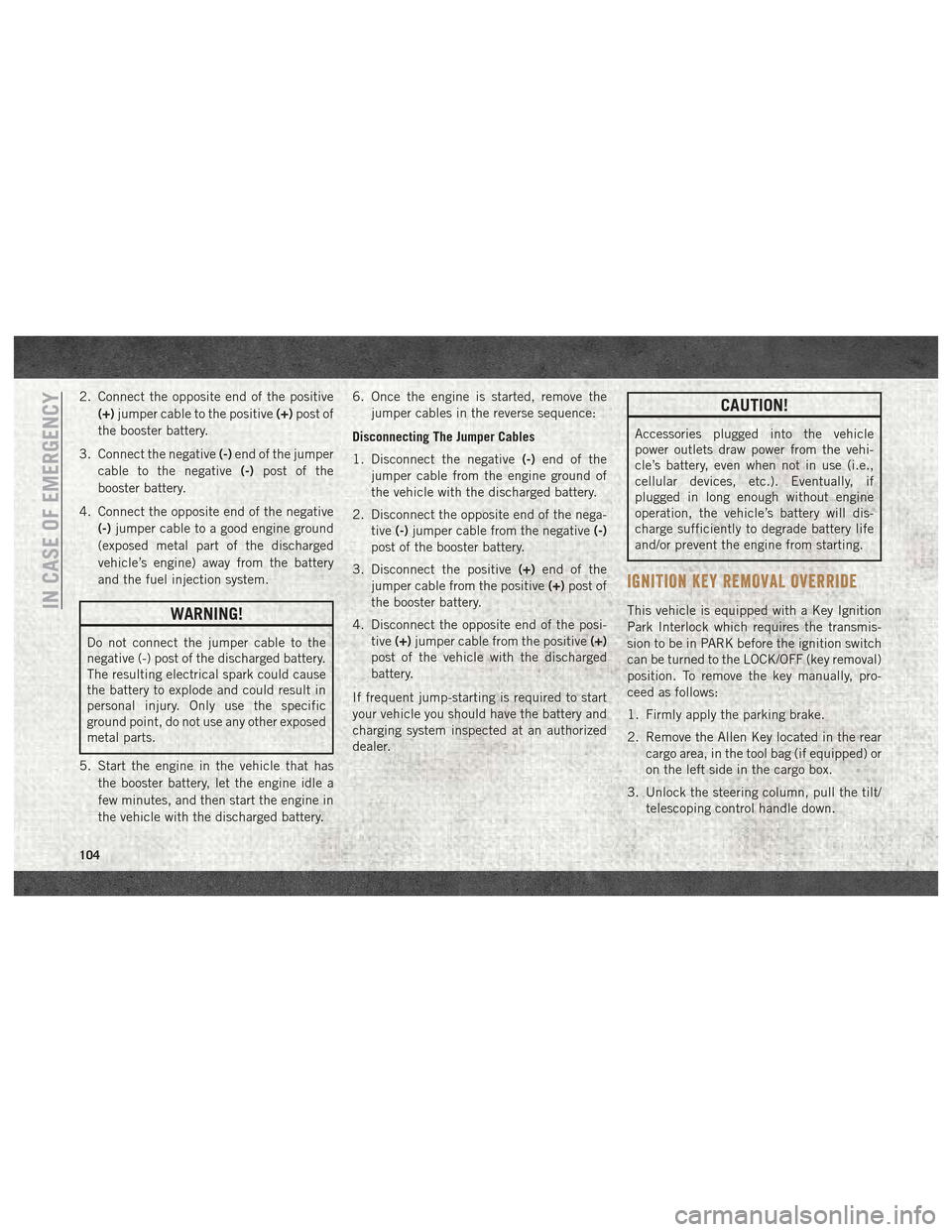
2. Connect the opposite end of the positive(+) jumper cable to the positive (+)post of
the booster battery.
3. Connect the negative (-)end of the jumper
cable to the negative (-)post of the
booster battery.
4. Connect the opposite end of the negative (-)jumper cable to a good engine ground
(exposed metal part of the discharged
vehicle’s engine) away from the battery
and the fuel injection system.
WARNING!
Do not connect the jumper cable to the
negative (-) post of the discharged battery.
The resulting electrical spark could cause
the battery to explode and could result in
personal injury. Only use the specific
ground point, do not use any other exposed
metal parts.
5. Start the engine in the vehicle that has the booster battery, let the engine idle a
few minutes, and then start the engine in
the vehicle with the discharged battery. 6. Once the engine is started, remove the
jumper cables in the reverse sequence:
Disconnecting The Jumper Cables
1. Disconnect the negative (-)end of the
jumper cable from the engine ground of
the vehicle with the discharged battery.
2. Disconnect the opposite end of the nega- tive (-)jumper cable from the negative (-)
post of the booster battery.
3. Disconnect the positive (+)end of the
jumper cable from the positive (+)post of
the booster battery.
4. Disconnect the opposite end of the posi- tive (+)jumper cable from the positive (+)
post of the vehicle with the discharged
battery.
If frequent jump-starting is required to start
your vehicle you should have the battery and
charging system inspected at an authorized
dealer.
CAUTION!
Accessories plugged into the vehicle
power outlets draw power from the vehi-
cle’s battery, even when not in use (i.e.,
cellular devices, etc.). Eventually, if
plugged in long enough without engine
operation, the vehicle’s battery will dis-
charge sufficiently to degrade battery life
and/or prevent the engine from starting.
IGNITION KEY REMOVAL OVERRIDE
This vehicle is equipped with a Key Ignition
Park Interlock which requires the transmis-
sion to be in PARK before the ignition switch
can be turned to the LOCK/OFF (key removal)
position. To remove the key manually, pro-
ceed as follows:
1. Firmly apply the parking brake.
2. Remove the Allen Key located in the rear cargo area, in the tool bag (if equipped) or
on the left side in the cargo box.
3. Unlock the steering column, pull the tilt/ telescoping control handle down.IN CASE OF EMERGENCY
104
Page 107 of 180
4. Pull the steering wheel outward until it isin the end of the travel position, then lock
the steering column in position, push the
control handle up until fully engaged.
5. Using the Allen Key, undo the lower steer- ing column cover screws, and remove the
lower cover.
6. Pull the release tab downwards using one hand and with the other one remove the
key, sliding it outwards.
7. Once the key is removed, reinstall the steering column cover.
CAUTION!
It is advisable to contact your authorized
dealer to have the reinstall procedure car-
ried out. If you would like to proceed in
performing the reinstall procedure special
attention must be paid to the correct cou-
pling of the clips. Otherwise damage to the
cover or noise might be heard due to incor-
rect fastening of the lower cover.
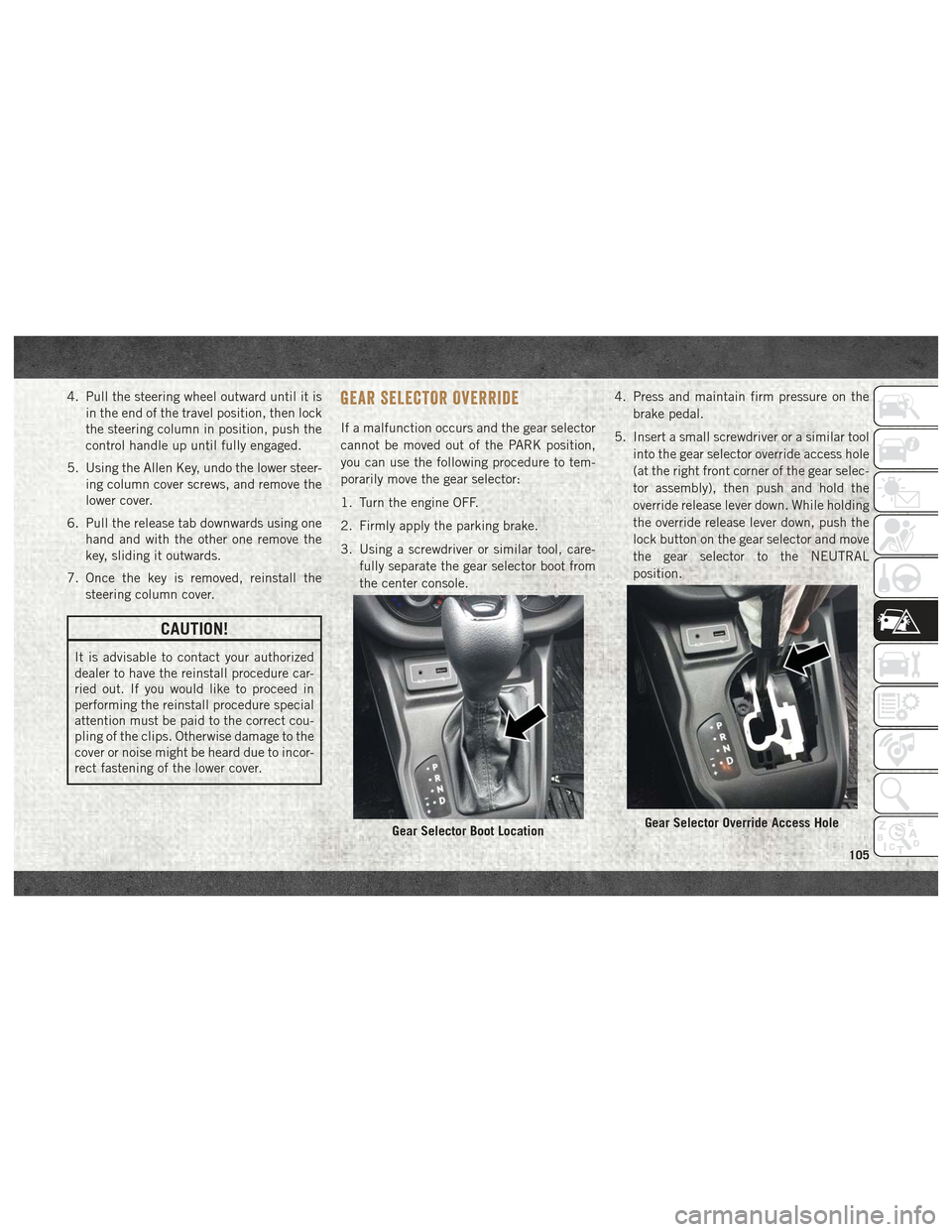
GEAR SELECTOR OVERRIDE
If a malfunction occurs and the gear selector
cannot be moved out of the PARK position,
you can use the following procedure to tem-
porarily move the gear selector:
1. Turn the engine OFF.
2. Firmly apply the parking brake.
3. Using a screwdriver or similar tool, care-
fully separate the gear selector boot from
the center console. 4. Press and maintain firm pressure on the
brake pedal.
5. Insert a small screwdriver or a similar tool into the gear selector override access hole
(at the right front corner of the gear selec-
tor assembly), then push and hold the
override release lever down. While holding
the override release lever down, push the
lock button on the gear selector and move
the gear selector to the NEUTRAL
position.
Gear Selector Boot LocationGear Selector Override Access Hole
105