RENAULT KANGOO 1997 KC / 1.G Electrical Equipment Workshop Manual
Manufacturer: RENAULT, Model Year: 1997, Model line: KANGOO, Model: RENAULT KANGOO 1997 KC / 1.GPages: 83
Page 1 of 83
Renault 1997
77 11 194 271JULY 1997Edition Anglaise
"The repair methods given by the manufacturer in this document are based on the
technical specifications current when it was prepared.
The methods may be modified as a result of changes introduced by the
manufacturer in the production of the various component units and accessories
from which his vehicles are constructed."All copyrights reserved by Renault.
Copying or translating, in part or in full, of this document or use of the service part
reference numbering system is forbidden without the prior written authority of
Renault.
C
Electrical equipment
BATTERY - HEADLIGHTS
REAR AND INTERIOR LIGHTING
INSTRUMENT PANEL
CONTROLS - SIGNALS
WIPERS
ELECTRICAL ASSISTANCE EQUIPMENT
WIRING
IMMOBILISER
FC0A - FC0C - FC0D - FC0E - KC0A - KC0C - KC0D - KC0E
Page 2 of 83

EXPLODED VIEW
PRO80.1
Page 3 of 83
81-1
81-2
Contents
BATTERIE PROJECTEURS
Battery
Special notes
Headlights
Lens units and indicators
Remote adjustment
80-1
80-3
80-4
ECLAIRAGE ARRIERE
Courtesy light
Fuses
PagePage
Electrical
Equipment
WIPERS
Front windscreen wiper
Rear screen wiper
Electric washer pump
85-1
85-3
85-4
85
Coded key immobiliser system82-1
IMMOBILISER82
Relay plate87-1
ELECTRICAL ASSISTANCE EQUIPMENT
REAR AND INTERIOR LIGHTS
BATTERY - HEADLIGHTS80
81
87
Dashboard
Instrument panel
Fuel level sensor
Oil level sensor
Coolant temperature sensor83-1
83-6
83-10
83-12
83-13
INSTRUMENT PANEL83
Windscreen wiper stalk
Lights stalk
Stalk mounting
Rotary switch under steering
wheel
Ignition switch84-1
84-2
84-3
84-4
84-6
CONTROLS - SIGNALS84
WIRING
Heated rear screen
Remote control for door locking
Airbags and seat belt pretensioners
88-1
88-3
88-8
88
Page 4 of 83

BATTERY
Special notes
To remove the battery, slacken mounting (A).
80
It is vital :
• to ensure that there is no sulphation on the
terminals,
• to clean and grease the terminals if necessary,
• to check that the nuts are correctly tightened
on the terminals. Incorrect contact could cause
starting faults or charging faults which could
cause sparks, making the battery liable to
explode,
•to check the electrolyte level.
Batteries with sets of removable plugs:
• remove the cover by hand or by using a tool
(stiff spatula),
• check that the electrolyte level in all the cells is
well above the level of the separators,
• if necessary, use demineralised water to top up
the level.
Note: certain types of battery have translucent
bodies which allow the level of the electrolyte to
be seen.
Never add electrolyte or other products to the
battery.
A - CHECKING
Check and ensure that:
• the battery tray and cover are not cracked or
split,
• the top of the battery is clean,
• the terminals are in good condition.
12422R
80-1
Page 5 of 83
BATTERY
Special notes
80
B- PRECAUTIONS
It should be remembered that a battery:
• contains sulphuric acid, which is a dangerous
product,
• produces oxygen and hydrogen during
charging. The mixture of these two gases
forms a detonating gas , hence the risk of an
explosion.
1) DANGER = ACID
The sulphuric acid solution is a highly aggressive,
toxic and corrosive product. It attacks skin,
clothing, concrete and corrodes most metals.
It is also very important, when handling a battery,
to take the following precautions:
• to protect your eyes with goggles,
• to wear anti-acid gloves and clothing.
If acid splashes on to your clothing, rinse all the
contaminated areas thoroughly in water. If your
eyes are affected, consult a doctor.
2) DANGER = RISK OF EXPLOSION
When a battery is charging (either in a vehicle or
elsewhere), oxygen and hydrogen are produced.
Gas production is at a maximum when the battery
is completely charged and the quantity of gas
produced is proportional to the intensity of the
charging current.
The oxygen and the hydrogen join together in the
open air, on the surface of the plates and form a
highly explosive mixture.
The smallest of sparks, a cigarette or a recently
extinguished match are sufficient to cause an
explosion. The explosion is so strong that the
battery can shatter and the acid is dispersed into
the surrounding atmosphere. People nearby are
at risk (shattered casing parts, acid splashes). The
acid splashes are harmful to the eyes, face and
hands. They also attack clothing.
Safeguarding against the danger of explosion,
which can be caused by a poorly handled battery,
must be taken very seriously. Avoid all risks of
sparks.
• Check that the "consumers" are switched off,
before disconnecting or reconnecting a
battery.
• When a battery is being charged in a room,
switch off the charger before connecting or
disconnecting the battery.
• Do not put any metallic items onto the battery
so as not to cause a short circuit across the
terminals.
• Never place a naked flame, a welding torch,
hot air gun, a cigarette or a lighted match near
to a battery.
80-2
Page 6 of 83
HEADLIGHTS
Lens units and indicators
80
NOTE : The lens unit and indicators cannot be se-
parated.
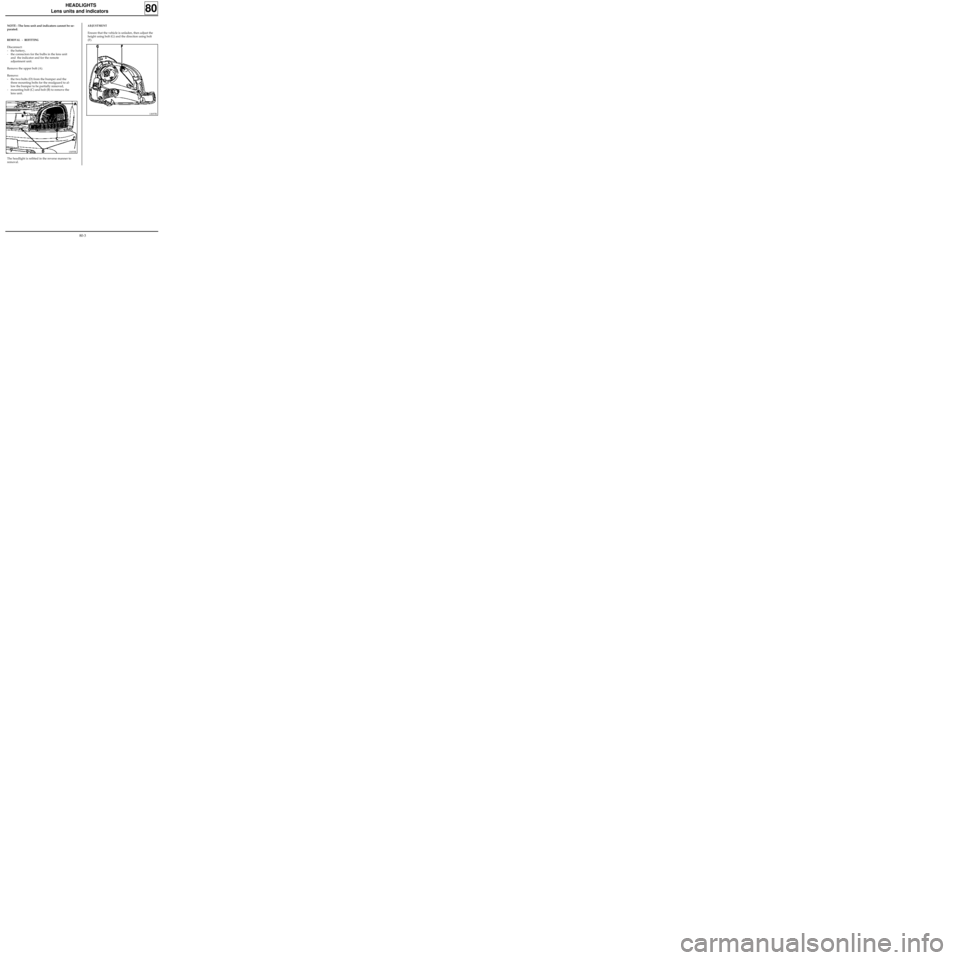
REMOVAL - REFITTING
Disconnect:
- the battery,
- the connectors for the bulbs in the lens unit
and the indicator and for the remote
adjustment unit.
Remove the upper bolt (A).
Remove:
- the two bolts (D) from the bumper and the
three mounting bolts for the mudguard to al-
low the bumper to be partially removed,
- mounting bolt (C) and bolt (B) to remove the
lens unit.
ADJUSTMENT
Ensure that the vehicle is unladen, then adjust the
height using bolt (G) and the direction using bolt
(F).
13055R
The headlight is refitted in the reverse manner to
removal.
13057R
80-3
Page 7 of 83
HEADLIGHTS
Remote adjustment
80
13056S
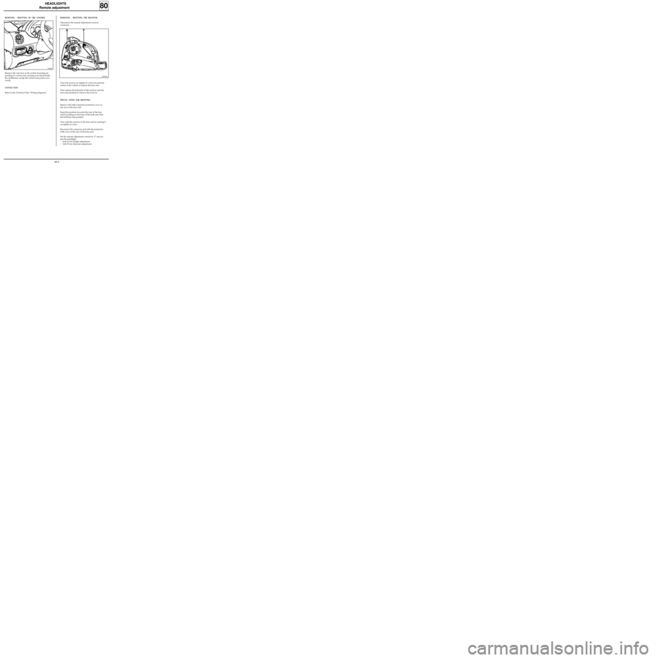
REMOVING - REFITTING OF THE CONTROL
Remove the coin tray or the switch mounting de-
pending on version and, passing your hand inside
the dashboard, unclip the control and push it out-
wards.
CONNECTION
Refer to the Technical Note "Wiring diagrams".
REMOVING - REFITTING THE RECEIVER
Disconnect the remote adjustment receiver
connector.
Turn the receiver an eighth of a turn towards the
centre of the vehicle to release the lens unit.
Then release the ball joint of the receiver and the
lens unit parabola to remove the receiver.
SPECIAL NOTES FOR REFITTING
Remove the bulb connector protective cover at
the rear of the lens unit.
Keep the parabola towards the rear of the lens
unit by pulling on the base of the bulb and click
the ball joint into position.
Now refit the receiver to the lens unit by turning it
an eighth of a turn.
Reconnect the connector and refit the protective
bulb cover at the rear of the lens unit.
Set the remote adjustment control to "0" and ad-
just the headlight:
- bolt (G) for height adjustment,
- bolt (F) for direction adjustment.
13057R1
80-4
Page 8 of 83
REAR AND INTERIOR LIGHTS
Courtesy light
81
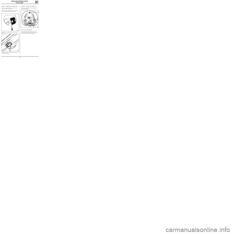
REMOVING - REFITTING THE COURTESY LIGHT
Remove the light diffuser using a screwdriver to
lever it out at the two points (A).
NOTE : The map reading light diffuser (depending
on equipment) is removed in the same way.
13073R
Remove the two courtesy light console mounting
bolts (B).
13072R
SPECIAL NOTES FOR REFITTING
When refitting the mounting (D), check that the
switch (E) is positioned to the right (see above) so
the contacts are not damaged on refitting.
Release the assembly towards the front and dis-
connect the connector.
REMOVING - REFITTING THE MOUNTING (D)
After removing the bulb, remove bolt (C) and un-
clip the mounting (D).
13074R
81-1
Page 9 of 83
REAR AND INTERIOR LIGHTS
Fuses
81
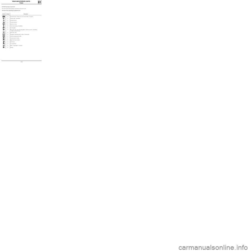
FUSE BOX (passenger compartment)
This unit is located in the passenger compartment on the driver’s side.
Allocation of fuses (depending on equipment level).
Symbol Rating Description
10
15
30
30
30
20
15
15
15
15
10
25
25
20
15
15
25Instrument panel / Electric rear view mirrors/ Radio / Car phone
Courtesy light / Immobiliser
Consumer cut-out
Towing connection
Heated rear screen
Central door locking / Immobiliser
Front fog lights
Rear screen wash - wipe/
Reversing lights / Heated rear screen / Immobiliser
/ Lights on reminder buzzer
Front wash - wipe
Stop lights/ Instrument panel/ Airbag / Pretensioners
Anti-lock braking system (ABS)
Left hand electric window
Right hand electric window
Heated seats
Air conditioning
Radio / Cigar lighter / Car phone
Heating
81-2
Page 10 of 83
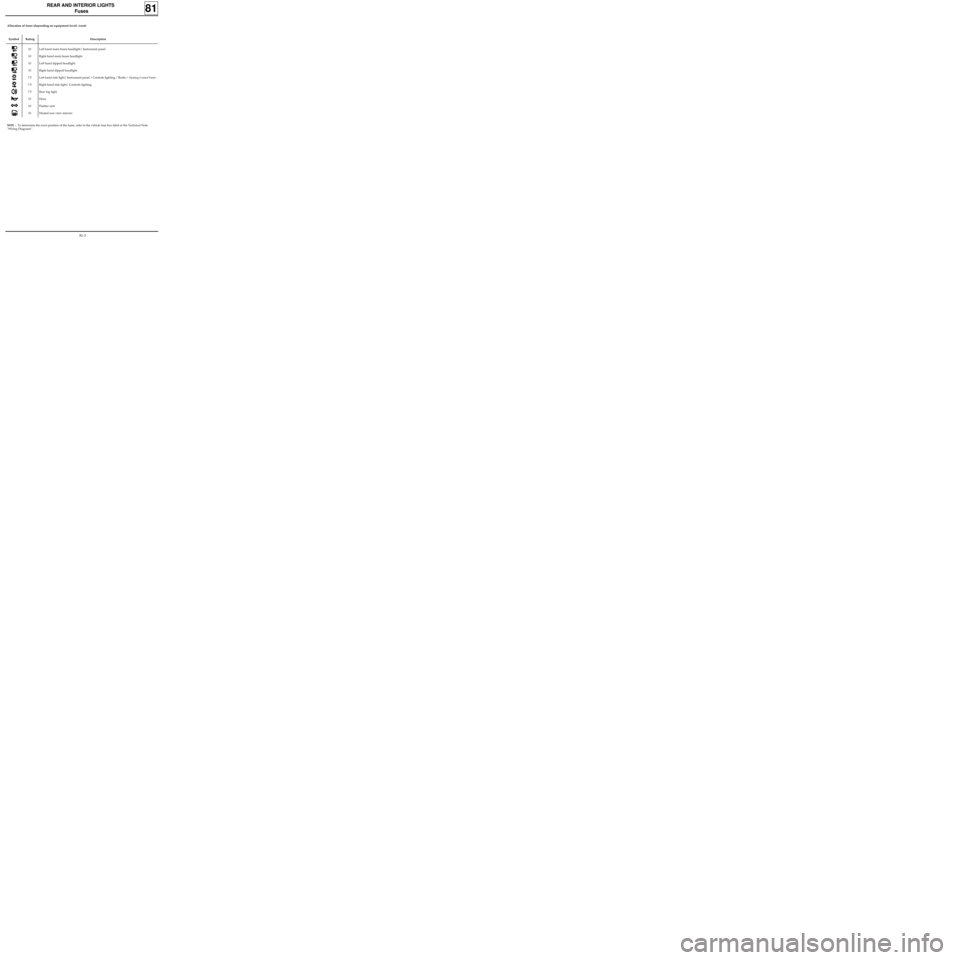
Symbol Rating Description
10
10
10
10
7.5
7.5
7.5
15
10
10Left hand main beam headlight/ Instrument panel
Right hand main beam headlight
Left hand dipped headlight
Right hand dipped headlight
Left hand side light/
Instrument panel / Controls lighting / Radio / Heating Control Panel
Right hand side light/ Controls lighting
Rear fog light
Horn
Flasher unit
Heated rear view mirrors
REAR AND INTERIOR LIGHTS
Fuses
81
NOTE : To determine the exact position of the fuses, refer to the vehicle fuse box label or the Technical Note
"Wiring Diagrams".
Allocation of fuses (depending on equipment level). (cont)
81-3