steering RENAULT KANGOO 1997 KC / 1.G Electrical Equipment User Guide
[x] Cancel search | Manufacturer: RENAULT, Model Year: 1997, Model line: KANGOO, Model: RENAULT KANGOO 1997 KC / 1.GPages: 83
Page 44 of 83
CONTROLS - SIGNALS
Rotary switch under steering wheel
This makes the electrical connection between the
steering column and the steering wheel.
It consists of a strip of conductor tracks (airbag)
whose length is designed to guarantee 2.5
steering wheel turns (steering lock plus safety
margin) on each side.
REMOVAL - REFITTING
84
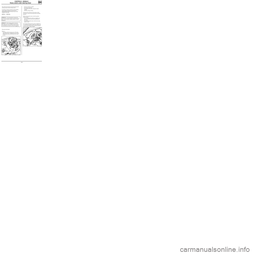
- the horn connector, if fitted,
- the steering wheel bolt,
- the steering wheel after setting the wheels
straight,
- the half cowlings (3 bolts).
Disconnect the connector for the rotary switch
and remove it after removing the three mounting
bolts (E).
Before removing the rotary switch its position
must be noted:
- by ensuring that the wheels are straight on re-
moval so that the track may be positioned in
the centre,
- by immobilising the rotary switch rotor using
adhesive tape.
If it is being replaced, the new part is supplied rea-
dy centred by an adhesive label which will tear off
as soon as the steering wheel is turned for the first
time (fit with the wheels straight).
12970R3
Disconnect the battery.
Remove:
- the airbag cushion by the two torx T30 bolts
(tightening torque : 0.5 daN.m) located behind
the steering wheel and disconnect the connec-
tor (D),
IMPORTANT: It is not permitted to operate the
pyrotechnical systems (airbags and pretensioners)
near a source of heat or flame as there is a risk of
triggering.
IMPORTANT : If the steering wheel is removed,
the airbag connector (D)
MUST be disconnected.
The airbag has a connector which short circuits if
it is disconnected to prevent incorrect triggering.
12973R
84-4
Page 45 of 83
CONTROLS - SIGNALS
Rotary switch under steering wheel
Special notes for refitting
Ensure the wheels are still straight.
Ensure the rotary switch under the steering wheel
is still immobilised before refitting.
If there is any doubt follow the method for cen-
tring described in section 88 "driver’s airbag".
Renew the steering wheel bolt each time it is re-
moved (pre-bonded bolt).
Observe the correct tightening torque (4.5
daN.m).
84
IMPORTANT
Before reconnecting the driver’s airbag cushion,
check to see if the system is operating correctly as
follows:
•check the airbag warning light on the
instrument panel is illuminated when the
ignition is on,
•connect a dummy ignition module to the
driver’s airbag connector and check that the
warning light extinguishes,
•switch the ignition off, connect the airbag
cushion in place of the dummy ignition module
and secure the cushion to the steering wheel,
•switch the ignition on. Check the warning light
illuminates for three seconds when the ignition
is switched on then extinguishes and remains
extinguished.
If the warning light does not operate exactly as
described above, refer to the fault finding section
and test the system using the XRBAG (Elé. 1288)
(see section 88).
IMPORTANT: if these instructions are not obser-
ved, the systems may not operate normally and
may be incorrectly triggered.
84-5
Page 60 of 83
WIRING
Remote control for door locking
88
Ignition off:
1.Press and hold the central door locking button
for a few seconds until the doors lock and un-
lock.
From this moment, the operator has 10 se-
conds to carry out the next operation.
NOTE: The 10 seconds are shown by the illu-
mination of the red immobiliser warning light
(if fitted) and bargraph 17 LH on the XR25
(code
D56, fiche n° 56).
2.Press the remote control twice (the doors lock
and unlock and the red warning light extin-
guishes, if fitted).
NOTE : If both remote controls (if fitted) are
desynchronised, two resynchronisation proce-
dures will have to be carried out (one for each
remote control).
IMPORTANT: To ensure that the infrared code
is correctly transmitted it is essential to direct
the transmitter correctly towards the receiver.
If the procedure fails it will be necessary to
restart from the beginning (infrared remote
control only).
3.The procedure is complete - check that the
doors lock correctly.
Removal - Refitting
The dashboard must be partially removed to re-
move the decoder unit.
Remove:
- the steering wheel with the wheels straight,
- the half cowlings under the steering wheel,
- the knee protector under the steering column,
- the lights and wiper controls,
- the instrument panel surround,
- the instrument panel,
- the ashtray, its mounting and the two dash-
board mounting bolts on the heating unit,
- the trim at the bottom of the dashboard on the
driver’s side,
- the two speaker grilles on the dashboard,
- the dashboard mountings.
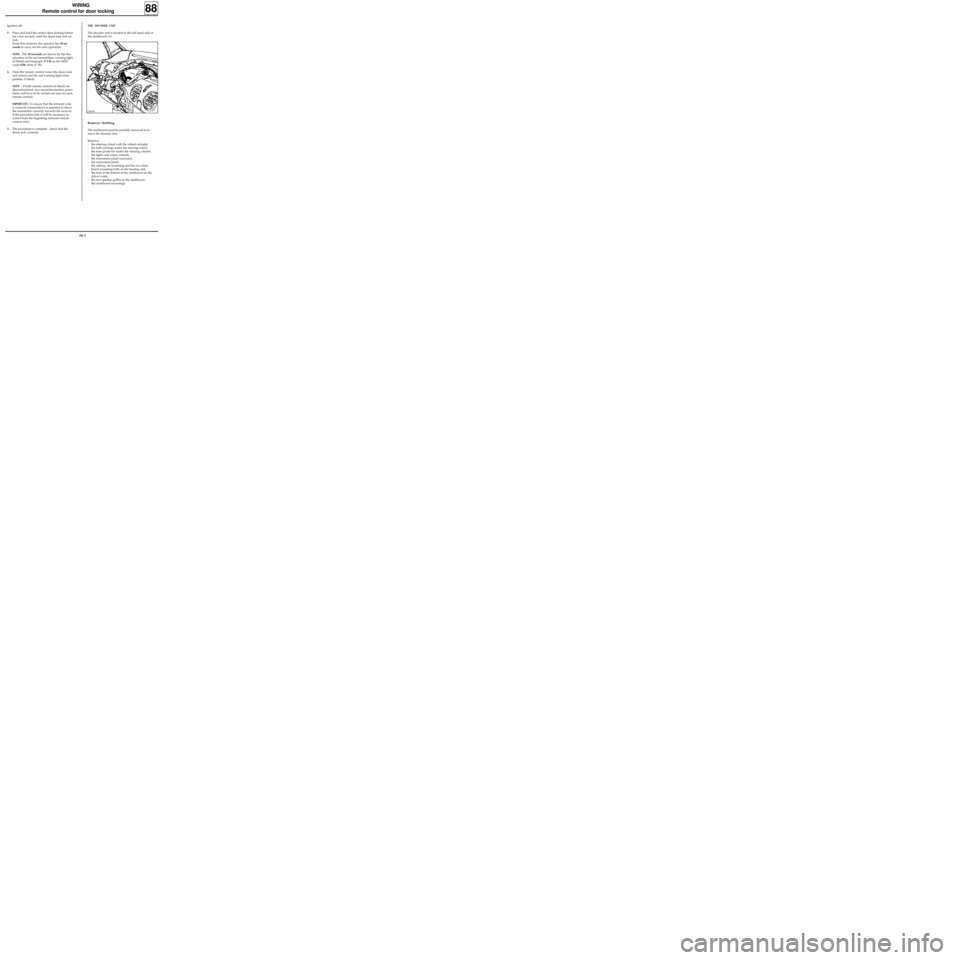
THE DECODER UNIT
The decoder unit is located in the left hand side of
the dashboard (A).
12967R
88-5
Page 63 of 83
96310-1S
MAB11197S
WIRING
Airbags and seat belt pretensioners
GENERAL
88
IMPORTANT : all work on the airbag and
pretensioner systems must be carried out by
qualified personnel who have received the proper
training.
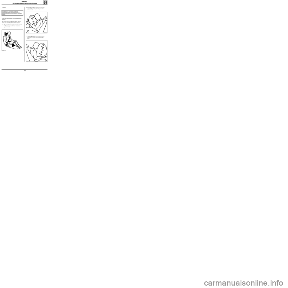
There are 3 safety systems which supplement the
seat belt.
If a frontal impact is sufficiently strong, the elec-
tronic unit controlling these systems triggers:
•The pretensioners which restrict the seat belts
for the front seats so that they are pressed
against the body.
•The airbag cushion which inflates from the
centre of the steering wheel to protect the
driver’s head.
•The airbag module which inflates from the
dashboard to protect the front passenger’s
head.
98124S
88-8
Page 64 of 83

DI8816 DI8817
WIRING
Airbags and seat belt pretensioners
88
FUNCTION AND OPERATION OF THE AIRBAGS AND PRETENSIONERS
1) Function
In the event of an accident, the airbag prevents the head striking the steering wheel or dashboard.
It also reduces the maximum acceleration of the head, by absorption.
2) Trigger threshold
Generally speaking, there are four different basic situations.
1) FRONTAL IMPACT AGAINST A OBSTACLE
The trigger speed depends on the obstacle’s
surface. The softer the surface, the higher the
speed.
The pretensioner generally triggers at a lower
speed than the airbag.
2) OFFSET IMPACT AGAINST A OBSTACLE
In this case, the airbag trigger speed depends on
the angle of impact α.
The greater the angle, the higher the vehicle
speed for triggering.
ADirection of travel
BCentre of gravity
88-9
Page 66 of 83
WIRING
Airbags and seat belt pretensioners
88
92656S
The new 30-track computers are provided with
the K and L lines for fault finding with the XR25
(except for vehicles with pretensioners only).
This enables computer faults or faulty lines to be
detected in the system (see section on fault fin-
ding).
NOTE: before each operation an auxiliary func-
tion enables the ignition lines to be de-activated
to prevent the risk of triggering the pyrotechnic
gas generators.
Various vehicle configurations are possible:
Vehicle fitted with:
- pretensioners only,
- pretensioners and driver’s airbag,
- pretensioners and driver’s airbag and passen-
ger’s airbag.
NOTE :
• A vehicle fitted with a driver’s airbag will be
identified by a label in the bottom corner of
the windscreen on the driver’s side, and by the
word "Airbag" in the centre of the steering
wheel.
• If a passenger airbag is fitted, a second label is
located in the lower corner of the windscreen
on the passenger side and the word "Airbag" is
located on the dashboard on the same side.
Each time the windscreen is replaced, remember
to fit the labels showing that the vehicle is fitted
with airbags.
These labels are available in a kit Part Number :
77 01 205 442.
SPECIAL TOOLING
PRESENTATION
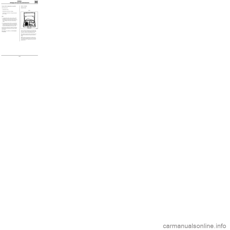
XR25
88-11
Page 75 of 83
WIRING
Airbags and seat belt pretensioners
88
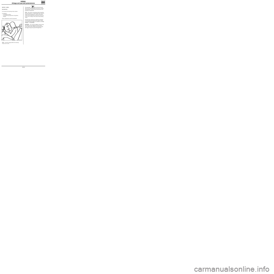
DRIVER’S AIRBAG
DESCRIPTION
It is located in the steering wheel cushion.
It comprises:
- an inflatable cushion,
- a pyrotechnic gas generator and ignition
module.
These components cannot be separated.
96310-1S
NOTE : when the airbag inflates, the steering
wheel cover is torn.Warning light on the instrument panel
shows the correct operation of the driver’s airbag,
the passenger’s airbag and the pretensioners (de-
pending on equipment).
NOTE : this system is operational after the ignition
has been turned on. A vehicle fitted with a driver’s
airbag will be identified by a label in the bottom
corner of the windscreen on the driver’s side, and
by the word "Airbag" in the centre of the steering
wheel.
Each time the windscreen is replaced, remember
to fit the labels showing that the vehicle is fitted
with airbags.These labels are available in a kit Part
Number : 77 01 205 442.
REMINDER : The computer must be replaced after
the airbag has been triggered. Certain compo-
nents will lose their nominal characteristics after
the trigger energy has passed through them.
88-20
Page 76 of 83
WIRING
Airbags and seat belt pretensioners
88
12973R
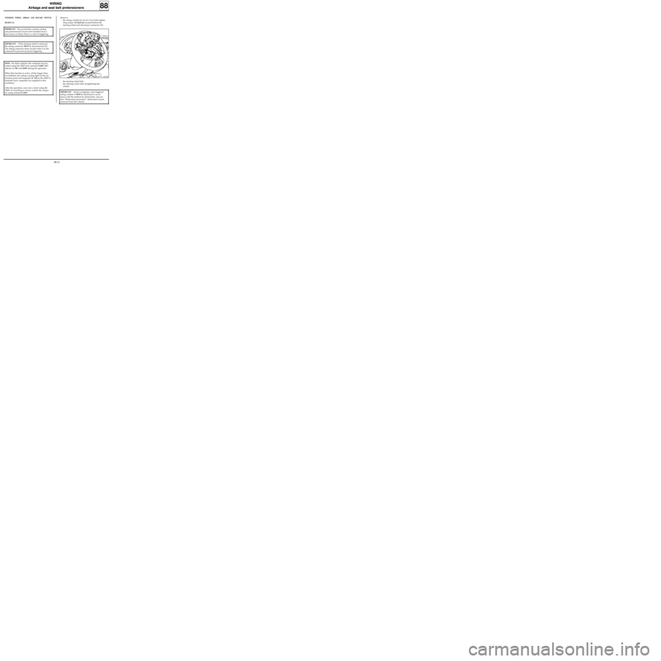
Remove:
- the airbag cushion by its two Torx bolts (tighte-
ning torque: 0.5 daN.m) located behind the
steering wheel and disconnect connector (D),
- the steering wheel bolt,
- the steering wheel after straightening the
wheels.
NOTE: For these vehicles, the computer may be
locked using the XR25 and command G80* (ISO
selector on S8 code D49) during the operation.
When this function is active, all the trigger lines
are inhibited, the airbag warning light on the ins-
trument panel and bargraph 14 LH on the XR25 il-
luminate (new computers are supplied in this
condition).
After the operation, carry out a check using the
XR25. If everything is correct, unlock the compu-
ter using command G81*.
IMPORTANT : before scrapping a non-triggered
airbag cushion it
MUST be destroyed in accor-
dance with the method for destruction (see sec-
tion "Destruction procedure": destruction of part
removed from the vehicle).
STEERING WHEEL AIRBAG AND ROTARY SWITCH
REMOVAL
IMPORTANT: The pyrotechnic systems (airbag
and pretensioners) must not be handled near a
heat source or flame; there is a risk of triggering.
IMPORTANT : If the steering wheel is removed,
the airbag connector
MUST be disconnected (D) .
The airbag connector short circuits when it is dis-
connected to prevent incorrect triggering.
88-21
Page 77 of 83
WIRING
Airbags and seat belt pretensioners
88
PRD99529
If it is being replaced, the new part is supplied rea-
dy centred by an adhesive label which will tear off
as soon as the steering wheel is turned for the first
time (fit with the wheels straight).
REFITTING
Ensure the wheels are still straight.
Ensure the rotary switch under the steering wheel
is still immobilised before refitting.
If this is not the case, follow the centring method
described below:
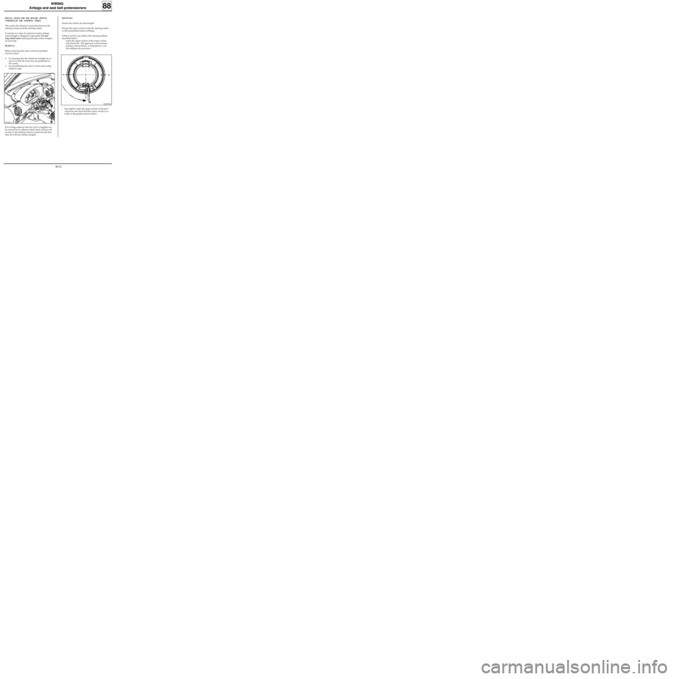
- rotate the upper section of the rotary switch
anti-clockwise. The approach to the extreme
position, shown below, is indicated by a cer-
tain stiffness (do not force).
SPECIAL NOTES FOR THE ROTARY SWITCH
UNDERNEATH THE STEERING WHEEL
This makes the electrical connection between the
steering column and the steering wheel.
It consists of a strip of conductor tracks (airbag)
whose length is designed to guarantee 2.5 stee-
ring wheel turns (steering lock plus safety margin)
on each side.
REMOVAL
Before removing the rotary switch its position
must be noted:
• by ensuring that the wheels are straight on re-
moval so that the track may be positioned in
the centre,
• by immobilising the rotary switch rotor using
adhesive tape.
- then lightly rotate the upper section of the part
clockwise and check that the rotary switch is ac-
tually in the position shown below.
12970R4
88-22
Page 78 of 83
WIRING
Airbags and seat belt pretensioners
88
IMPORTANT :
When everything has been refitted:
• Carry out a check using the XR25 to ensure that
there is no fault in the system.
• Unlock the computer with command G81* .
• Check that the airbag warning light illuminates
for 3 seconds after the ignition is switched on
then extinguishes and remains extinguished.
If the warning light does not operate as described
above, refer to the "Fault finding" section and
check the system using the XRBAG (Elé. 1288) or
XR25.
IMPORTANT:
If these procedures are not correctly observed the
systems may not operate correctly or may be
accidentally triggered.
PRD99530
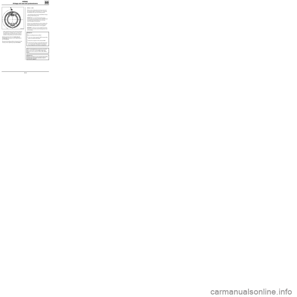
- again rotate the part in the clockwise direction
by making two complete turns, and after this
operation make sure that the rotary switch is
actually in the position previously described.
Refit the steering wheel and replace the pre-
bonded bolt, ensuring its correct tightening tor-
que (4.5 daN.m).
Reconnect the airbag cushion and secure it to the
steering wheel, tightening torque (0.5 daNm).
SPECIAL CASES
Where work is being done involving removal of
the steering, engine, transmission, etc., requiring
uncoupling of the rack and steering column:
→ the steering wheel must be immobilised using a
"steering wheel locking" tool.
IMPORTANT: to avoid destroying the rotary
switch under the steering wheel it is IMPORTANT
to maintain the fixed position of the steering
wheel throughout the operation.
If there is any doubt about its correct centring the
steering wheel must be removed so that the cen-
tring method described above can be applied.
REMINDER: in this case, only qualified personnel
who have received the correct training must work
on the airbag.
88-23