check engine light RENAULT KANGOO 1997 KC / 1.G Electrical Equipment Workshop Manual
[x] Cancel search | Manufacturer: RENAULT, Model Year: 1997, Model line: KANGOO, Model: RENAULT KANGOO 1997 KC / 1.GPages: 83
Page 13 of 83

IMMOBILISER
Coded key immobiliser system
DESCRIPTION
With this system the engine immobiliser is activa-
ted 10 seconds after switching off the ignition
(shown by the flashing of the red engine immobi-
liser warning light).
The system comprises:
• two key heads fitted with either:
- a single coded chip for controlling the immo-
biliser (A),
82
Opening a key head
Place the key head on a table with the metal in-
sert facing downwards.
Use a small screwdriver as a lever as shown below,
ensuring that the end of the screwdriver is placed
on the lower section (E) of the key head. This al-
lows the upper section to slide off the lower sec-
tion.
13078R
- a coded chip (A) for controlling the immo-
biliser and the electronic unit for the re-
mote control (B) allowing the opening
elements to be locked or unlocked (de-
pending on equipment).
13076R
13077R
NOTE : To remove the metal insert, move the re-
taining tab aside before removing it. When refit-
ting, check the insert is correctly clipped into posi-
tion.
82-2
Page 18 of 83

5.Check the immobiliser system operates cor-
rectly with both keys.
Ignition off, the red immobiliser warning light
should flash 10 seconds after switching the
ignition off (slow flashing). Bargraph
10 LH
should be illuminated. The vehicle should not
start when other keys are used.
NOTE : to simulate prevention from starting,
before switching the ignition on, wait for the
red warning light to flash slowly.
Enter on
the XR25, ignition still off (bargraph
9 LH illu-
minates).
Switch the ignition on, the red immobiliser
warning light should flash more quickly and
the vehicle should be impossible to start.
6.The procedure is complete. After switching
the ignition off and on again (for more than 2
seconds), check that the vehicle can be started
with both keys.
Diesel configuration
On diesel vehicles the decoder unit must be confi-
gured in "diesel" using the XR25.
1.Ignition off, XR25 connected (ISO selector on
S8).
Enter code (fiche n° 56),
bargraph
1 RH must be illuminated.
2.Enter programming mode
Bargraph
3 RH must illuminate.
The configuration is complete.
IMMOBILISER
Coded key immobiliser system
PROGRAMMING PROCEDURE
The procedure is carried out using one key.
The XR25 must be used for this procedure to lock
the key programming.
1.Ignition off, connect the XR25 to the vehicle
and set the selector to S8.
Enter code (fiche n° 56),
bargraphs 19 RH and 19 LH must be illumina-
ted (programming not carried out). If both of
these bargraphs are not illuminated, replace
the decoder unit (this unit has already been
used).
2.With one of the keys switch the ignition on
for approximately 2 seconds (without starting
the engine). Bargraph 18
LH illuminates and
bargraph
19 LH extinguishes.
The red immobiliser warning light flashes.
3.Switch the ignition off and start command
G60* to lock the programming. The red immo-
biliser warning light should flash (slow flas-
hing). Bargraphs 19 RH and 18 LH should be
extinguished.
4.Switch the ignition on for a few seconds (wi-
thout starting the engine) to send the code to
the injection computer or the coded solenoid
valve.
82
G2*2*
D56
G04*
D56
2
82-7
Page 19 of 83

5.Connect the XR25, setting the ISO selector to
S8.
Enter code
Bargraphs
19 RH and 19 LH must be illumina-
ted (programming not carried out).
6. With one of the keys switch the ignition on
for approximately 2 seconds (without star-
ting the engine). Bargraph 18
LH illuminates
and bargraph
19 LH extinguishes.
The red immobiliser warning light flashes rapi-
dly.
7.Switch the ignition off and start command
G60* to lock the programming.
- the red immobiliser warning light should
flash (slow flashing)
- bargraphs 19 RH and 18 LH should be ex-
tinguished.
8.Switch the ignition on for a few seconds,
check that the red immobiliser warning light
is illuminated permanently (diesel) or that
the injection warning light is flashing (pe-
trol).
9.Switch the ignition on for more than 10
consecutive seconds.
10.Switch the ignition off and wait for the red
immobiliser warning light to flash slowly.
Enter command
with the ignition still off (bargraph
9 LH illu-
minates).
Switch the ignition on, the red immobiliser
warning light flashes more rapidly.
Follow the procedure for entering the securi-
ty code (see procedure for entering the secu-
rity code), using the code number correspon-
ding to the old kit. This erases the old code
memorised in the injection computer or the
coded solenoid valve.
IMMOBILISER
Coded key immobiliser system
REPLACING A KIT
(decoder unit plus two key heads)
If a kit is replaced it will be necessary to:
- programme the codes of the 2 new keys in the
new decoder unit (supplied uncoded).
- erase the old code in the injection computer or
coded solenoid valve using the security proce-
dure (the code number for the old kit should be
requested from the local assistance network,
example Delta Assistance for France, NVSR for
the UK by fax only)
IMPORTANT : to erase the old code (memorised in
the injection computer or coded solenoid valve
electronic unit), the procedure described below
must be followed in the correct order.
The code in the injection computer or coded sole-
noid valve cannot be erased with the security code
(using the number for the old kit) unless the deco-
der unit fitted to the vehicle has been program-
med with a different code (which is the case in the
following procedure).
NOTE : if the security code is entered when the
decoder unit has the same code as the injection
computer, or coded solenoid valve, it will not be
decoded.
1.Fit the metal inserts from the old keys into
the new key heads.
2.Note the number of one of the old keys to
obtain the security code number.
3.Remove the decoder unit with the ignition
off.
4.Fit the new decoder unit, ignition off.
82
G04*
D56
82-8
Page 20 of 83

11. Switch the ignition off and on again for a few
seconds without starting the engine to pro-
gramme the immobiliser code for the new kit
in the injection computer or coded solenoid
valve. The red warning light should illuminate
for 3 seconds then extinguish.
For diesel :
Ignition off, configure the decoder unit to
"diesel" (see diesel configuration using command
)
Bargraph
3 RH should illuminate; the configura-
tion is complete.
NOTE
- petrol vehicles: Using the XR25, check the in-
jection computer has been programmed with
the code. Bargraph
2 RH (immobiliser) should
be extinguished.
After entering
the display should show
The injection computer has been correctly co-
ded.
If the display shows
the injection computer is still uncoded.
- diesel vehicles: When the ignition is switched
on, check the immobiliser warning light extin-
guishes after 3 seconds.
IMMOBILISER
Coded key immobiliser system
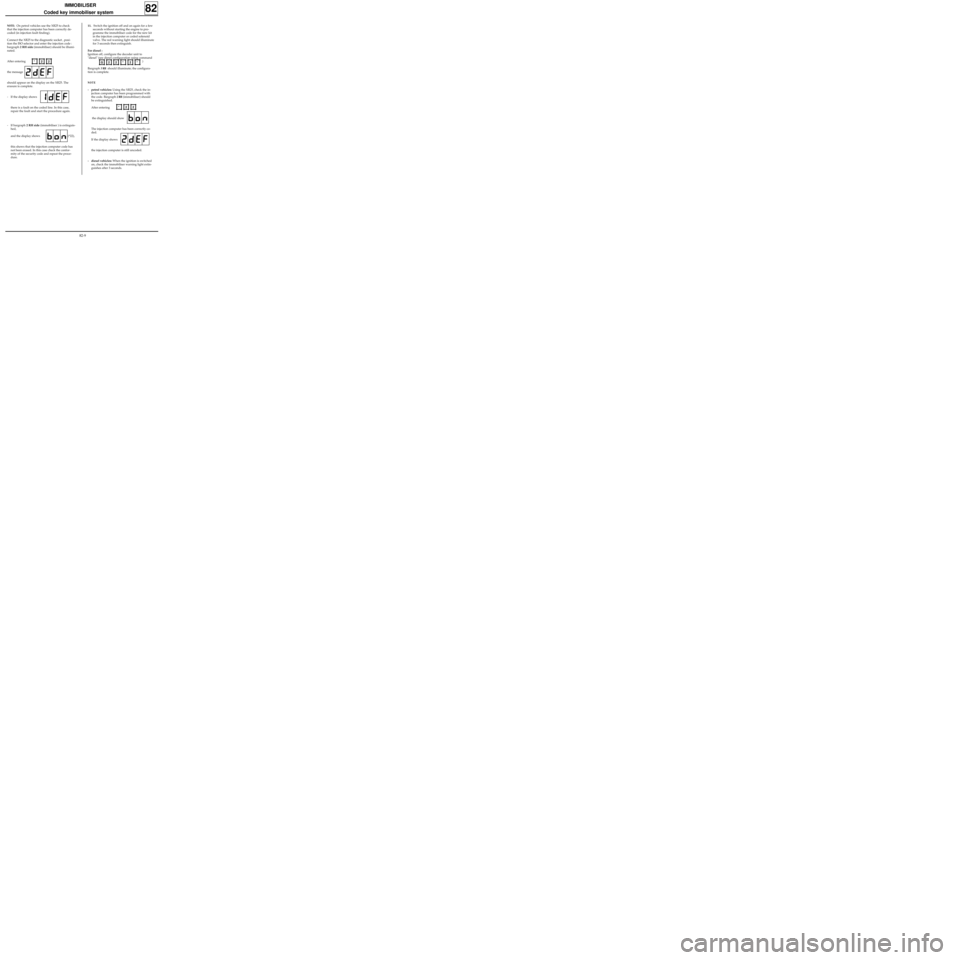
NOTE: On petrol vehicles use the XR25 to check
that the injection computer has been correctly de-
coded (in injection fault finding).
Connect the XR25 to the diagnostic socket , posi-
tion the ISO selector and enter the injection code :
bargraph 2 RH side (immobiliser) should be illumi-
nated.
After entering
the message
should appear on the display on the XR25. The
erasure is complete.
- If the display shows
there is a fault on the coded line. In this case,
repair the fault and start the procedure again.
- If bargraph 2 RH side (immobiliser ) is extinguis-
hed,
and the display shows (*22),
this shows that the injection computer code has
not been erased. In this case check the confor-
mity of the security code and repeat the proce-
dure.
82
*22G22*2*
*22
82-9
Page 21 of 83

REPLACING THE INJECTION COMPUTER OR
CODED SOLENOID VALVE
The injection computer and coded solenoid valve
are supplied uncoded. The engine immobiliser
code must be programmed in when they are fit-
ted.
It is sufficient to carry out the following opera-
tions:
- switch the ignition on, without starting the en-
gine, using the vehicle’s coded key for a few
seconds,
- switch the ignition off, the immobiliser will be
activated approximately 10 seconds afterwards
(red immobiliser warning light flashes).
NOTE : starting prevention can be checked
using the XR25:
- Ignition off, wait for the warning light to
flash (slow flashing)
Enter
ignition still off (bargraph
9 LH illuminates).
- Switch the ignition on, the red immobiliser
warning light should flash more quickly and
the vehicle should be impossible to start.
NOTE : For removal - refitting information, refer
to the corresponding section (13 or 17).
IMMOBILISER
Coded key immobiliser system
12.Check the immobiliser system operates cor-
rectly with both keys.
Switch the ignition on and check that the red
warning light illuminates for 3 seconds then
extinguishes and that the vehicle can be star-
ted.
NOTE : starting prevention can be checked
using the XR25:
- Ignition off, wait for the warning light to
flash (slow flashing)
Enter
- Switch the ignition on and check the vehi-
cle cannot be started and that the red war-
ning light flashes (rapid flashing).
13.The procedure is complete. After turning the
ignition off and on again (for more than 2 se-
conds), check the vehicle can be started and
erase all faults present in the decoder unit.
Vehicles fitted with a remote control
After replacing the kit carry out a resynchronisa-
tion operation (see simple resynchronisation pro-
cedure, section 88).
82
G04*
G04*
82-10
Page 34 of 83

INSTRUMENT PANEL
Instrument panel
83
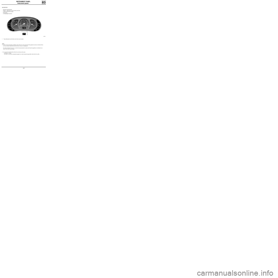
DESCRIPTION
- electronic speedometer,
- display : mileometer/trip recorder and clock
- coolant temperature gauge,
- fuel gauge,
- warning light functions.
13054S
1 Trip mileometer reset button and clock reset (rotate).
NOTE :
• Under normal operating conditions, the oil level is only measured if the ignition has been switched off for
over one minute; otherwise the old oil level value is re-displayed.
If a fault is detected, however, an oil level measurement is made each time the ignition is switched on to
check if the fault is persisting.
• It is normal to find that the oil level is not always the same:
- parking on a slope,
- too short a wait after running the engine for a short moment (especially when the oil is cold), ...
83-7
Page 39 of 83

INSTRUMENT PANEL
Oil level sensor
83
98898R1
OPERATION
The sensor consists of a wire with a high
coefficient of resistance. When a current passes
through the wire it does not have the same
thermal conductivity when it is immersed in a
liquid as when it is in the open air.
After a fixed time a voltage difference is obtained
at the sensor terminals depending on the depth of
immersion of the wire. This voltage difference is
recorded by the electronic unit which manages
the level display function and also controls the
"low oil level" warning light display on the
central liquid crystal display.
When the ignition is switched on, the central dis-
play shows the oil level in a series of "blocks" for
approximately 30 seconds, before returning to
displaying the trip mileometer and total mileome-
ter functions (or "odometer" function).
NOTE : Turning the trip mileometer reset button
before the end of the timed period will display
the "odometer" function.
LOOKING FOR FAULTS
If a short circuit or an open circuit is detected
when the oil level is measured, the display will im-
mediately show the trip mileometer / clock dis-
plays.
CHECKING
The sensor resistance must be between 6 and 20
ohms.
The sensor is deemed to be in short circuit for a va-
lue lower than 4 ohms.
The sensor is deemed to be in open circuit for a va-
lue higher than 22 ohms.
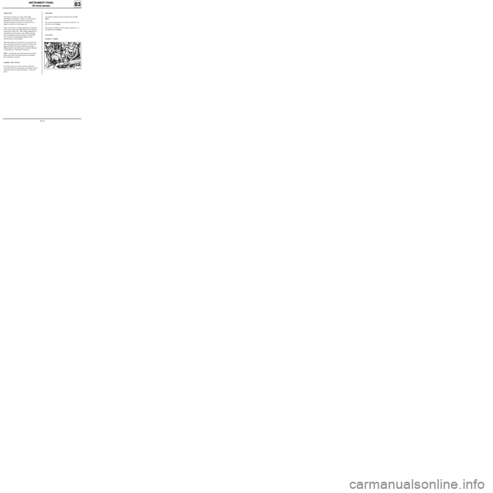
LOCATION
Example : F engine
83-12
Page 40 of 83

INSTRUMENT PANEL
Coolant temperature sensor
F engine
83
12535R1
OPERATION
A thermistor transmits a variation in resistance to
a receiver, depending on the coolant
temperature, and a threshold overshoot switch
illuminates the warning light on the instrument
panel when the temperature reaches 118°C.
CHECKING
Connect an ohmmeter between track 1 (K and E
engines) or track 2 (F engine) on the sensor and
vehicle earth.
Correct value : 160 to 1 250 Ω.
LOCATION
D engine
E engine
98711R4
11634R3
1 Warning light sensor
2 Gauge sensor
83-13
Page 78 of 83

WIRING
Airbags and seat belt pretensioners
88
IMPORTANT :
When everything has been refitted:
• Carry out a check using the XR25 to ensure that
there is no fault in the system.
• Unlock the computer with command G81* .
• Check that the airbag warning light illuminates
for 3 seconds after the ignition is switched on
then extinguishes and remains extinguished.
If the warning light does not operate as described
above, refer to the "Fault finding" section and
check the system using the XRBAG (Elé. 1288) or
XR25.
IMPORTANT:
If these procedures are not correctly observed the
systems may not operate correctly or may be
accidentally triggered.
PRD99530
- again rotate the part in the clockwise direction
by making two complete turns, and after this
operation make sure that the rotary switch is
actually in the position previously described.
Refit the steering wheel and replace the pre-
bonded bolt, ensuring its correct tightening tor-
que (4.5 daN.m).
Reconnect the airbag cushion and secure it to the
steering wheel, tightening torque (0.5 daNm).
SPECIAL CASES
Where work is being done involving removal of
the steering, engine, transmission, etc., requiring
uncoupling of the rack and steering column:
→ the steering wheel must be immobilised using a
"steering wheel locking" tool.
IMPORTANT: to avoid destroying the rotary
switch under the steering wheel it is IMPORTANT
to maintain the fixed position of the steering
wheel throughout the operation.
If there is any doubt about its correct centring the
steering wheel must be removed so that the cen-
tring method described above can be applied.
REMINDER: in this case, only qualified personnel
who have received the correct training must work
on the airbag.
88-23