suspension RENAULT KANGOO 1997 KC / 1.G Engine And Peripherals Workshop Manual
[x] Cancel search | Manufacturer: RENAULT, Model Year: 1997, Model line: KANGOO, Model: RENAULT KANGOO 1997 KC / 1.GPages: 208
Page 1 of 208

Renault 1997
77 11 194 226JULY 1997Edition anglaise
"The repair methods given by the manufacturer in this document are based on the
technical specifications current when it was prepared.
The methods may be modified as a result of changes introduced by the
manufacturer in the production of the various component units and accessories
from which his vehicles are constructed"All copyrights reserved by Renault.
Copying or translating, in part or in full , of this document or use of the service part
reference numbering system is forbidden without the prior written authority of
Renault.
C
FC0A - FC0C - FC0D - FC0E - KC0A - KC0C - KC0D - KC0E
Engine and peripherals
ENGINE AND PERIPHERALS
TOP AND FRONT OF ENGINE
FUEL MIXTURE
FUEL SUPPLY -
DIESEL EQUIPMENT
ANTIPOLLUTION
STARTING - CHARGING
IGNITION - INJECTION
COOLING - EXHAUST - FUEL TANK -
ENGINE SUSPENSION
Page 4 of 208

Page
Cooling
Specifications
Filling and bleeding
Testing
Diagram
Water pump
Exhaust
General
Exhaust pipe assembly
Fuel tank
Tank
Sender unit
Pump and sender unit assembly
Engine suspension
Suspended engine mountings19-1
19-2
19-3
19-4
19-7
19-12
19-15
19-17
19-29
19-30
19-32 COOLING - EXHAUST - FUEL TANK -
ENGINE SUSPENSION
19
16-1
16-7 STARTING - CHARGING
Alternator
Starter
16
IGNITION - INJECTION
Ignition
Static ignition
Plugs
Injection
General
Location of components
Centralised coolant temperature
management
Injection fault warning light
Immobiliser function
Computer configuration depending
on gearbox type17
14-1
14-2
14-7
14-11 ANTIPOLLUTION
Test for the presence of lead
Fuel vapour rebreathing
Oil vapour rebreathing
Exhaust gas recirculation
(EGR)
14
17-17
17-18
17-19
17-20
17-22 IGNITION - INJECTION
(continued)
Injection/air conditioning
programming
Idle speed correction
Adaptive idle speed
correction
Richness regulation
Adaptive richness correction
17
Page
17-1
17-3
17-4
17-8
17-13
17-14
17-15
17-16
Contents
Page 18 of 208

ENGINE AND ENGINE PERIPHERALS
Engine and transmission assembly
10
Front sub-frame mounting bolt 6.2
Rear sub-frame mounting bolt 10.5
Mounting bolt for front right suspended
engine mounting cover on engine 6.2
Mounting nut for front right suspended
engine mounting cover 4.4
Mounting nut for rubber engine mounting pad
on front left-hand side member support 6.2
Shock absorber base bolt 18
Brake caliper mounting bolt 4
Steering shaft yoke bolt 3
Wheel bolt 9
TIGHTENING TORQUES (in daN.m)
REMOVAL
Put the vehicle on a 2 post lift.
Disconnect the battery.
Drain:
- the cooling circuit through the bottom hose
of the radiator,
- the gearbox and the engine if necessary.
Remove:
- the bonnet,
- the front wheels,
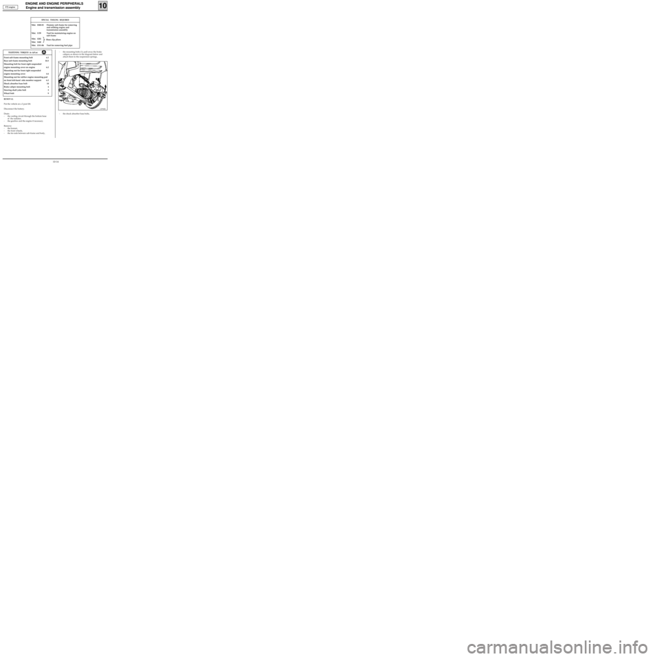
- the tie-rods between sub-frame and body,- the mounting bolts (1); pull away the brake
calipers as shown in the diagram below and
attach them to the suspension springs,
12994R1
- the shock absorber base bolts, E7J engine
SPECIAL TOOLING REQUIRED
Mot. 1040-01 Dummy sub-frame for removing
and refitting engine and
transmission assembly
Mot. 1159 Tool for maintaining engine on
sub-frame
Mot. 1202
Mot. 1448
Mot. 1311-06 Tool for removing fuel pipe
Hose clip pliers
10-14
Page 23 of 208

ENGINE AND ENGINE PERIPHERALS
Engine and transmission assembly
10
SPECIAL TOOLING REQUIRED
Mot. 1040-01 Dummy sub-frame for removing -
refitting the engine and
transmission assembly
Mot. 1159 Tool for maintaining engine on
sub-frame
Mot. 1202
Mot. 1448
Mot. 1311-06 Tool for removing fuel pipe
Front sub-frame mounting bolt 6.2
Rear sub-frame mounting bolt 10.5
Mounting bolt for front right suspended engine
mounting cover on engine 6.2
Mounting nut for front right suspended engine
mounting cover 4.4
Mounting nut for rubber engine mounting
pad on front left side member support 6.2
Shock absorber base bolt 18
Brake caliper mounting bolt 4
Steering shaft yoke bolt 3
Wheel bolt 9
TIGHTENING TORQUES (in daN.m)
REMOVAL
Put the vehicle on a 2 post lift.
Disconnect the battery.
Drain:
- the cooling circuit through the bottom hose
of the radiator,
- the gearbox and the engine if necessary.
Remove:
- the bonnet,
- the front wheels,
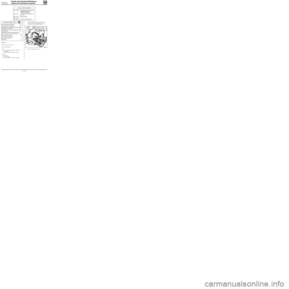
- the tie-rods between sub-frame and body,- the mounting bolts (1); pull away the brake
calipers as shown in the diagram below and
attach them to the suspension springs,
12994R1
- the shock absorber base bolts, F8Q engine
Hose clip pliers
10-19