RENAULT KANGOO 1997 KC / 1.G Foult Finding - Injection Workshop Manual
Manufacturer: RENAULT, Model Year: 1997, Model line: KANGOO, Model: RENAULT KANGOO 1997 KC / 1.GPages: 363
Page 291 of 363
B76531.0
ELECTRONICALLY CONTROLLED HYDRAULIC SYSTEM
Fault finding - Fault chart 38
ABS BOSCH
5.3
AFTER REPAIR Carry out a road test, then a check with the XR25 kit.
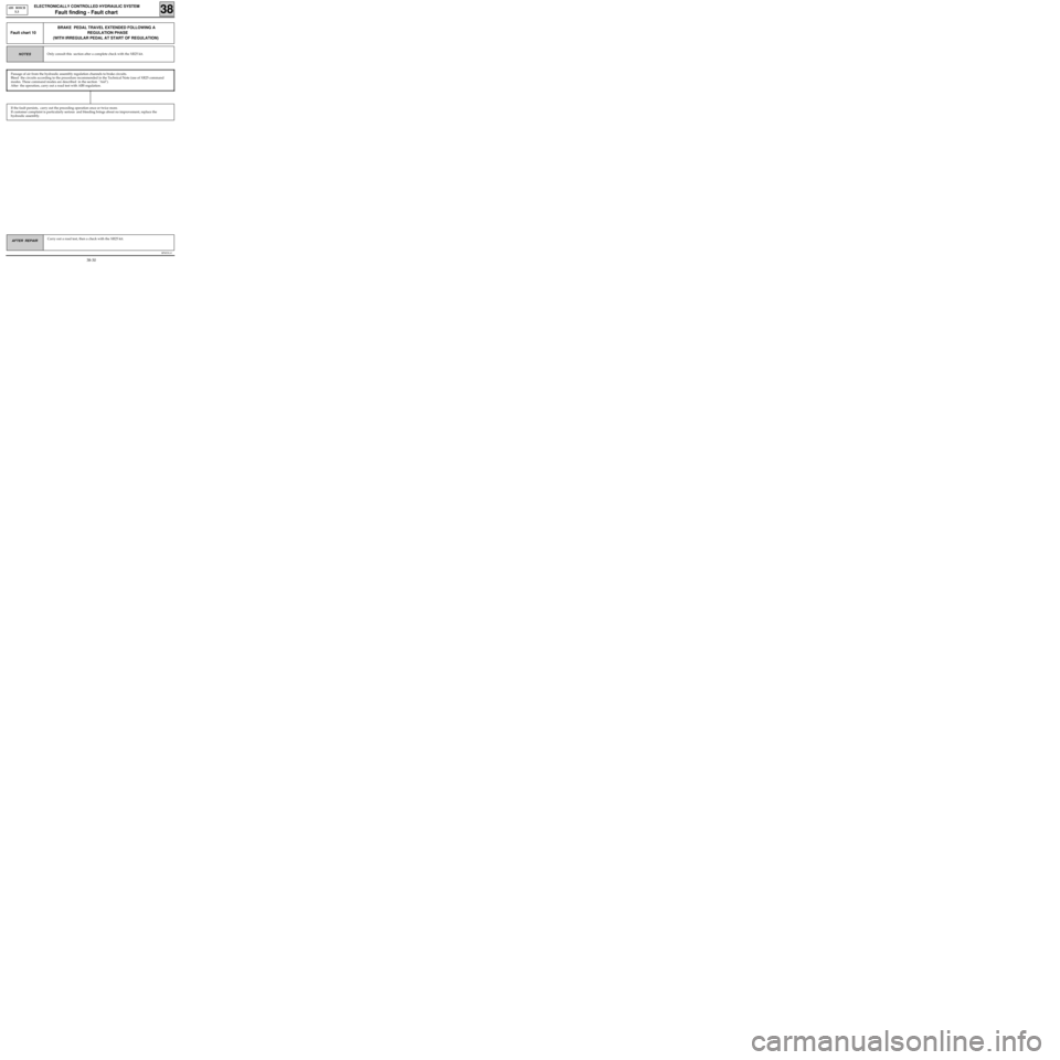
BRAKE PEDAL TRAVEL EXTENDED FOLLOWING A
REGULATION PHASE
(WITH IRREGULAR PEDAL AT START OF REGULATION)
Fault chart 10
Passage of air from the hydraulic assembly regulation channels to brake circuits.
Bleed the circuits according to the procedure recommended in the Technical Note (use of XR25 command
modes. These command modes are described in the section "Aid").
After the operation, carry out a road test with ABS regulation.
Only consult this section after a complete check with the XR25 kit.NOTES
If the fault persists, carry out the preceding operation once or twice more.
If customer complaint is particularly serious and bleeding brings about no improvement, replace the
hydraulic assembly.
38-30
Page 292 of 363
B76531.0
ELECTRONICALLY CONTROLLED HYDRAULIC SYSTEM
Fault finding - Fault chart 38
ABS BOSCH
5.3
AFTER REPAIR Carry out a road test, then a check with the XR25 kit.
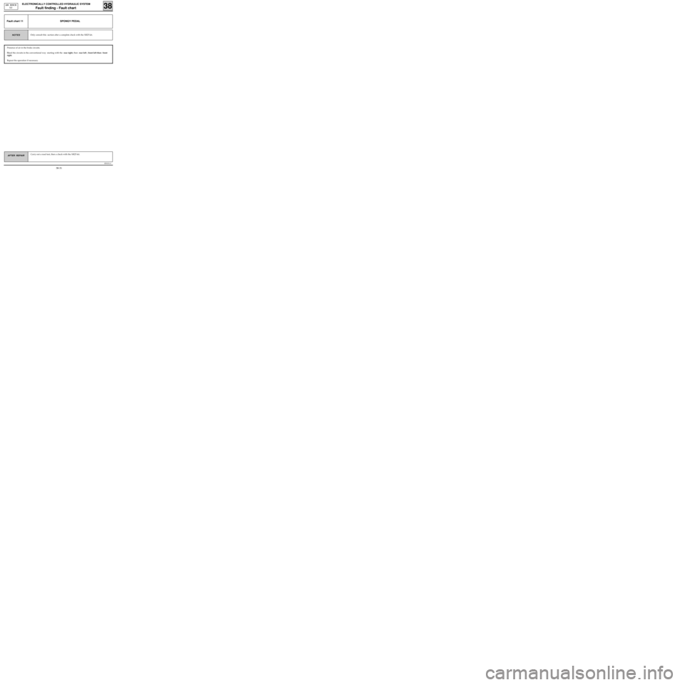
SPONGY PEDALFault chart 11
Presence of air in the brake circuits.
Bleed the circuits in the conventional way starting with the rear right, then rear left , front left then front
right.
Repeat the operation if necessary.
Only consult this section after a complete check with the XR25 kit.NOTES
38-31
Page 293 of 363
B76531.0
ELECTRONICALLY CONTROLLED HYDRAULIC SYSTEM
Fault finding - Fault chart 38
ABS BOSCH
5.3
AFTER REPAIR Carry out a road test, then a check with the XR25 kit.
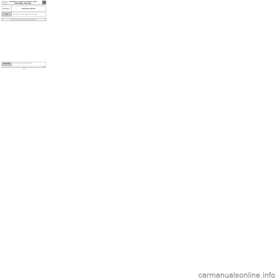
BRAKE PEDAL VIBRATIONFault chart 12
Normal reaction of the brake pedal during an ABS regulation phase.
Only consult this section after a complete check with the XR25 kit.NOTES
38-32
Page 294 of 363
B76531.0
ELECTRONICALLY CONTROLLED HYDRAULIC SYSTEM
Fault finding - Fault chart 38
ABS BOSCH
5.3
AFTER REPAIR Carry out a road test, then a check with the XR25 kit.
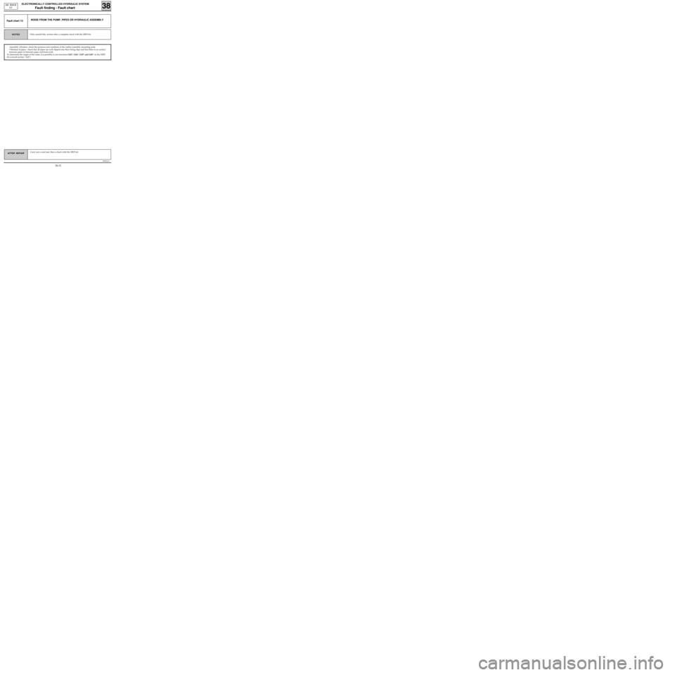
NOISE FROM THE PUMP, PIPES OR HYDRAULIC ASSEMBLYFault chart 13
- Assembly vibration: check the presence and condition of the rubber assembly mounting pads.
- Vibration of pipes : check that all pipes are well clipped into their fixing clips and that there is no contact
between pipes or between pipes and bodywork.
To determine the origin of the noise, it is possible to use functions G03*, G04*, G05* and G06* on the XR25
kit (consult section "Aid").
Only consult this section after a complete check with the XR25 kit.NOTES
38-33
Page 295 of 363
B76531.0
ELECTRONICALLY CONTROLLED HYDRAULIC SYSTEM
Fault finding - Fault chart 38
ABS BOSCH
5.3
AFTER REPAIR Carry out a road test, then a check with the XR25 kit.
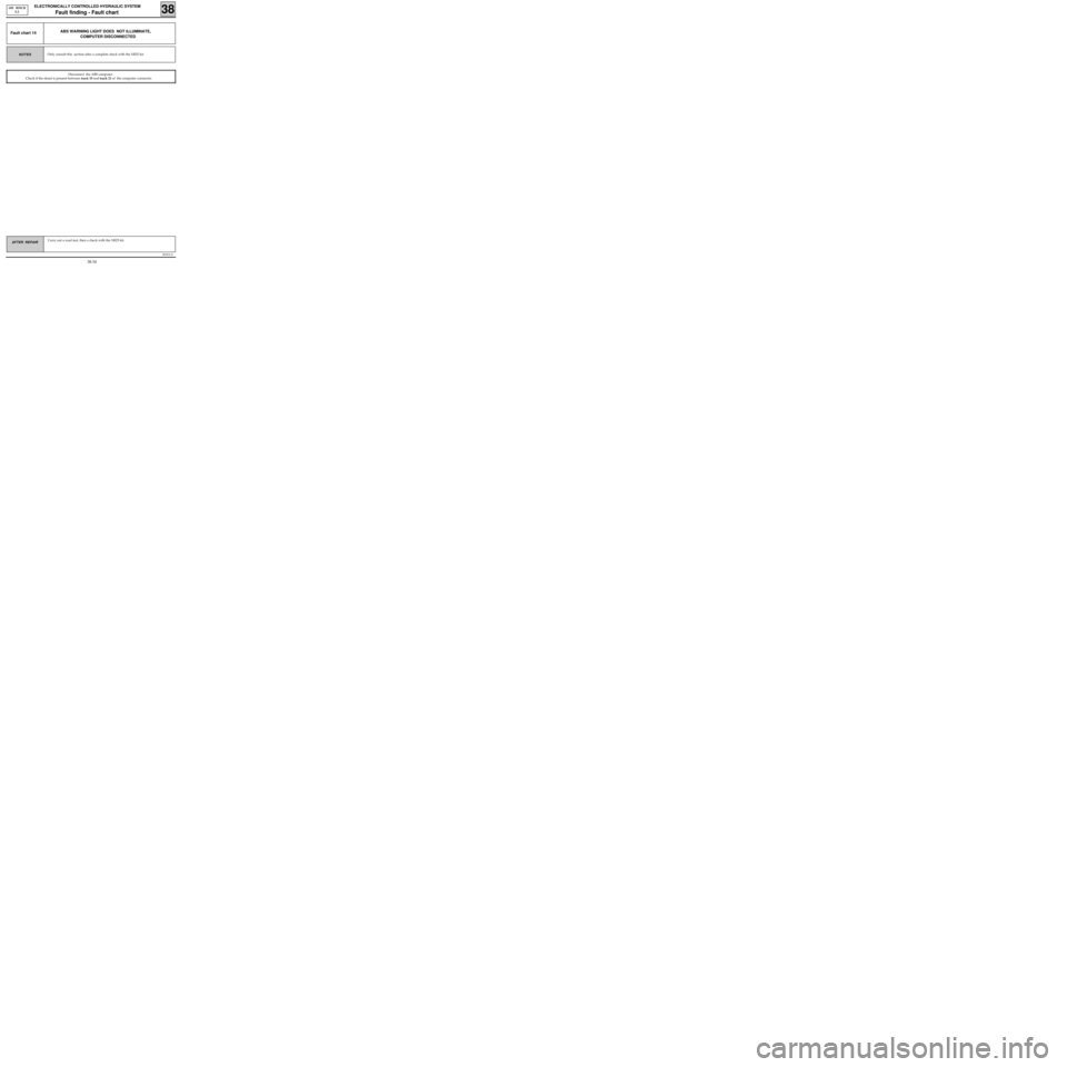
ABS WARNING LIGHT DOES NOT ILLUMINATE,
COMPUTER DISCONNECTEDFault chart 14
Disconnect the ABS computer .
Check if the shunt is present between track 19 and track 21 of the computer connector.
Only consult this section after a complete check with the XR25 kit.NOTES
38-34
Page 296 of 363
B76531.0
ELECTRONICALLY CONTROLLED HYDRAULIC SYSTEM
Fault finding - Fault chart 38
ABS BOSCH
5.3
AFTER REPAIR Carry out a road test, then a check with the XR25 kit.
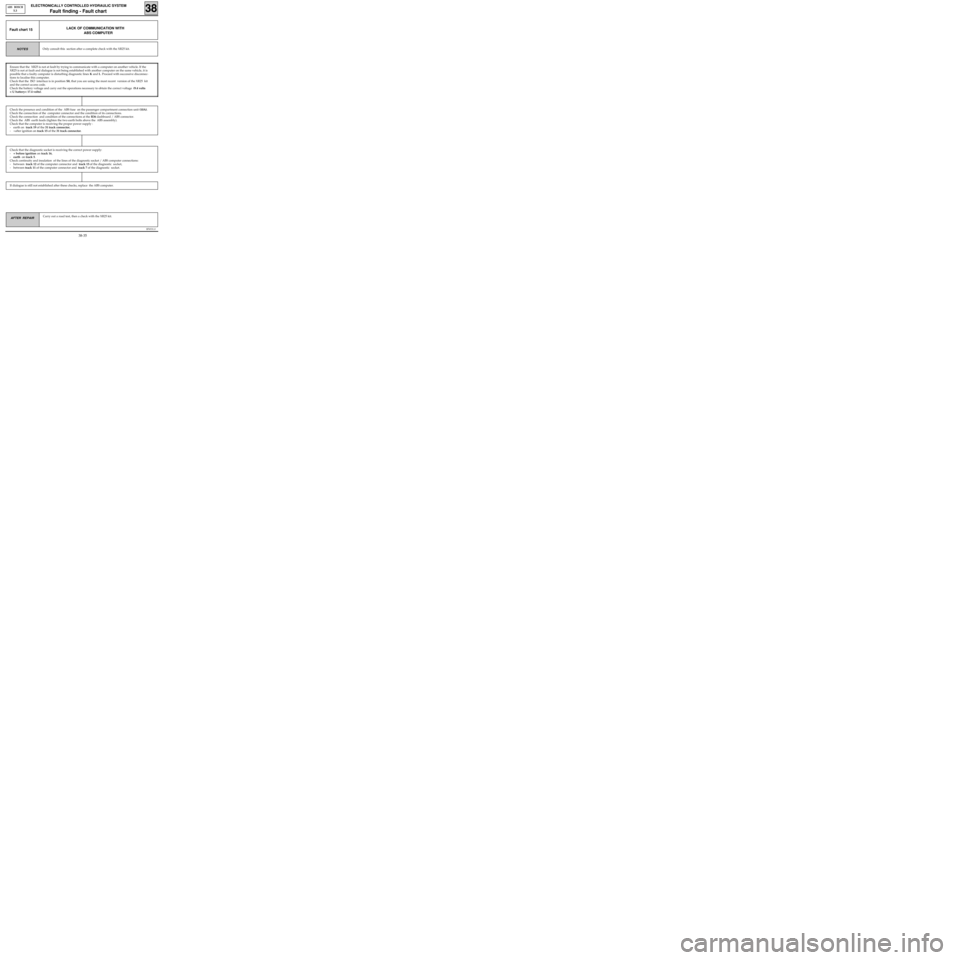
LACK OF COMMUNICATION WITH
ABS COMPUTERFault chart 15
Only consult this section after a complete check with the XR25 kit.NOTES
If dialogue is still not established after these checks, replace the ABS computer.
Check that the diagnostic socket is receiving the correct power supply:
-+ before ignition on track 16,
-earth on track 5.
Check continuity and insulation of the lines of the diagnostic socket / ABS computer connections:
- between track 12 of the computer connector and track 15 of the diagnostic socket,
- between track 11 of the computer connector and track 7 of the diagnostic socket.
Check the presence and condition of the ABS fuse on the passenger compartment connection unit (10A).
Check the connection of the computer connector and the condition of its connections.
Check the connection and condition of the connections at the R36 dashboard / ABS connector.
Check the ABS earth leads (tighten the two earth bolts above the ABS assembly).
Check that the computer is receiving the proper power supply :
- earth on track 19 of the 31 track connector,
- +after ignition on track 15 of the 31 track connector.
Ensure that the XR25 is not at fault by trying to communicate with a computer on another vehicle. If the
XR25 is not at fault and dialogue is not being established with another computer on the same vehicle, it is
possible that a faulty computer is disturbing diagnostic lines K and L. Proceed with successive disconnec-
tions to localise this computer.
Check that the ISO interface is in position S8, that you are using the most recent version of the XR25 kit
and the correct access code.
Check the battery voltage and carry out the operations necessary to obtain the correct voltage (9.4 volts
< U battery< 17.4 volts).
38-35
Page 297 of 363

IMMOBILISER
FAULT FINDING
SUMMARY
Introduction . . . . . . . . . . . . . . . . . . . . . . . . . . . . . . . . . . . . . . . . . . . . . . . . . . . . . . . . . . . . . . . . . . . . . . . . . . . . . . . . . 01
XR25 fiche . . . . . . . . . . . . . . . . . . . . . . . . . . . . . . . . . . . . . . . . . . . . . . . . . . . . . . . . . . . . . . . . . . . . . . . . . . . . . . . . . . . 02
Interpretation of XR25 bargraphs . . . . . . . . . . . . . . . . . . . . . . . . . . . . . . . . . . . . . . . . . . . . . . . . . . . . . . . . . . . . . . 04
Customer complaints (petrol version) . . . . . . . . . . . . . . . . . . . . . . . . . . . . . . . . . . . . . . . . . . . . . . . . . . . . . . . . . . 14
Fault charts (petrol version) . . . . . . . . . . . . . . . . . . . . . . . . . . . . . . . . . . . . . . . . . . . . . . . . . . . . . . . . . . . . . . . . . . . 15
Customer complaints (diesel version) . . . . . . . . . . . . . . . . . . . . . . . . . . . . . . . . . . . . . . . . . . . . . . . . . . . . . . . . . . . 25
Fault charts (diesel version) . . . . . . . . . . . . . . . . . . . . . . . . . . . . . . . . . . . . . . . . . . . . . . . . . . . . . . . . . . . . . . . . . . . . 26
Conformity check . . . . . . . . . . . . . . . . . . . . . . . . . . . . . . . . . . . . . . . . . . . . . . . . . . . . . . . . . . . . . . . . . . . . . . . . . . . . 34
Aid . . . . . . . . . . . . . . . . . . . . . . . . . . . . . . . . . . . . . . . . . . . . . . . . . . . . . . . . . . . . . . . . . . . . . . . . . . . . . . . . . . . . . . . . . 39Pages
Page 298 of 363
v0406.0
IMMOBILISER
Fault finding - Introduction
82
INSTALLATION OF XR25 DIALOGUE / DECODER UNIT
- Connect the XR25 to the diagnostic socket.
- ISO selector on S8
- Enter D56 n.56
PRECAUTION :
When carrying out the test using a multimeter, avoid using a test pin on connectors where the test pin is
of a size which could damage the clips and lead to a poor contact.
Pay attention to parts numbers on wrenches.
ERASING THE MEMORY
After repairing the immobiliser system, enter G0** on the keyboard of the XR25 kit to proceed with
erasing the memorised fault.
82-1
Page 299 of 363
v0406.0
IMMOBILISER
Fault finding- XR25 Fiche
82
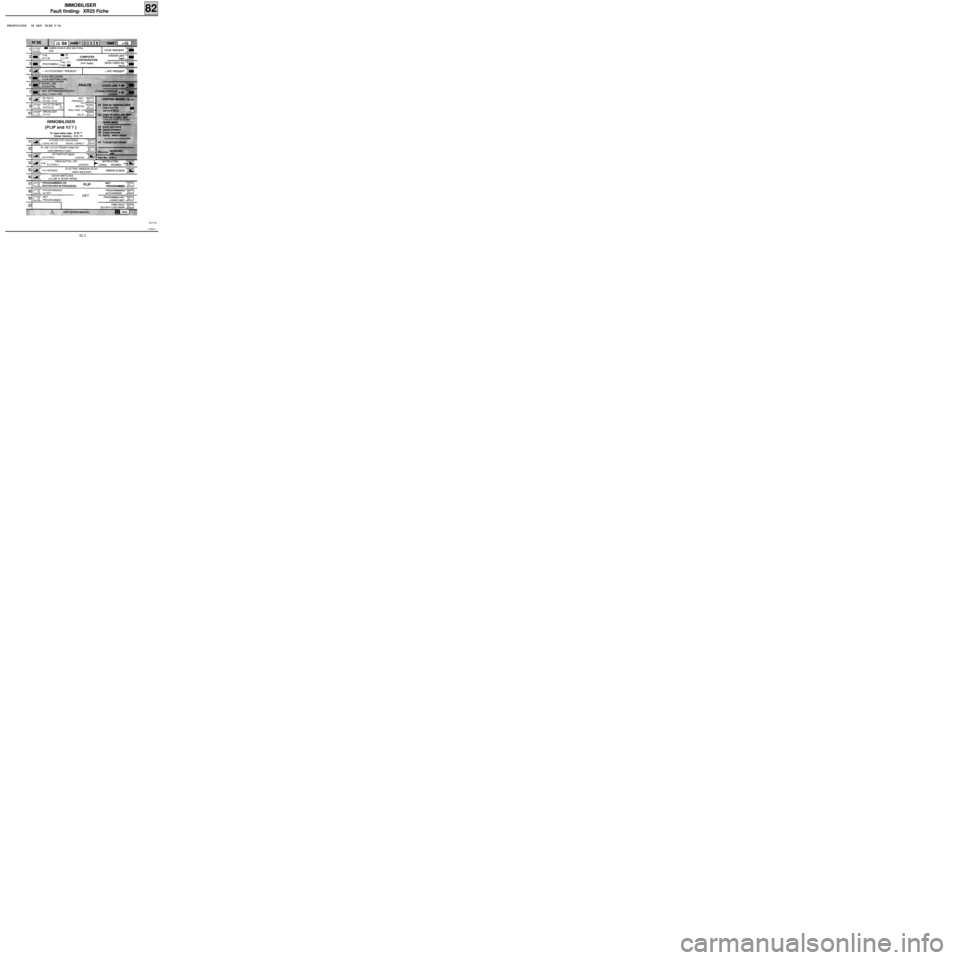
PRESENTATION OF XR25 FICHE N° 56
FI21756
82-2
Page 300 of 363
v0406.0
IMMOBILISER
Fault finding- XR25 Fiche
82
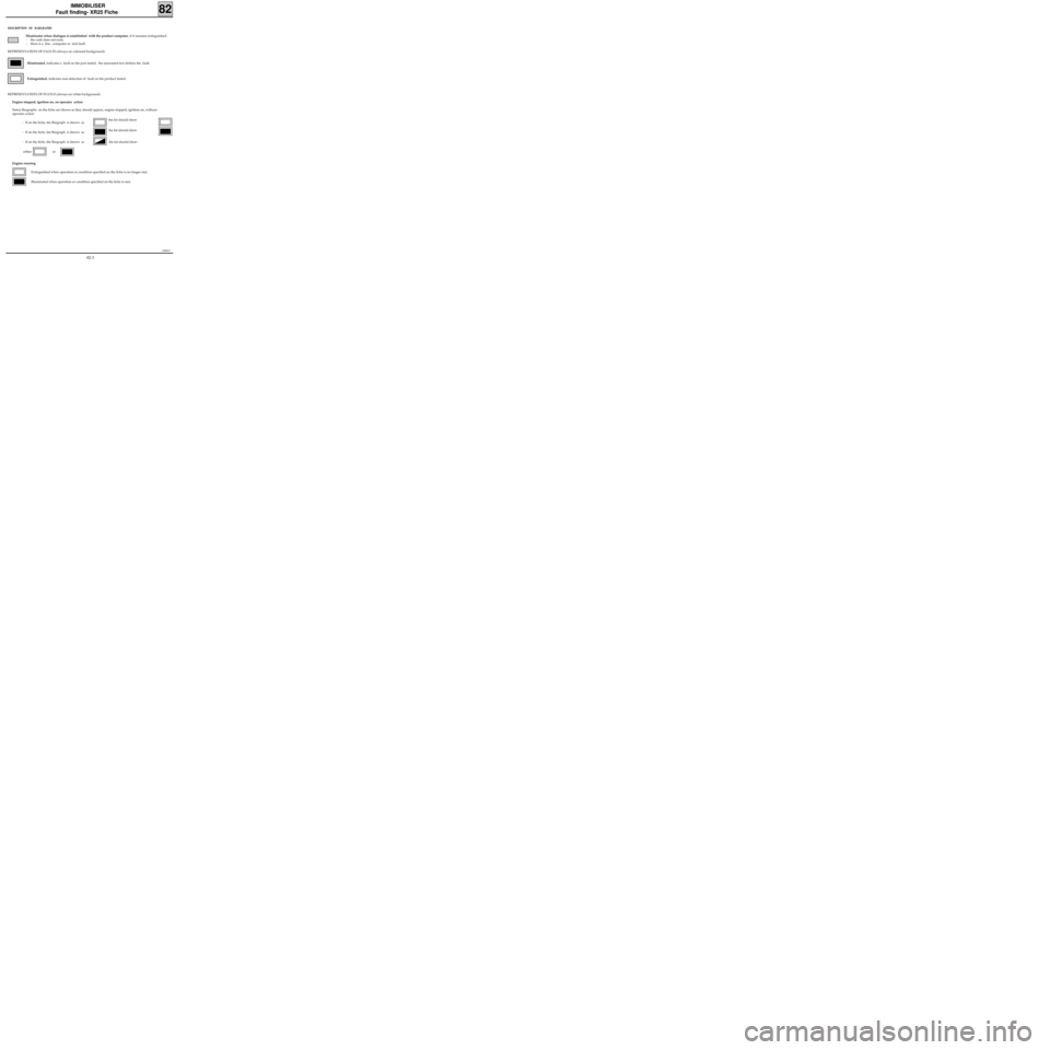
DESCRIPTION OF BARGRAPHS
Illuminates when dialogue is established with the product computer, if it remains extinguished :
- the code does not exist,
- there is a line , computer or tool fault.
REPRESENTATION OF FAULTS (always on coloured background)
Illuminated, indicates a fault on the part tested, the associated text defines the fault.
Extinguished, indicates non-detection of fault on the product tested.
REPRESENTATION OF STATUS (always on white background)
Engine stopped, ignition on, no operator action
Status Bargraphs on the fiche are shown as they should appear, engine stopped, ignition on, without
operator action
- If on the fiche, the Bargraph is shown as
- If on the fiche, the Bargraph is shown as
- If on the fiche, the Bargraph is shown as the kit should show
either or
Engine running
Extinguished when operation or condition specified on the fiche is no longer met.
Illuminated when operation or condition specified on the fiche is met.
the kit should show
the kit should show
82-3