air condition RENAULT SCENIC 2007 J84 / 2.G Anti Lock Braking System Bosch 8.0 ESP Owner's Guide
[x] Cancel search | Manufacturer: RENAULT, Model Year: 2007, Model line: SCENIC, Model: RENAULT SCENIC 2007 J84 / 2.GPages: 85, PDF Size: 0.29 MB
Page 45 of 85
ANTI-LOCK BRAKING SYSTEM
BOSCH 8.0 ESP Vdiag No.: 08, 09, 0A, 0B, 11, 1238C
38C - 45V2 MR-372-J84-38C050$496_eng.mif
BOSCH 8.0 ESP
Vdiag No.: 08, 09, 0A,
0B, 11, 12ANTI-LOCK BRAKING SYSTEM
DF126
PRESENT
OR
STOREDCOMBINED SENSOR SIGNAL PLAUSIBILITY
NOTESSpecial notes:
This fault means that the combined sensor signals are not consistent with the other
ESP sensors (steering wheel angle sensor and wheel speed sensors). If the fault
appears while the vehicle is being driven on a steep gradient, during a very tight turn
or while the vehicle is being transported on a lorry, train, boat, etc., with the engine
running, clear the fault and if possible check that the fault has disappeared by carrying
out a road test.
Conditions for applying the fault finding procedure to stored faults:
The fault is declared present during a road test.
Check the connection and condition of the combined sensor connector.
Ensure that the sensor is properly fixed to the body in the right direction (arrow pointing to the front of the vehicle).
Check the condition of the axle assemblies (impacts, damage, etc.) and the conformity and good condition of the
tyres.
Using the diagnostic tool, calibrate the steering wheel angle in the "Electric power steering" subgroup followed by
command RZ003 "ESP sensor programming" for Vdiag 09, 0A, 0B, 12 and 11 in the ABS/ESP.
Re-establish dialogue with the ABS/ESP computer, clear the computer fault memory, carry out a road test then
check again with the diagnostic tool.
If the fault is still present, adjust the axle assembly geometries. Adjust if necessary and use the diagnostic tool to
calibrate the steering wheel angle again in the "Electric power steering" subgroup, then run command RZ003 ESP
sensor programming for Vdiag 09, 0A, 0B, 12 and 11 in the ABS/ESP.
Carry out a road test.
If the fault is still present, replace the sensor.
AFTER REPAIRClear the computer fault memory. If the combined sensor has been replaced, erase the
ESP sensor programming (Vdiag 09, 0A, 0B and 11) with command RZ003 ESP
sensor programming.
Carry out a road test followed by another check with the diagnostic tool.
ESPBOSCH_V08_DF126 /ESPBOSCH_V09_DF126/ESPBOSCH_V0A_DF126/
ESPBOSCH_V0B_DF126 /ESPBOSCH_V11_DF126/ESPBOSCH_V12_DF126
MR-372-J84-38C050$496_eng.mif
Page 46 of 85
ANTI-LOCK BRAKING SYSTEM
BOSCH 8.0 ESP Vdiag No.: 08, 09, 0A, 0B, 11, 1238C
38C - 46V2 MR-372-J84-38C050$496_eng.mif
BOSCH 8.0 ESP
Vdiag No.: 08, 09, 0A,
0B, 11, 12
DF152
STORED
MULTIPLEX NETWORK (BUS OFF)
NOTESSpecial notes:
If several computers are affected by a similar multiplex network fault, contact the
Techline to check the cases previously noted first.
Conditions for applying the fault finding procedure to stored faults:
Apply the fault finding procedure as below.
If no other computer has detected a multiplex network fault, but only the absence of ABS/ESP frames, carry out
the following checks:
–check the connection and condition (corrosion, bent terminal, crimping, etc.) of the computer connections
(tracks 14 and 35).
Repair if necessary.
Check the connection (locking) and condition (corrosion, bent terminals, crimping, etc.) of the blue PEH connector
on the UPC (Vdiag 44) or the grey CT1 connector on the UPC (Vdiag 48).
Repair if necessary.
Check the continuity, insulation and absence of interference resistance between:
Computer connector track 14 Track 7 of the blue PEH connector of the UPC (Vdiag 44)
or
Track 2 of the grey CT1 connector of the UPC (Vdiag 48)
Computer connector track 35 Track 11 of the blue PEH connector of the UPC (Vdiag 44)
or
Track 3 of the grey CT1 connector of the UPC (Vdiag 48)
Also check the insulation between these two connections. Repair or replace the wiring if necessary. If the problem
is still present, run the fault finding procedure on the multiplex network.
AFTER REPAIRClear the computer fault memory.
Carry out a road test followed by another check with the diagnostic tool.
ESPBOSCH_V08_DF152M/ ESPBOSCH_V09_DF152M/ESPBOSCH_V0A_DF152M/
ESPBOSCH_V0B_DF152M/ESPBOSCH_V11_DF152M/ESPBOSCH_V12_DF152M
Page 48 of 85
ANTI-LOCK BRAKING SYSTEM
BOSCH 8.0 ESP Vdiag No.: 08, 09, 0A, 0B, 11, 1238C
38C - 48V2 MR-372-J84-38C050$496_eng.mif
BOSCH 8.0 ESP
Vdiag No.: 08, 09, 0A,
0B, 11, 12
DF186
PRESENT
OR
STOREDINSTRUMENT PANEL MULTIPLEX SIGNAL ABSENT
NOTESSpecial notes:
Even though it is stored in the computer, this fault does not cause the warning lights to
come on or a fault message. Using the diagnostic tool, run fault finding on the
instrument panel.
Note:
Once the fault in the instrument panel system has been remedied, clear the ABS/ESP
computer fault memory.
The multiplex signal from the instrument panel is sent to the ABS/ESP via the
Protection and Switching Unit.
Priorities when dealing with a number of faults:
Deal with faults DF152 and DF153 first, whether they are present or stored.
Conditions for applying the fault finding procedure to stored faults:
The fault is declared present when the engine is started up.
Check the condition and correct locking of the blue PEH connector of the UPC (Vdiag 44) or the grey CT1
connector of the UPC (Vdiag 48 or higher).
Carry out a multiplex network test.
If the fault is still present, perform fault finding on the instrument panel and repair accordingly.
If the fault is still present, contact the Techline.
AFTER REPAIRClear the computer fault memory.
Carry out a road test followed by another check with the diagnostic tool.
ESPBOSCH_V08_DF186 /ESPBOSCH_V09_DF186/ESPBOSCH_V0A_DF186/
ESPBOSCH_V0B_DF186 /ESPBOSCH_V11_DF186/ESPBOSCH_V12_DF186
Page 49 of 85

ANTI-LOCK BRAKING SYSTEM
BOSCH 8.0 ESP Vdiag No.: 08, 09, 0A, 0B, 11, 1238C
38C - 49V2 MR-372-J84-38C050$496_eng.mif
BOSCH 8.0 ESP
Vdiag No.: 08, 09, 0A,
0B, 11, 12
DF187
PRESENT
BRAKE LIGHT ACTIVATION RELAY CIRCUIT
NOTESSpecial notes:
This fault does not cause the warning lights to come on or a fault message on the
instrument panel.
Check for + 12 V under + after ignition feed between tracks 1 and 5 of the brake lights on relay mounting.
If the voltage is incorrect, check the wiring harness.
Check the condition and wiring of the computer and brake lighting on relay connections.
Check and ensure the continuity of the following connections:
Relay mounting track 1Passenger compartment fuse box and relay
Relay mounting track 2 Track 22 computer connector
Relay mounting track 3Brake light connector
Relay mounting track 4 Track 30 computer connector
Also check the insulation between these connections.
If the controls are OK, check the brake lights on relay. Replace the brake lights on relay if necessary.
Clear the computer fault memory.
Exit fault finding mode, switch off the ignition, carry out a road test and then check again with the diagnostic tool.
If the fault is still present, contact the Techline.
AFTER REPAIRClear the computer fault memory.
Carry out a road test followed by another check with the diagnostic tool.
ESPBOSCH_V08_DF187P/ESPBOSCH_V09_DF187P/ESPBOSCH_V0A_DF187P/
ESPBOSCH_V0B_DF187P/ESPBOSCH_V11_DF187P/ESPBOSCH_V12_DF187P
Page 50 of 85
ANTI-LOCK BRAKING SYSTEM
BOSCH 8.0 ESP Vdiag No.: 08, 09, 0A, 0B, 11, 1238C
38C - 50V2 MR-372-J84-38C050$496_eng.mif
BOSCH 8.0 ESP
Vdiag No.: 08, 09, 0A,
0B, 11, 12
DF188
PRESENT
OR
STOREDBRAKE LIGHT SWITCH CIRCUIT
1.DEF : inconsistency
2.DEF : permanent high signal
NOTESSpecial notes:
1.DEF: This code means that the computer does not detect that the pedal is pressed
during braking (pedal pressed in relation to the pressure sensor).
2.DEF: This code means that the computer detects the pedal as pressed all the time
or that the brake light bulbs are the wrong ones.
Conditions for applying the fault finding procedure to stored faults:
Clear the stored fault, carry out a road test at a speed of > 36 mph (60 km/h) and test
the brakes with ABS regulation.
Using the diagnostic tool, check on the statuses screen that ET017 Brake pedal recognises the correct pressed
and released positions of the brake pedal.
If the correct pedal position is not displayed, use the interpretation of ET017 Brake pedal.
If the fault is still present, contact the Techline.
AFTER REPAIRClear the computer fault memory.
Carry out a road test followed by another check with the diagnostic tool.
ESPBOSCH_V08_DF188 /ESPBOSCH_V09_DF188/ESPBOSCH_V0A_DF188/
ESPBOSCH_V0B_DF188 /ESPBOSCH_V11_DF188/ESPBOSCH_V12_DF188
Page 51 of 85
ANTI-LOCK BRAKING SYSTEM
BOSCH 8.0 ESP Vdiag No.: 08, 09, 0A, 0B, 11, 1238C
38C - 51V2 MR-372-J84-38C050$496_eng.mif
BOSCH 8.0 ESP
Vdiag No.: 08, 09, 0A,
0B, 11, 12
DF189
PRESENT
COMBINED SENSOR CIRCUIT
NOTESNone
Measure the voltage across tracks 3 and 6 of the combined sensor connector with + after ignition feed
switched on.
If the voltage is not approximately the same as + after ignition feed, contact the Techline.
Check the connection and condition of the combined sensor and computer connectors.
Visually inspect the sensor wiring.
Check and ensure continuity and the insulation of the connections between:
Sensor connector track 1 Track 18 computer connector
Sensor connector track 2 Track 37 computer connector
Sensor connector track 3Passenger compartment fuse box
Sensor connector track 4 Track 16 computer connector
Sensor connector track 5 Track 20 computer connector
Sensor connector track 6 Track 15 computer connector
Also check the insulation between these connections.
If the results of the checks are correct, reconnect the computer and the combined sensor.
Clear the computer fault memory. Exit fault finding mode and switch off the ignition.
Switch the ignition on and replace the sensor if the fault recurs.
AFTER REPAIRClear the computer fault memory.
Carry out a road test followed by another check with the diagnostic tool.
ESPBOSCH_V08_DF189P/ESPBOSCH_V09_DF189P/ESPBOSCH_V0A_DF189P/
ESPBOSCH_V0B_DF189P/ESPBOSCH_V11_DF189P/ESPBOSCH_V12_DF189P
Page 52 of 85
ANTI-LOCK BRAKING SYSTEM
BOSCH 8.0 ESP Vdiag No.: 08, 09, 0A, 0B, 11, 1238C
38C - 52V2 MR-372-J84-38C050$496_eng.mif
BOSCH 8.0 ESP
Vdiag No.: 08, 09, 0A,
0B, 11, 12
DF190
PRESENT
COMBINED SENSOR
1.DEF : internal electronic fault of the sensor
2.DEF : sensor incorrectly fitted
NOTESSpecial notes:
None
1.DEF
NOTESNone
Check the connection and condition of the combined sensor and computer connectors.
Carry out a visual inspection of the sensor wiring.
Check and ensure continuity and the insulation of the connections between:
Sensor connector track 1 Track 18 computer connector
Sensor connector track 2 Track 37 computer connector
Sensor connector track 3Passenger compartment fuse box
Sensor connector track 4 Track 16 computer connector
Sensor connector track 5 Track 20 computer connector
Sensor connector track 6 Track 15 computer connector
Also check the insulation between these connections. Repair if necessary.
If the fault is still present replace the combined sensor, taking care not to damage it.
If the combined sensor is replaced, it is imperative to clear the programming of the ESP sensors (Vdiag 09, 0A,
0B, 12 and 11) using command RZ003 "ESP sensor programming".
2.DEF
NOTESNone
Check that the combined sensor is correctly fitted and attached to the vehicle chassis. The combined sensor is
marked with an arrow. You must make sure that this arrow is pointing to the front of the vehicle.
Clear the computer's fault memory and clear the ESP sensor programming (Vdiag 09, 0A, 0B, 12 and 11) with
command RZ003 “ESP sensor programming”.
Switch off the ignition and carry out a road test.
AFTER REPAIRClear the computer fault memory. If the combined sensor has been replaced, erase the
ESP sensor programming (Vdiag 09, 0A, 0B and 11) with command RZ003 ESP
sensor programming.
Carry out a road test followed by another check with the diagnostic tool.
ESPBOSCH_V08_DF190P/ESPBOSCH_V09_DF190P/ESPBOSCH_V0A_DF190P/
ESPBOSCH_V0B_DF190P/ESPBOSCH_V11_DF190P/ESPBOSCH_V12_DF190P
Page 54 of 85
ANTI-LOCK BRAKING SYSTEM
BOSCH 8.0 ESP Vdiag No.: 08, 09, 0A, 0B, 11, 1238C
38C - 54V2 MR-372-J84-38C050$496_eng.mif
BOSCH 8.0 ESP
Vdiag No.: 08, 09, 0A,
0B, 11, 12
DF193
PRESENT
OR
STOREDINVALID INJECTION MULTIPLEX SIGNALS
NOTESSpecial notes:
Although it is stored in the computer, the ABS/ESP system is not faulty. The ESP is
deactivated due to unusable information from the injection system. Perform fault
finding on the injection system using the diagnostic tool.
Note:
The injection does not always store these transient faults as quickly as the ABS/ESP
system.
If no fault is stored in the injection computer, start the engine; if there is no fault present,
contact the Techline. Once the fault in the injection system has been repaired, clear
the ABS/ESP computer fault memory.
Conditions for applying the fault finding procedure to stored faults:
The fault is declared present after starting the engine.
Carry out a multiplex network test and check the injection system with the diagnostic tool.
If the fault is still present, contact the Techline.
AFTER REPAIRClear the computer fault memory.
Carry out a road test followed by another check with the diagnostic tool.
ESPBOSCH_V08_DF193 /ESPBOSCH_V09_DF193/ESPBOSCH_V0A_DF193/
ESPBOSCH_V0B_DF193 /ESPBOSCH_V11_DF193/ESPBOSCH_V12_DF193
Page 55 of 85
ANTI-LOCK BRAKING SYSTEM
BOSCH 8.0 ESP Vdiag No.: 08, 09, 0A, 0B, 11, 1238C
38C - 55V2 MR-372-J84-38C050$496_eng.mif
BOSCH 8.0 ESP
Vdiag No.: 08, 09, 0A,
0B, 11, 12
DF194
PRESENT
OR
STOREDELECTRIC POWER ASSISTED STEERING MULTIPLEX SIGNALS
INVALID
1.DEF : inconsistency
2.DEF : fault detected
NOTESSpecial notes:
Although it is stored in the computer, the ABS/ESP system is not faulty. The ESP is
deactivated due to unusable information from the electric power steering system. Run
fault finding on the electric power steering with the diagnostic tool.
Note:
The electric power steering does not always store these transient faults as quickly as
the ABS/ESP system.
If no fault is stored in the electric power steering computer memory, start the engine; if
no present fault is displayed, contact the Techline. Once the fault in the electric power
steering system has been repaired, clear the ABS/ESP computer fault memory.
Conditions for applying the fault finding procedure to stored faults:
The fault is declared present after starting the engine.
1.DEF
NOTESNone
Check the condition of the axle assemblies (impacts, damage, etc.) and the conformity and good condition of
the tyres.
Check the axle assemblies, adjust if necessary.
Calibrate the steering wheel angle in the electric power-assisted steering using the diagnostic tool.
Ensure that the combined sensor is properly fixed to the body in the right direction (arrow towards the front of
the vehicle).
If all the checks are OK, clear the computer fault memory and clear the ESP sensor programming (Vdiag 09, 0A,
0B, 12 and 11) using command RZ003 "ESP sensor programming".
Carry out a road test.
AFTER REPAIRClear the computer fault memory.
Carry out a road test followed by another check with the diagnostic tool.
ESPBOSCH_V08_DF194 /ESPBOSCH_V09_DF194/ESPBOSCH_V0A_DF194/
ESPBOSCH_V0B_DF194 /ESPBOSCH_V11_DF194/ESPBOSCH_V12_DF194
Page 57 of 85
ANTI-LOCK BRAKING SYSTEM
BOSCH 8.0 ESP Vdiag No.: 08, 09, 0A, 0B, 11, 1238C
38C - 57V2 MR-372-J84-38C050$496_eng.mif
NO
BOSCH 8.0 ESP
Vdiag No.: 08, 09, 0A,
0B, 11, 12
DF195
PRESENT
OR
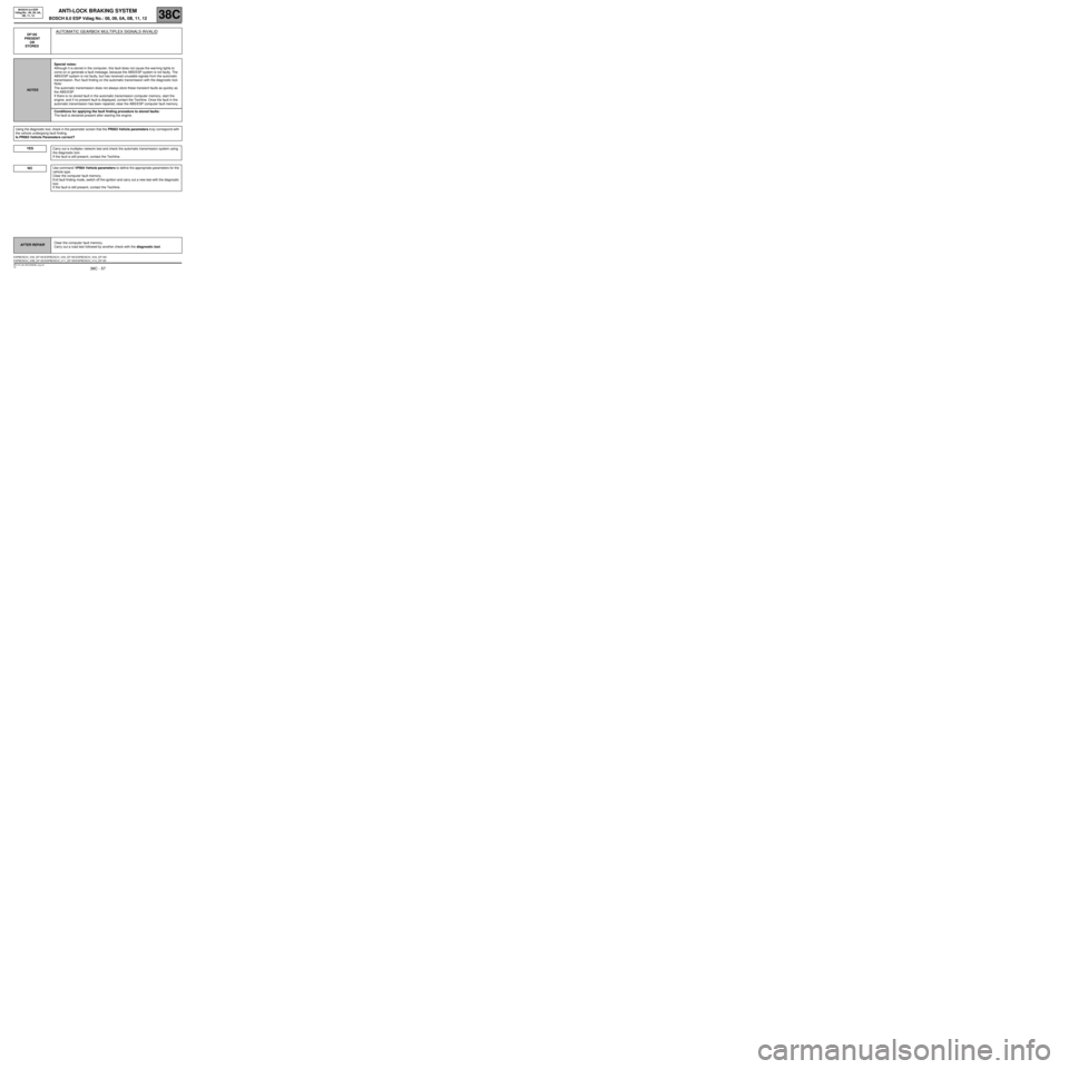
STOREDAUTOMATIC GEARBOX MULTIPLEX SIGNALS INVALID
NOTESSpecial notes:
Although it is stored in the computer, this fault does not cause the warning lights to
come on or generate a fault message, because the ABS/ESP system is not faulty. The
ABS/ESP system is not faulty, but has received unusable signals from the automatic
transmission. Run fault finding on the automatic transmission with the diagnostic tool.
Note:
The automatic transmission does not always store these transient faults as quickly as
the ABS/ESP.
If there is no stored fault in the automatic transmission computer memory, start the
engine, and if no present fault is displayed, contact the Techline. Once the fault in the
automatic transmission has been repaired, clear the ABS/ESP computer fault memory.
Conditions for applying the fault finding procedure to stored faults:
The fault is declared present after starting the engine.
Using the diagnostic tool, check in the parameter screen that the PR063 Vehicle parameters truly correspond with
the vehicle undergoing fault finding.
Is PR063 Vehicle Parameters correct?
YES
Carry out a multiplex network test and check the automatic transmission system using
the diagnostic tool.
If the fault is still present, contact the Techline.
Use command VP004 Vehicle parameters to define the appropriate parameters for the
vehicle type.
Clear the computer fault memory.
Exit fault finding mode, switch off the ignition and carry out a new test with the diagnostic
tool.
If the fault is still present, contact the Techline.
AFTER REPAIRClear the computer fault memory.
Carry out a road test followed by another check with the diagnostic tool.
ESPBOSCH_V08_DF195 /ESPBOSCH_V09_DF195/ESPBOSCH_V0A_DF195/
ESPBOSCH_V0B_DF195 /ESPBOSCH_V11_DF195/ESPBOSCH_V12_DF195