alternator RENAULT SCENIC 2010 J95 / 3.G Engine Compartment Connection Unit Workshop Manual
[x] Cancel search | Manufacturer: RENAULT, Model Year: 2010, Model line: SCENIC, Model: RENAULT SCENIC 2010 J95 / 3.GPages: 56
Page 7 of 56
87G - 7
ENGINE COMPARTMENT CONNECTION UNIT
Fault finding - System operation
87G
V6 MR-372-J84-87G000$132_eng.mif
UPC
Vdiag No.: 44ENGINE COMPARTMENT CONNECTION UNIT
Fault finding - System operation
1. GENERAL FUNCTIONING
The UPC particpates in the following functions:
–distributing and protecting the electrical power,
–keyless vehicles,
–wipers,
–lighting,
–de-icing,
–air conditioning,
–oil pressure detection.
Distributing and protecting electrical power
The main function of the UPC is to switch on and distribute part of the power in order to supply the vehicle systems,
actuators or computers.
Another part of the power supply distribution is housed in the Engine Interconnection Unit but is not controlled
electronically by the computer.
+12 V battery feed
The UPC receives energy from the battery via the 1 track screwed connector and redistributes +12 V around the
vehicle.
+ after ignition feed
The UCH requests the + APC via the multiplex network. When the UPC receives this request, it controls the APC
relay unconditionally.
Energy management
The computer transmits the signal to load the alternator on the multiplex network.
Keyless vehicle
In the Keyless vehicle function, the UPC participates in the start-up sub-function. The computer:
–receives the request to start up the UCH via the multiplex network,
–check that the start-up conditions have been met then controls the starter relay,
–can inhibit or turn off the starter relay command by means of a forbid start-up signal transmitted by the
injection computer on the multiplex network.
Air conditioning
For the operation of this function and the role of the UPC in setting up this function (see 62A, Air conditioning,
Function architecture and General functioning mode).
Cold loop
The computer receives the compressor switch-on request from the injection via the multiplex network.
The computer controls the compressor clutch activation relay.
Heating
The computer also controls the de-icing of the rear tailgate window and the electric rear view mirrors.
Fan assembly
When prompted for the engine check request, the UPC supplies the GMV with power.
MR-372-J84-87G000$132_eng.mif
Page 10 of 56

87G - 10
ENGINE COMPARTMENT CONNECTION UNIT
Fault finding - Replacing components
87G
V6 MR-372-J84-87G000$264_eng.mif
UPC
Vdiag No.: 44ENGINE COMPARTMENT CONNECTION UNIT
Fault finding - Replacing components
1. REPLACING THE COMPUTER
See Workshop repair Manual 364 Mechanics, 87G, Engine interconnection unit (Mégane) or Workshop
Repair Manual 370 Mechanics, 87G, Engine interconnection unit (Scénic).
After replacing:
●Configure the alternator type using command CF001 Alternator type (see Configurations and programming).
●Enter the vehicle VIN using command VP003 Enter VIN.
MR-372-J84-87G000$264_eng.mif
Page 11 of 56
87G - 11
ENGINE COMPARTMENT CONNECTION UNIT
Fault finding - Configurations and programming87G
V6 MR-372-J84-87G000$330_eng.mif
UPC
Vdiag No.: 44ENGINE COMPARTMENT CONNECTION UNIT
Fault finding - Configurations and programming
NOTESIgnition on, engine off.
No. ConfigurationRelated
configuration
readingNote:
CF001ALTERNATOR TYPE:
TG11 110 VALEO
SG12 VALEO
LIE8 150 BOSCH
SG15L VALEO
MELCO 8GMLC001Find out which type of
alternator is fitted on the
vehicle then confirm.
(MELCO = Mitsubishi
Electronics Corporation)
No. Different settings Note:
VP003 ENTERING THE VIN:Find out what the vehicle VIN is then confirm.
MR-372-J84-87G000$330_eng.mif
Page 18 of 56
87G - 18
ENGINE COMPARTMENT CONNECTION UNIT
Fault finding - Conformity check
87G
V6 MR-372-J84-87G000$528_eng.mif
UPC
Vdiag No.: 44
AIR CONDITIONING: Heating
AIR CONDITIONING: Cold loop
NOTESOnly check conformity after a complete check using the diagnostic tool.
Test conditions: Engine stopped, ignition on.
Order FunctionParameter or Status
checked or Action Display and notes Fault finding
1StartingPR010:AlternatorIn %
The value must be
fixed and greater than
98%
Refer to the relevant fault
finding procedure in the
event of a fault.
AC011:Rear
windscreen
de-icingThe rear window
heating resistors and
the door mirrors (if the
vehicle is fitted with
heated door mirrors)
must be supplied with
power and heated.
Order FunctionParameter or Status
checked or Action Display and notes Fault finding
1Fan assemblyAC009:Low speed fan
unitIt must be possible to
hear the fan running at
low speed.
Refer to the relevant fault
finding procedure in the
event of a fault. AC010:High speed fan
unitIt must be possible to
hear the fan running at
high speed
This command cannot
be used on vehicles
not fitted with climate
control
2Air conditioningAC008:Compressor
commandThe compressor clutch
must be heard (the
compressor command
is not permitted when
the engine is running)
Page 23 of 56
87G - 23
ENGINE COMPARTMENT CONNECTION UNIT
Fault finding - Conformity check
87G
V6 MR-372-J84-87G000$528_eng.mif
UPC
Vdiag No.: 44
AIR CONDITIONING: Heating
AIR CONDITIONING: Cold loop
NOTESOnly check conformity after a complete check using the diagnostic tool.
Condition for carrying out the operation: the engine must be running.
Order FunctionParameter or Status
checked or Action Display and notes Fault finding
1StartingPR010:AlternatorIn %
The value varies
according to electricity
consumption.
Refer to the relevant fault
finding method in the event
of a fault.
AC011:Rear
windscreen de-
icingThe heating resistance
for the rear window
and the door mirrors
(if the vehicle is fitted
with door mirrors) must
be supplied with power
and supply heat
Order FunctionParameter or Status
checked or Action Display and notes Fault finding
1Fan assemblyAC009:Low speed fan
unitThe fan must be heard
running at low speed
Refer to the relevant fault
finding procedure in the
event of a fault. AC010:High speed fan
unitThe fan must be heard
running at a high
speed
This command cannot
be used on vehicles
which are not fitted
with climate control
2Air conditioningAC008:Compressor
control(this command is not
permitted when the
engine is running)
Page 26 of 56
87G - 26
ENGINE COMPARTMENT CONNECTION UNIT
Fault finding - Status and parameter summary table87G
V6 MR-372-J84-87G000$594_eng.mif
UPC
Vdiag No.: 44ENGINE COMPARTMENT CONNECTION UNIT
Fault finding - Status and parameter summary table
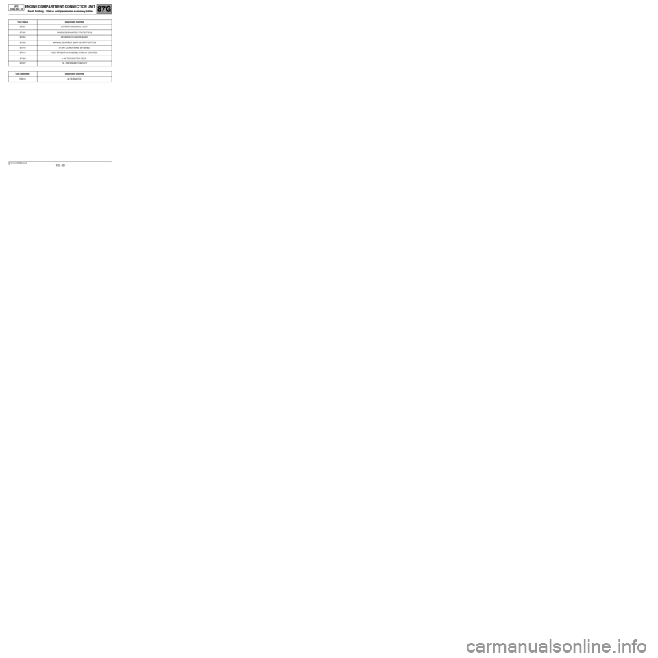
Tool status Diagnostic tool title
ET001 BATTERY WARNING LIGHT
ET002 WINDSCREEN WIPER PROTECTION
ET004 REVERSE GEAR ENGAGED
ET005 MANUAL GEARBOX GEAR LEVER POSITION
ET010 START CONDITIONS SATISFIED
ET013 HIGH SPEED FAN ASSEMBLY RELAY CONTROL
ET026 + AFTER IGNITION FEED
ET027 OIL PRESSURE CONTACT
Tool parameter Diagnostic tool title
PR010 ALTERNATOR
MR-372-J84-87G000$594_eng.mif
Page 27 of 56
87G - 27
ENGINE COMPARTMENT CONNECTION UNIT
Fault finding - Interpretation of statuses
87G
V6 MR-372-J84-87G000$660_eng.mif
UPC
Vdiag No.: 44ENGINE COMPARTMENT CONNECTION UNIT
Fault finding - Interpretation of statuses
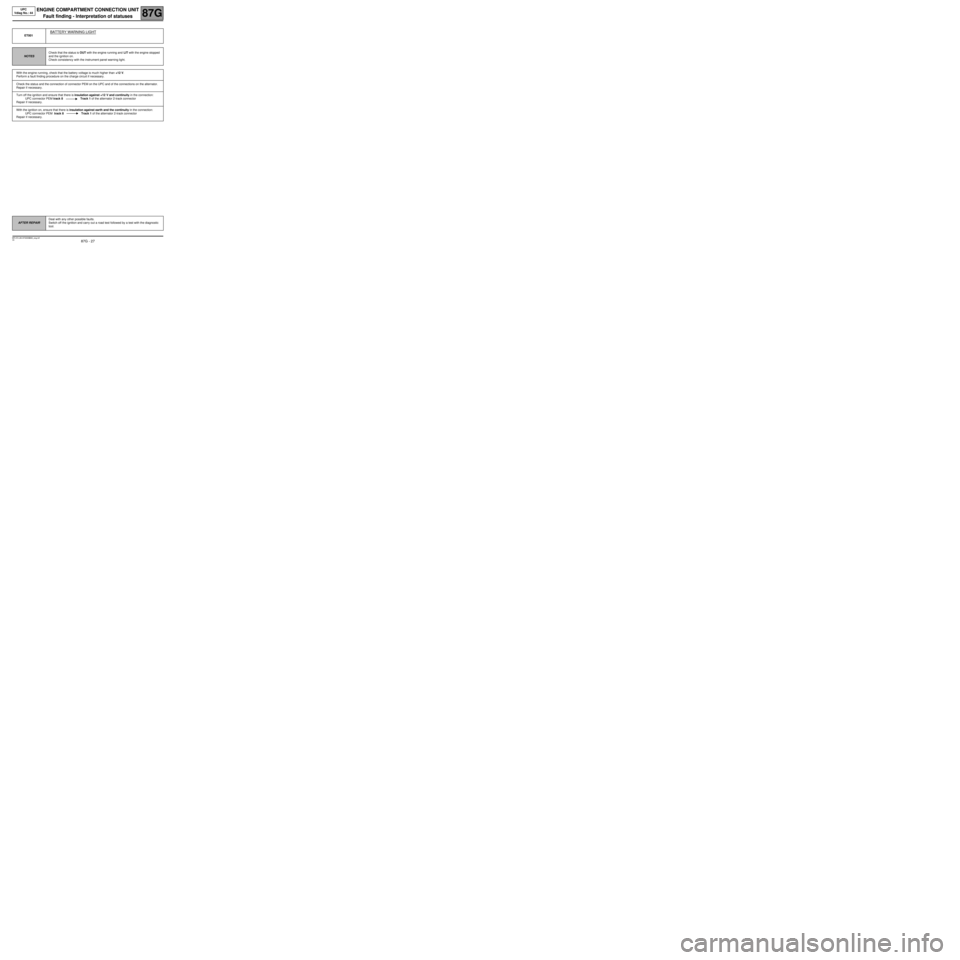
ET001
BATTERY WARNING LIGHT
NOTESCheck that the status is OUT with the engine running and LIT with the engine stopped
and the ignition on.
Check consistency with the instrument panel warning light.
With the engine running, check that the battery voltage is much higher than +12 V.
Perform a fault finding procedure on the charge circuit if necessary.
Check the status and the connection of connector PEM on the UPC and of the connections on the alternator.
Repair if necessary.
Turn off the ignition and ensure that there is insulation against +12 V and continuity in the connection:
UPC connector PEM track 8 Track 1 of the alternator 2-track connector
Repair if necessary.
With the ignition on, ensure that there is insulation against earth and the continuity in the connection:
UPC connector PEM track 8 Track 1 of the alternator 2-track connector
Repair if necessary.
AFTER REPAIRDeal with any other possible faults.
Switch off the ignition and carry out a road test followed by a test with the diagnostic
tool.
MR-372-J84-87G000$660_eng.mif
Page 35 of 56
87G - 35
ENGINE COMPARTMENT CONNECTION UNIT
87G
V6 MR-372-J84-87G000$726_eng.mif
UPC
Vdiag No.: 44
Fault finding - Interpretation of parameters
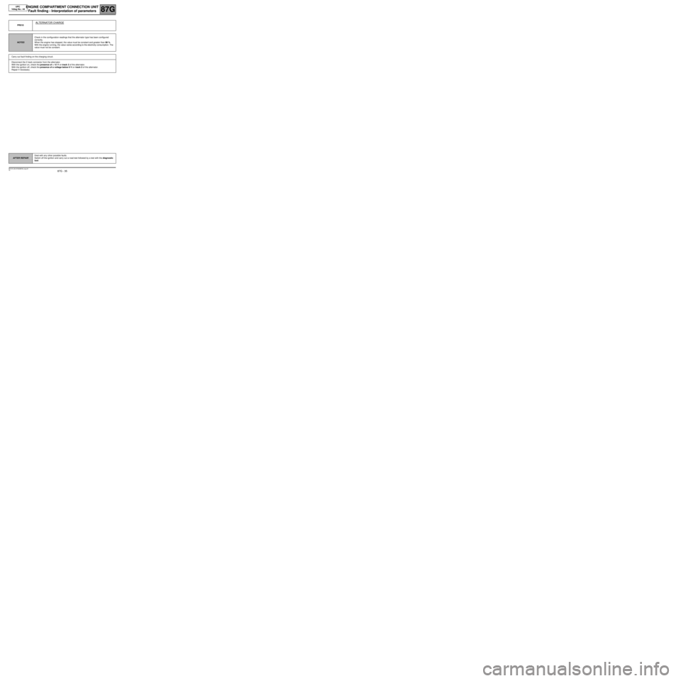
PR010
ALTERNATOR CHARGE
NOTESCheck in the configuration readings that the alternator type has been configured
correctly.
When the engine has stopped, the value must be constant and greater than 98 %.
With the engine running, the value varies according to the electricity consumption. The
value must not be constant.
Carry out fault finding on the charging circuit.
Disconnect the 2 track connector from the alternator.
With the ignition on, check the presence of + 12 V on track 2 of the alternator.
With the ignition off, check the presence of a voltage below 6 V on track 2 of the alternator.
Repair if necessary.
AFTER REPAIRDeal with any other possible faults.
Switch off the ignition and carry out a road test followed by a test with the diagnostic
tool.
MR-372-J84-87G000$726_eng.mif