light RENAULT SCENIC 2010 J95 / 3.G Engine Compartment Connection Unit Workshop Manual
[x] Cancel search | Manufacturer: RENAULT, Model Year: 2010, Model line: SCENIC, Model: RENAULT SCENIC 2010 J95 / 3.GPages: 56
Page 2 of 56
87G - 2
ENGINE COMPARTMENT CONNECTION UNIT
Fault finding - Introduction
87G
V6 MR-372-J84-87G000$066_eng.mif
187G
UPC
Vdiag No.: 44ENGINE COMPARTMENT CONNECTION UNIT
Fault finding - Introduction
1. SCOPE OF THIS DOCUMENT
This document presents the fault finding procedure applicable to all computers with the following specifications:
2. PREREQUISITES FOR FAULT FINDING
Documentation type
Fault finding procedures (this manual):
–Assisted fault finding (integrated into the diagnostic tool), Dialogys.
Wiring diagrams:
–Visu-Schéma (CD-ROM), paper version.
Type of diagnostic tools
–CLIP
Special tooling required
3. RECAP
Procedure
To run diagnostics on the vehicle's computers, switch on the ignition in fault finding mode (forced + after ignition
feed).
Proceed as follows:
–insert the vehicle card in the card reader,
–press and hold Start button (longer than 5 seconds) with start conditions not fulfilled,
–connect the diagnostic tool and perform the desired operations.
To turn off the + APC feed proceed as follows:
–disconnect the diagnostic tool,
–press the Start button twice briefly (less than 3 seconds),
–check that the + APC has been turned off by the computer indicator lights on the instrument panel
being switched off. Vehicle(s): MEGANE II, SCENIC II
Function concerned: UPCName of computer: UPC
VDIAG No.: 44
Special tooling required
Multimeter
Universal bornier
Note:
The left-hand and right-hand xenon lamp computers are powered when the dipped beam headlights light up. It will
therefore not be possible to run fault finding on them until the ignition has been switched on in fault finding mode
(forced + APC) and the dipped beam headlights have been switched on.
MR-372-J84-87G000$066_eng.mif
Page 5 of 56
87G - 5
ENGINE COMPARTMENT CONNECTION UNIT
Fault finding - Introduction
87G
V6 MR-372-J84-87G000$066_eng.mif
UPC
Vdiag No.: 44
Wiring check:
Fault finding problems:
Disconnecting the connectors and/or manipulating the wiring harness may temporarily remove the cause of a fault.
Electrical measurements of voltage, resistance and insulation are generally correct, especially if the fault is not
present when the analysis is made (stored fault).
Visual inspection:
Look for damage under the bonnet and in the passenger compartment.
Carefully check the protective parts, insulators and wiring harness routing.
Look for signs of oxidation.
Tactile inspection:
While manipulating the wiring harness, use the diagnostic tool to note any change in fault status from stored to
present.
Make sure that the connectors are properly tightened,
Apply light pressure to the connectors,
Twist the wiring harness.
If there is a change in status, try to locate the source of the fault.
Inspection of each component:
Disconnect the connectors and check the appearance of the clips and tabs, as well as their crimping (no crimping on
the insulating section).
Make sure that the clips and tabs are properly locked in the sockets.
Check that no clips or tabs have been dislodged during connection.
Check the clip contact pressure using an appropriate model of tab.
Resistance check:
Check the continuity of entire lines, then section by section.
Look for a short circuit to earth, the +12 V feed or with another wire.
If a fault is detected, repair or replace the wiring harness.
Page 7 of 56
87G - 7
ENGINE COMPARTMENT CONNECTION UNIT
Fault finding - System operation
87G
V6 MR-372-J84-87G000$132_eng.mif
UPC
Vdiag No.: 44ENGINE COMPARTMENT CONNECTION UNIT
Fault finding - System operation
1. GENERAL FUNCTIONING
The UPC particpates in the following functions:
–distributing and protecting the electrical power,
–keyless vehicles,
–wipers,
–lighting,
–de-icing,
–air conditioning,
–oil pressure detection.
Distributing and protecting electrical power
The main function of the UPC is to switch on and distribute part of the power in order to supply the vehicle systems,
actuators or computers.
Another part of the power supply distribution is housed in the Engine Interconnection Unit but is not controlled
electronically by the computer.
+12 V battery feed
The UPC receives energy from the battery via the 1 track screwed connector and redistributes +12 V around the
vehicle.
+ after ignition feed
The UCH requests the + APC via the multiplex network. When the UPC receives this request, it controls the APC
relay unconditionally.
Energy management
The computer transmits the signal to load the alternator on the multiplex network.
Keyless vehicle
In the Keyless vehicle function, the UPC participates in the start-up sub-function. The computer:
–receives the request to start up the UCH via the multiplex network,
–check that the start-up conditions have been met then controls the starter relay,
–can inhibit or turn off the starter relay command by means of a forbid start-up signal transmitted by the
injection computer on the multiplex network.
Air conditioning
For the operation of this function and the role of the UPC in setting up this function (see 62A, Air conditioning,
Function architecture and General functioning mode).
Cold loop
The computer receives the compressor switch-on request from the injection via the multiplex network.
The computer controls the compressor clutch activation relay.
Heating
The computer also controls the de-icing of the rear tailgate window and the electric rear view mirrors.
Fan assembly
When prompted for the engine check request, the UPC supplies the GMV with power.
MR-372-J84-87G000$132_eng.mif
Page 8 of 56
87G - 8
ENGINE COMPARTMENT CONNECTION UNIT
Fault finding - System operation
87G
V6 MR-372-J84-87G000$132_eng.mif
UPC
Vdiag No.: 44
Front wipers
The UPC receives the wiping requests from the UCH via the multiplex network.
The computer then controls the following requests:
–low or high speed windscreen wiper,
–windscreen wiper park position.
Lights
The UPC receives the lighting requests from the UCH via the multiplex network.
The computer then controls the following requests:
–side lights,
–dipped beam headlights,
–main beam headlights,
–front fog light.
Detecting the oil pressure
The UPC receives the signal from the oil pressure sensor and makes it available on the multiplex network.
2. UPC LEVELS
3 UPC levels can be fitted on vehicles:
–Entry level UPC,
–Top of the range UPC N2,
–Top of the range UPC N3.
Only the top of the range N2 and N3 UPCs are available as spare parts.
The N2 and N3 versions can be distinguished in the extent to which they control the high speed blower:
–on the N2, the UPC controls an external relay,
–on N3, the relay is integrated into the UPC.
Page 16 of 56
87G - 16
ENGINE COMPARTMENT CONNECTION UNIT
Fault finding - Conformity check
87G
V6 MR-372-J84-87G000$528_eng.mif
UPC
Vdiag No.: 44ENGINE COMPARTMENT CONNECTION UNIT
Fault finding - Conformity check
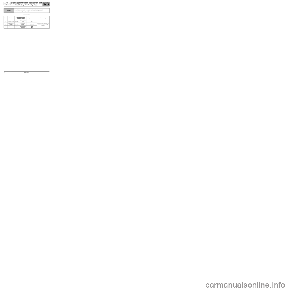
MAIN SCREEN
NOTESOnly check conformity after a complete check using the diagnostic tool.
Test conditions: Engine stopped, ignition on.
Order FunctionParameter or Status
checked or Action Display and notes Fault finding
1Charging circuitET001:Battery warning
lightLIT
In the event of a fault, refer to
the relevant fault finding
method. 2Oil pressure
contactET027:Oil pressure
contactCLOSED
3GearboxET004:Reverse gear
engagedYES
NO
MR-372-J84-87G000$528_eng.mif
Page 20 of 56
87G - 20
ENGINE COMPARTMENT CONNECTION UNIT
Fault finding - Conformity check
87G
V6 MR-372-J84-87G000$528_eng.mif
UPC
Vdiag No.: 44
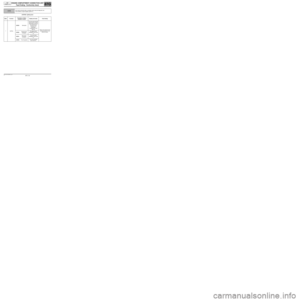
LIGHTING: Lighting power
NOTESOnly check conformity after a complete check using the diagnostic tool.
Test conditions: Engine stopped, ignition on.
Order FunctionParameter or Status
checked or Action Display and notes Fault finding
1LightingAC003:Side lightsThe front and rear side
lights and the number
plate lights as well as
the controls and
switches in the
passenger
compartment must
light up.
Refer to the relevant fault
finding procedure in the
event of a fault.
AC002:Dipped beam
headlightsThe dipped beam
headlights must come
on.
AC001:Main beam
headlightsThe main beam
headlights must come
on.
AC004:Front fog lightsThe front fog lights
must come on.
Page 21 of 56
87G - 21
ENGINE COMPARTMENT CONNECTION UNIT
Fault finding - Conformity check
87G
V6 MR-372-J84-87G000$528_eng.mif
UPC
Vdiag No.: 44
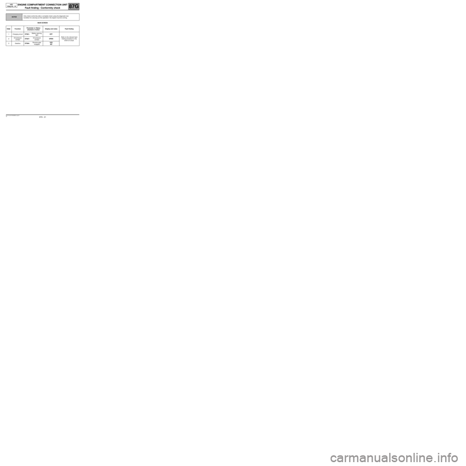
MAIN SCREEN
NOTESOnly check conformity after a complete check using the diagnostic tool.
Condition for carrying out this operation: the engine must be running.
Order FunctionParameter or Status
checked or Action Display and notes Fault finding
1Charging circuitET001:Battery warning
lightOFF
Refer to the relevant fault
finding procedure in the
event of a fault. 2Oil pressure
contactET027:Oil pressure
contactOPEN
3GearboxET004:Reverse gear
engagedYES
NO
Page 25 of 56

87G - 25
ENGINE COMPARTMENT CONNECTION UNIT
Fault finding - Conformity check
87G
V6 MR-372-J84-87G000$528_eng.mif
UPC
Vdiag No.: 44
LIGHTING: Lighting power
NOTESOnly check conformity after a complete check using the diagnostic tool.
Condition for carrying out the operation: the engine must be running.
Order FunctionParameter or Status
checked or Action Display and notes Fault finding
1LightingAC003:Side lightsThe front and rear side
lights and the number
plate lights as well as
the controls and
switches inside the
passenger
compartment must
light up.
Refer to the relevant fault
finding procedure in the
event of a fault.
AC002:Dipped beam
headlightsThe dipped beam
headlights must come
on.
AC001:Main beam
headlightsThe main beam
headlights must come
on.
AC004:Front fog lightsThe front fog lights
must come on.
Page 26 of 56
87G - 26
ENGINE COMPARTMENT CONNECTION UNIT
Fault finding - Status and parameter summary table87G
V6 MR-372-J84-87G000$594_eng.mif
UPC
Vdiag No.: 44ENGINE COMPARTMENT CONNECTION UNIT
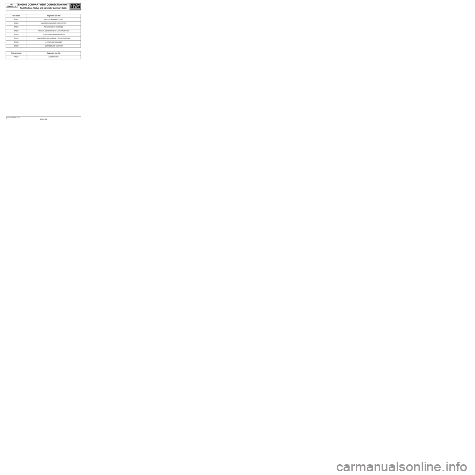
Fault finding - Status and parameter summary table
Tool status Diagnostic tool title
ET001 BATTERY WARNING LIGHT
ET002 WINDSCREEN WIPER PROTECTION
ET004 REVERSE GEAR ENGAGED
ET005 MANUAL GEARBOX GEAR LEVER POSITION
ET010 START CONDITIONS SATISFIED
ET013 HIGH SPEED FAN ASSEMBLY RELAY CONTROL
ET026 + AFTER IGNITION FEED
ET027 OIL PRESSURE CONTACT
Tool parameter Diagnostic tool title
PR010 ALTERNATOR
MR-372-J84-87G000$594_eng.mif
Page 27 of 56
87G - 27
ENGINE COMPARTMENT CONNECTION UNIT
Fault finding - Interpretation of statuses
87G
V6 MR-372-J84-87G000$660_eng.mif
UPC
Vdiag No.: 44ENGINE COMPARTMENT CONNECTION UNIT
Fault finding - Interpretation of statuses
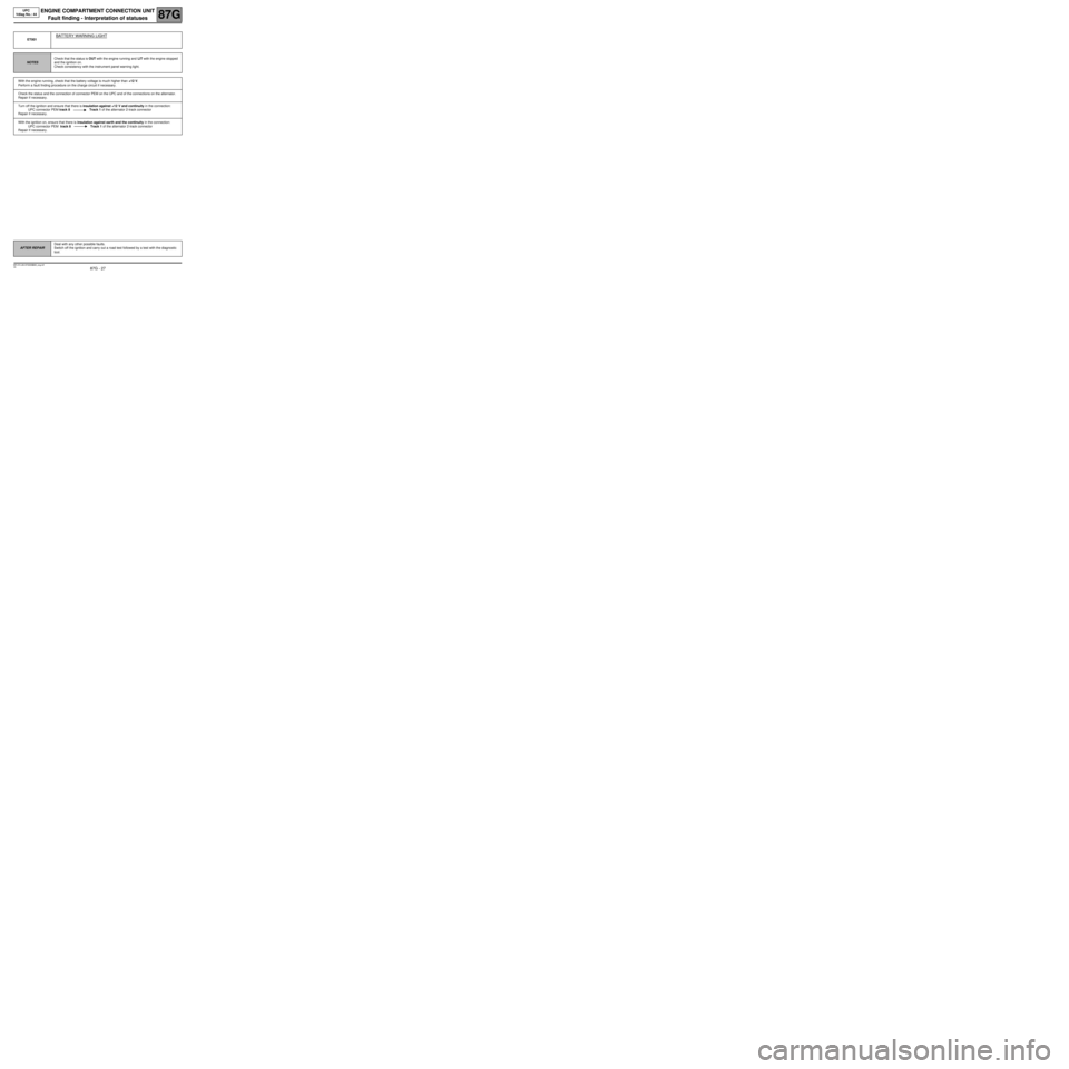
ET001
BATTERY WARNING LIGHT
NOTESCheck that the status is OUT with the engine running and LIT with the engine stopped
and the ignition on.
Check consistency with the instrument panel warning light.
With the engine running, check that the battery voltage is much higher than +12 V.
Perform a fault finding procedure on the charge circuit if necessary.
Check the status and the connection of connector PEM on the UPC and of the connections on the alternator.
Repair if necessary.
Turn off the ignition and ensure that there is insulation against +12 V and continuity in the connection:
UPC connector PEM track 8 Track 1 of the alternator 2-track connector
Repair if necessary.
With the ignition on, ensure that there is insulation against earth and the continuity in the connection:
UPC connector PEM track 8 Track 1 of the alternator 2-track connector
Repair if necessary.
AFTER REPAIRDeal with any other possible faults.
Switch off the ignition and carry out a road test followed by a test with the diagnostic
tool.
MR-372-J84-87G000$660_eng.mif