charging RENAULT SCENIC 2011 J95 / 3.G Engine And Peripherals EDC16 Owner's Manual
[x] Cancel search | Manufacturer: RENAULT, Model Year: 2011, Model line: SCENIC, Model: RENAULT SCENIC 2011 J95 / 3.GPages: 365, PDF Size: 2.11 MB
Page 90 of 365
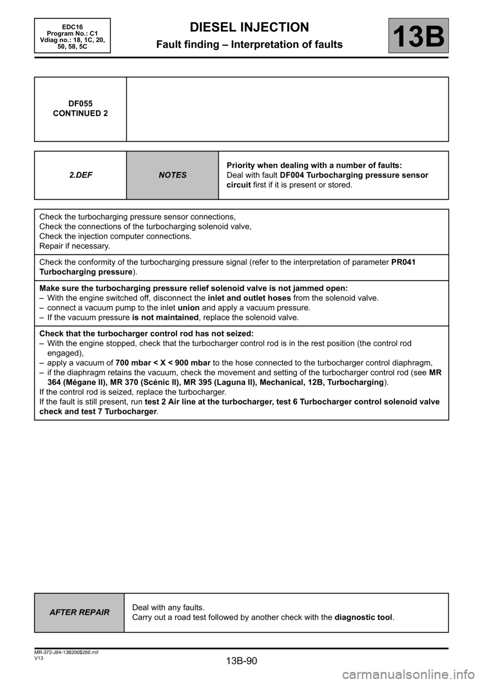
13B-90
MR-372-J84-13B200$288.mif
V13
DIESEL INJECTION
Fault finding – Interpretation of faults
EDC16
Program No.: C1
Vdiag no.: 18, 1C, 20,
50, 58, 5C
13B
DF055
CONTINUED 2
2.DEF
NOTESPriority when dealing with a number of faults:
Deal with fault DF004 Turbocharging pressure sensor
circuit first if it is present or stored.
Check the turbocharging pressure sensor connections,
Check the connections of the turbocharging solenoid valve,
Check the injection computer connections.
Repair if necessary.
Check the conformity of the turbocharging pressure signal (refer to the interpretation of parameter PR041
Turbocharging pressure).
Make sure the turbocharging pressure relief solenoid valve is not jammed open:
– With the engine switched off, disconnect the inlet and outlet hoses from the solenoid valve.
– connect a vacuum pump to the inlet union and apply a vacuum pressure.
– If the vacuum pressure is not maintained, replace the solenoid valve.
Check that the turbocharger control rod has not seized:
– With the engine stopped, check that the turbocharger control rod is in the rest position (the control rod
engaged),
– apply a vacuum of 700 mbar < X < 900 mbar to the hose connected to the turbocharger control diaphragm,
– if the diaphragm retains the vacuum, check the movement and setting of the turbocharger control rod (see MR
364 (Mégane II), MR 370 (Scénic II), MR 395 (Laguna II), Mechanical, 12B, Turbocharging).
If the control rod is seized, replace the turbocharger.
If the fault is still present, run test 2 Air line at the turbocharger, test 6 Turbocharger control solenoid valve
check and test 7 Turbocharger.
AFTER REPAIRDeal with any faults.
Carry out a road test followed by another check with the diagnostic tool.
Page 132 of 365
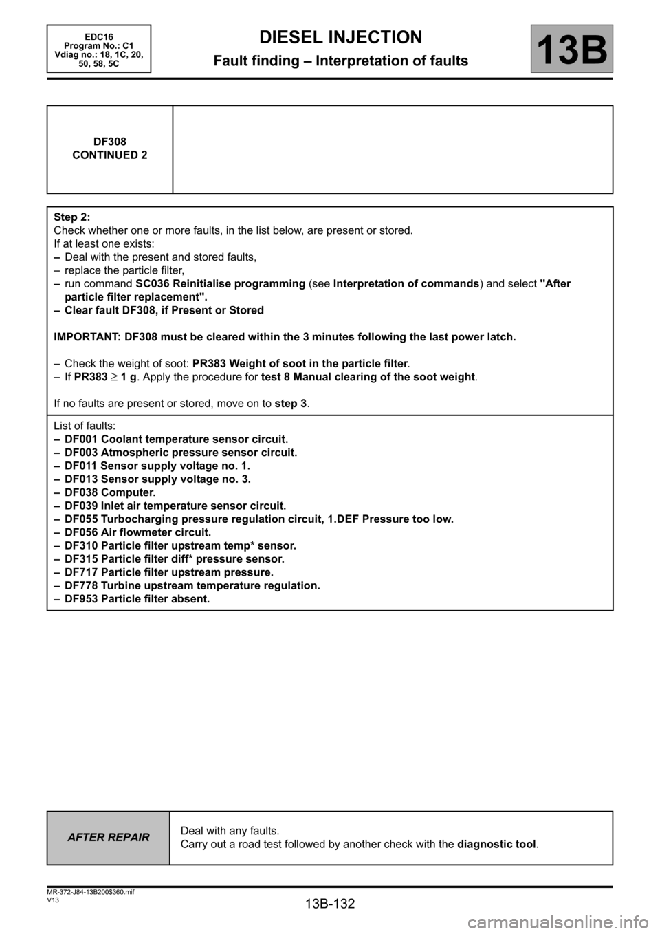
13B-132
MR-372-J84-13B200$360.mif
V13
DIESEL INJECTION
Fault finding – Interpretation of faults
EDC16
Program No.: C1
Vdiag no.: 18, 1C, 20,
50, 58, 5C
13B
DF308
CONTINUED 2
Step 2:
Check whether one or more faults, in the list below, are present or stored.
If at least one exists:
–Deal with the present and stored faults,
– replace the particle filter,
–run command SC036 Reinitialise programming (see Interpretation of commands) and select "After
particle filter replacement".
– Clear fault DF308, if Present or Stored
IMPORTANT: DF308 must be cleared within the 3 minutes following the last power latch.
– Check the weight of soot: PR383 Weight of soot in the particle filter.
– If PR383
≥ 1 g. Apply the procedure for test 8 Manual clearing of the soot weight.
If no faults are present or stored, move on to step 3.
List of faults:
– DF001 Coolant temperature sensor circuit.
– DF003 Atmospheric pressure sensor circuit.
– DF011 Sensor supply voltage no. 1.
– DF013 Sensor supply voltage no. 3.
– DF038 Computer.
– DF039 Inlet air temperature sensor circuit.
– DF055 Turbocharging pressure regulation circuit, 1.DEF Pressure too low.
– DF056 Air flowmeter circuit.
– DF310 Particle filter upstream temp* sensor.
– DF315 Particle filter diff* pressure sensor.
– DF717 Particle filter upstream pressure.
– DF778 Turbine upstream temperature regulation.
– DF953 Particle filter absent.
AFTER REPAIRDeal with any faults.
Carry out a road test followed by another check with the diagnostic tool.
Page 149 of 365
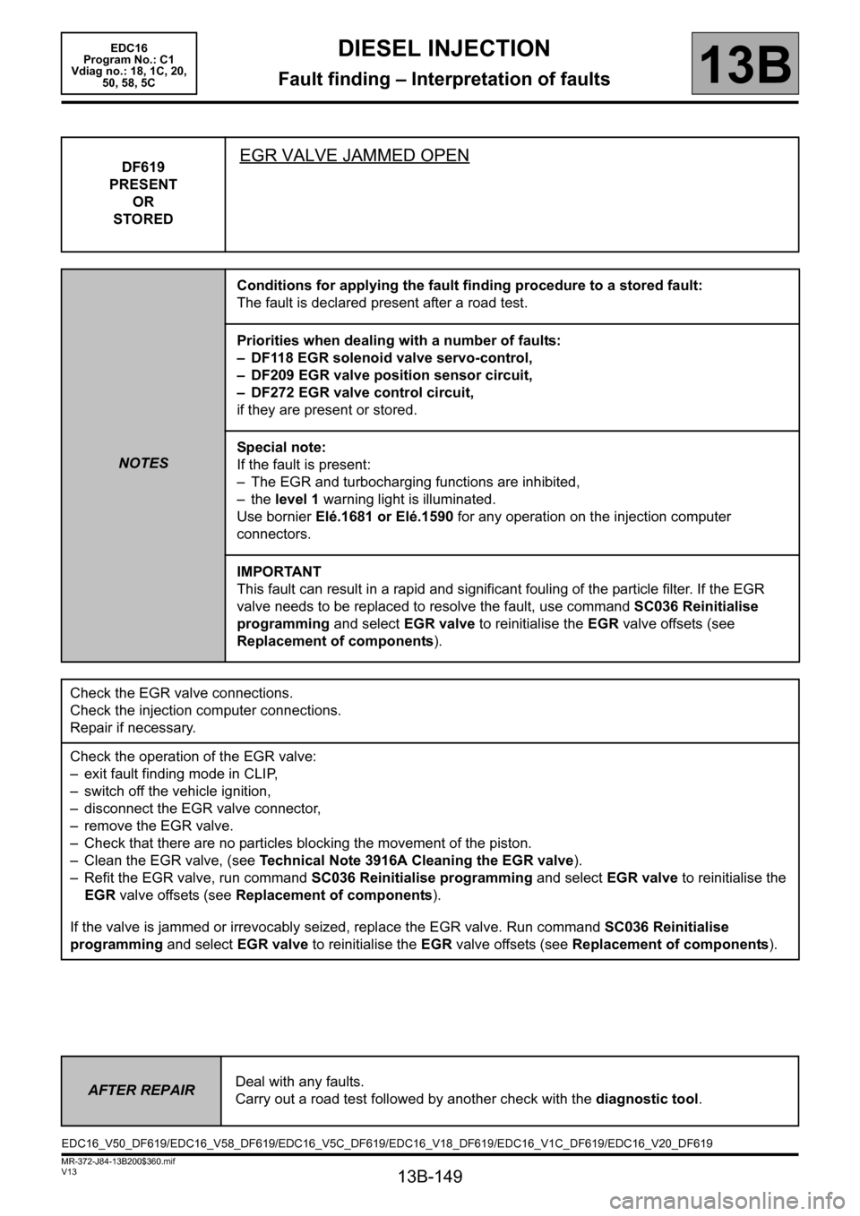
13B-149
MR-372-J84-13B200$360.mif
V13
DIESEL INJECTION
Fault finding – Interpretation of faults
EDC16
Program No.: C1
Vdiag no.: 18, 1C, 20,
50, 58, 5C
13B
DF619
PRESENT
OR
STOREDEGR VALVE JAMMED OPEN
NOTESConditions for applying the fault finding procedure to a stored fault:
The fault is declared present after a road test.
Priorities when dealing with a number of faults:
– DF118 EGR solenoid valve servo-control,
– DF209 EGR valve position sensor circuit,
– DF272 EGR valve control circuit,
if they are present or stored.
Special note:
If the fault is present:
– The EGR and turbocharging functions are inhibited,
– the level 1 warning light is illuminated.
Use bornier Elé.1681 or Elé.1590 for any operation on the injection computer
connectors.
IMPORTANT
This fault can result in a rapid and significant fouling of the particle filter. If the EGR
valve needs to be replaced to resolve the fault, use command SC036 Reinitialise
programming and select EGR valve to reinitialise the EGR valve offsets (see
Replacement of components).
Check the EGR valve connections.
Check the injection computer connections.
Repair if necessary.
Check the operation of the EGR valve:
– exit fault finding mode in CLIP,
– switch off the vehicle ignition,
– disconnect the EGR valve connector,
– remove the EGR valve.
– Check that there are no particles blocking the movement of the piston.
– Clean the EGR valve, (see Technical Note 3916A Cleaning the EGR valve).
– Refit the EGR valve, run command SC036 Reinitialise programming and select EGR valve to reinitialise the
EGR valve offsets (see Replacement of components).
If the valve is jammed or irrevocably seized, replace the EGR valve. Run command SC036 Reinitialise
programming and select EGR valve to reinitialise the EGR valve offsets (see Replacement of components).
AFTER REPAIRDeal with any faults.
Carry out a road test followed by another check with the diagnostic tool.
EDC16_V50_DF619/EDC16_V58_DF619/EDC16_V5C_DF619/EDC16_V18_DF619/EDC16_V1C_DF619/EDC16_V20_DF619
Page 150 of 365
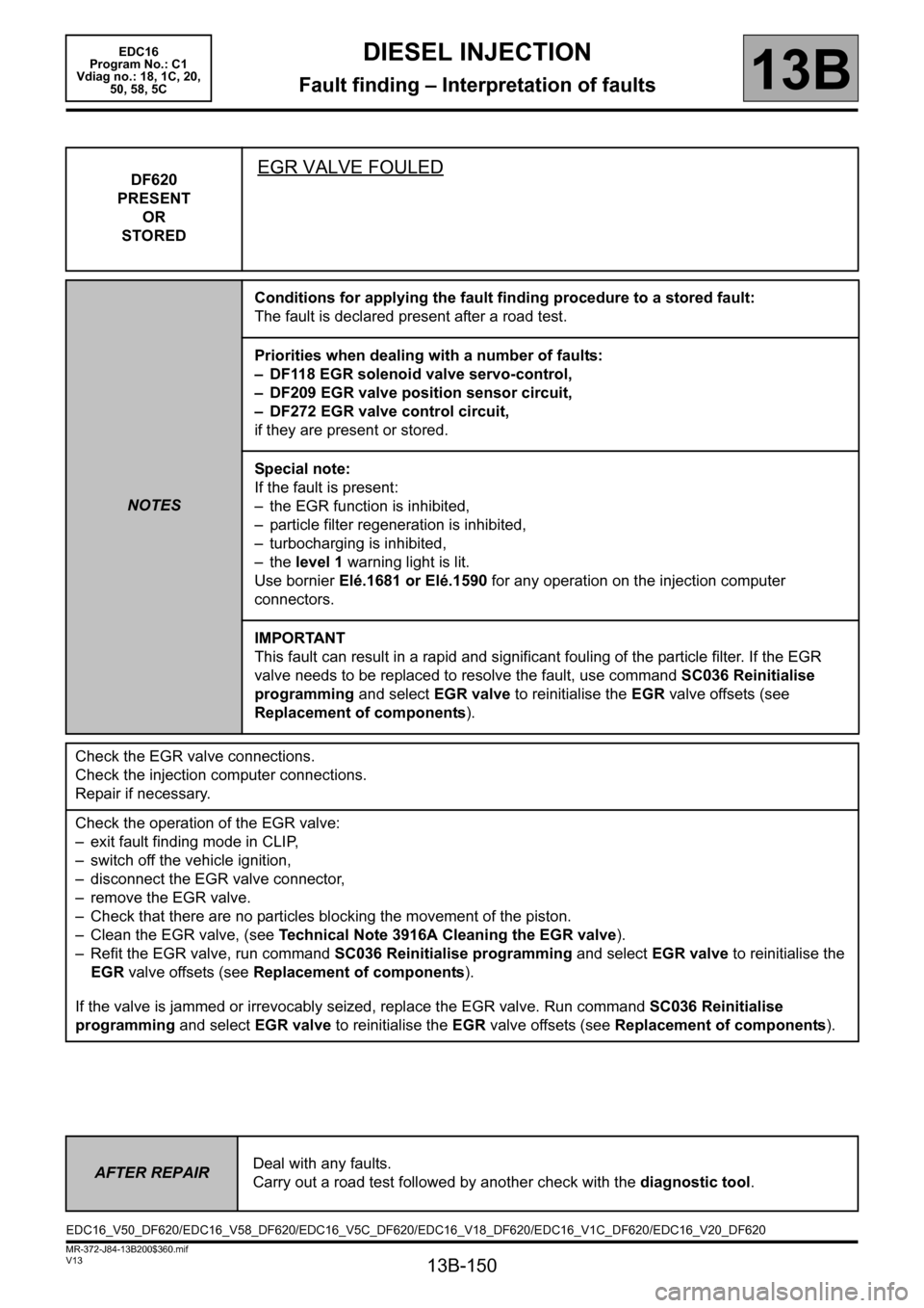
13B-150
MR-372-J84-13B200$360.mif
V13
DIESEL INJECTION
Fault finding – Interpretation of faults
EDC16
Program No.: C1
Vdiag no.: 18, 1C, 20,
50, 58, 5C
13B
DF620
PRESENT
OR
STOREDEGR VALVE FOULED
NOTESConditions for applying the fault finding procedure to a stored fault:
The fault is declared present after a road test.
Priorities when dealing with a number of faults:
– DF118 EGR solenoid valve servo-control,
– DF209 EGR valve position sensor circuit,
– DF272 EGR valve control circuit,
if they are present or stored.
Special note:
If the fault is present:
– the EGR function is inhibited,
– particle filter regeneration is inhibited,
– turbocharging is inhibited,
– the level 1 warning light is lit.
Use bornier Elé.1681 or Elé.1590 for any operation on the injection computer
connectors.
IMPORTANT
This fault can result in a rapid and significant fouling of the particle filter. If the EGR
valve needs to be replaced to resolve the fault, use command SC036 Reinitialise
programming and select EGR valve to reinitialise the EGR valve offsets (see
Replacement of components).
Check the EGR valve connections.
Check the injection computer connections.
Repair if necessary.
Check the operation of the EGR valve:
– exit fault finding mode in CLIP,
– switch off the vehicle ignition,
– disconnect the EGR valve connector,
– remove the EGR valve.
– Check that there are no particles blocking the movement of the piston.
– Clean the EGR valve, (see Technical Note 3916A Cleaning the EGR valve).
– Refit the EGR valve, run command SC036 Reinitialise programming and select EGR valve to reinitialise the
EGR valve offsets (see Replacement of components).
If the valve is jammed or irrevocably seized, replace the EGR valve. Run command SC036 Reinitialise
programming and select EGR valve to reinitialise the EGR valve offsets (see Replacement of components).
AFTER REPAIRDeal with any faults.
Carry out a road test followed by another check with the diagnostic tool.
EDC16_V50_DF620/EDC16_V58_DF620/EDC16_V5C_DF620/EDC16_V18_DF620/EDC16_V1C_DF620/EDC16_V20_DF620
Page 210 of 365
13B-210
MR-372-J84-13B200$576.mif
V13
13B
DIESEL INJECTION
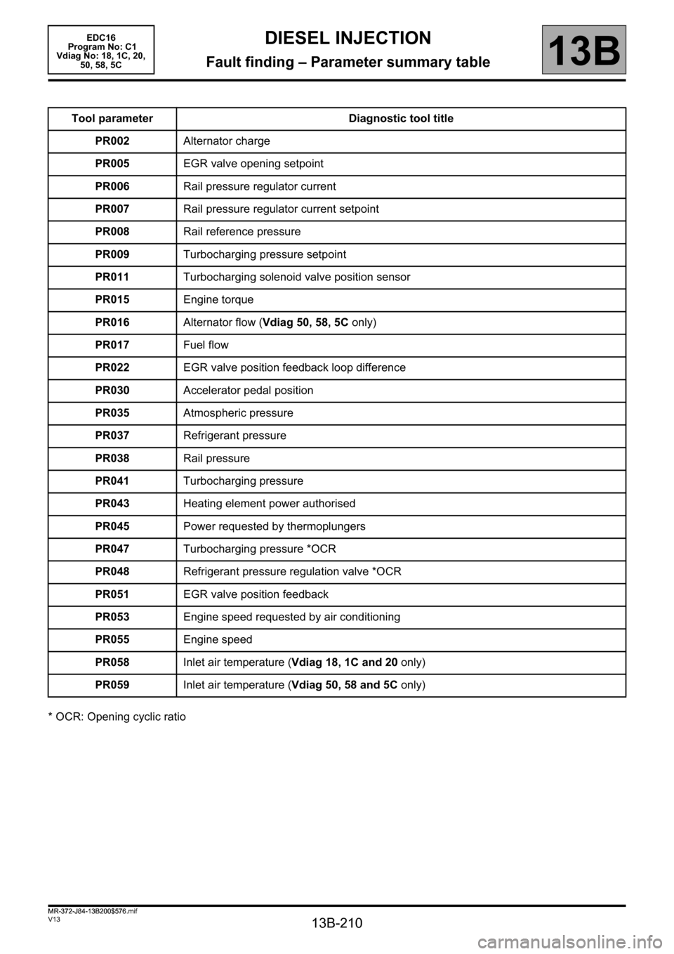
Fault finding – Parameter summary table
* OCR: Opening cyclic ratioTool parameter Diagnostic tool title
PR002Alternator charge
PR005EGR valve opening setpoint
PR006Rail pressure regulator current
PR007Rail pressure regulator current setpoint
PR008Rail reference pressure
PR009Turbocharging pressure setpoint
PR011Turbocharging solenoid valve position sensor
PR015Engine torque
PR016Alternator flow (Vdiag 50, 58, 5C only)
PR017Fuel flow
PR022EGR valve position feedback loop difference
PR030Accelerator pedal position
PR035Atmospheric pressure
PR037Refrigerant pressure
PR038Rail pressure
PR041Turbocharging pressure
PR043Heating element power authorised
PR045Power requested by thermoplungers
PR047Turbocharging pressure *OCR
PR048Refrigerant pressure regulation valve *OCR
PR051EGR valve position feedback
PR053Engine speed requested by air conditioning
PR055Engine speed
PR058Inlet air temperature (Vdiag 18, 1C and 20 only)
PR059Inlet air temperature (Vdiag 50, 58 and 5C only)
MR-372-J84-13B200$576.mif
EDC16
Program No: C1
Vdiag No: 18, 1C, 20,
50, 58, 5C
Page 211 of 365
13B-211
MR-372-J84-13B200$576.mif
V13
DIESEL INJECTION
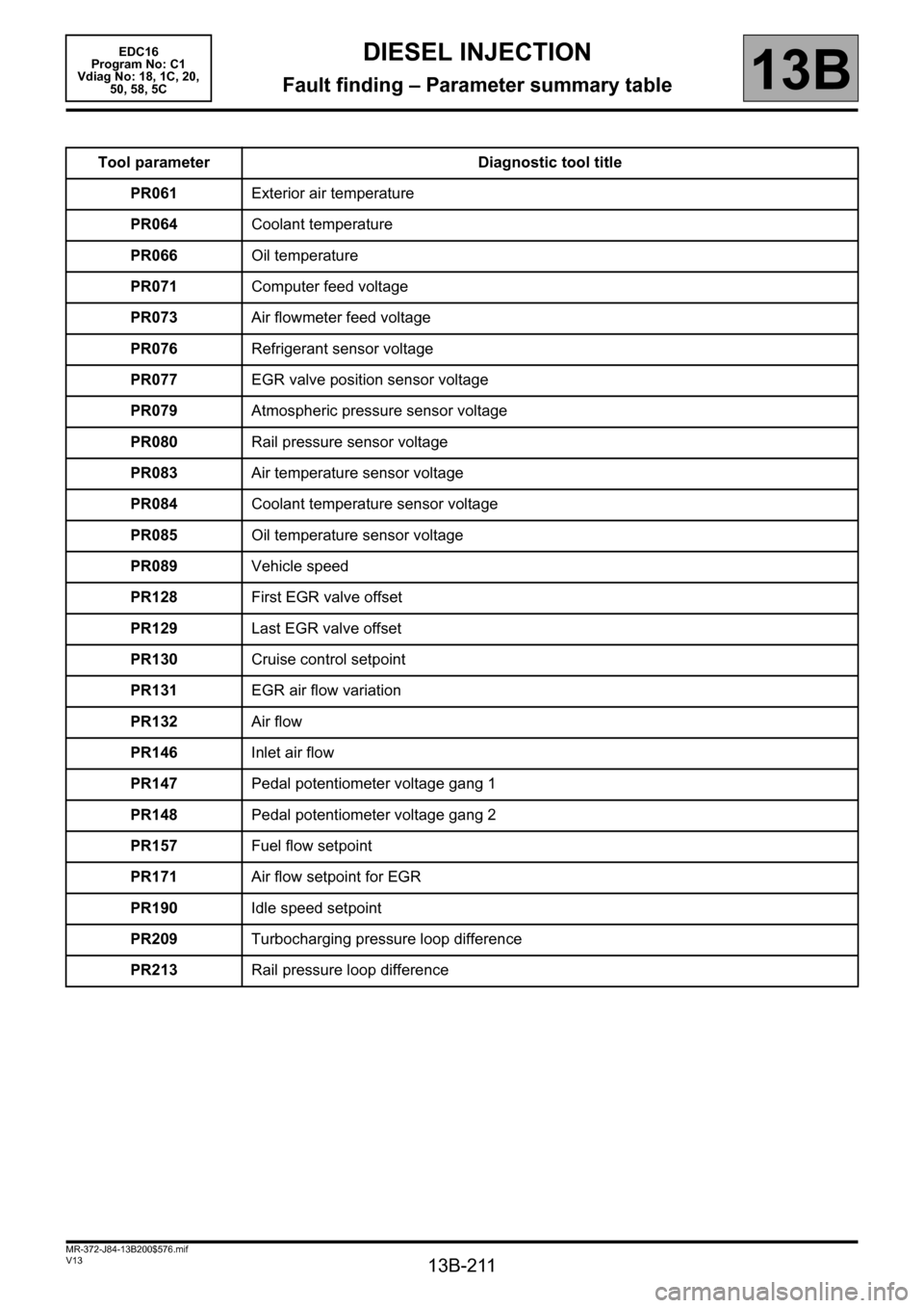
Fault finding – Parameter summary table
EDC16
Program No: C1
Vdiag No: 18, 1C, 20,
50, 58, 5C
13B
Tool parameter Diagnostic tool title
PR061Exterior air temperature
PR064Coolant temperature
PR066Oil temperature
PR071Computer feed voltage
PR073Air flowmeter feed voltage
PR076Refrigerant sensor voltage
PR077EGR valve position sensor voltage
PR079Atmospheric pressure sensor voltage
PR080Rail pressure sensor voltage
PR083Air temperature sensor voltage
PR084Coolant temperature sensor voltage
PR085Oil temperature sensor voltage
PR089Vehicle speed
PR128First EGR valve offset
PR129Last EGR valve offset
PR130Cruise control setpoint
PR131EGR air flow variation
PR132Air flow
PR146Inlet air flow
PR147Pedal potentiometer voltage gang 1
PR148Pedal potentiometer voltage gang 2
PR157Fuel flow setpoint
PR171Air flow setpoint for EGR
PR190Idle speed setpoint
PR209Turbocharging pressure loop difference
PR213Rail pressure loop difference
Page 219 of 365

13B-219
MR-372-J84-13B200$612.mif
V13
DIESEL INJECTION
Fault finding – Interpretation of parameters
EDC16
Program No: C1
Vdiag No: 18, 1C, 20,
50, 58, 5C
13B
PR009
TURBOCHARGING PRESSURE SETPOINTS
PARAMETER
DEFINITIONThis parameter indicates the theoretical turbocharging pressure setpoint value
in bar.
NOTESSpecial notes:
Only perform these tests if the parameters do not correspond with the system
operation programming.
Conformity check with engine stopped and ignition on, or engine running, and engine coolant temperature
>80 °C.
The theoretical turbocharging pressure value is a setpoint of:
Pressure ≈ 1 bar
AFTER REPAIRCarry out a road test, then check with the diagnostic tool.
EDC16_V50_PR009/EDC16_V58_PR009/EDC16_V5C_PR009/EDC16_V18_PR009/EDC16_V1C_PR009/EDC16_V20_PR009
Page 220 of 365

13B-220
MR-372-J84-13B200$612.mif
V13
DIESEL INJECTION
Fault finding – Interpretation of parameters
EDC16
Program No: C1
Vdiag No: 18, 1C, 20,
50, 58, 5C
13B
PR011
TURBOCHARGING SOLENOID VALVE POSITION CORRECTION
PARAMETER
DEFINITIONThis parameter indicates the turbocharging solenoid valve position correction in %.
NOTESSpecial notes:
Only perform these tests if the parameters do not correspond with the system
operation programming.
Conformity check with engine stopped and ignition on, or engine running, and engine coolant temperature
>80 °C.
This value must be PR011 < 5%.
The Opening Cyclic Ratio should be identical to the correction of the solenoid valve position
AFTER REPAIRCarry out a road test, then check with the diagnostic tool.
EDC16_V50_PR011/EDC16_V58_PR011/EDC16_V5C_PR011/EDC16_V18_PR011/EDC16_V1C_PR011/EDC16_V20_PR011
Page 230 of 365
13B-230
MR-372-J84-13B200$612.mif
V13
DIESEL INJECTION
Fault finding – Interpretation of parameters
EDC16
Program No: C1
Vdiag No: 18, 1C, 20,
50, 58, 5C
13B
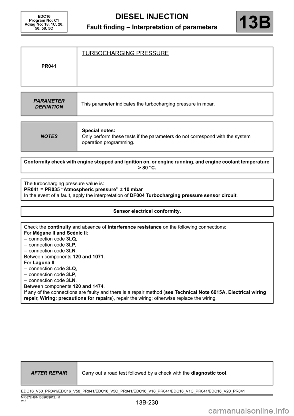
PR041
TURBOCHARGING PRESSURE
PARAMETER
DEFINITIONThis parameter indicates the turbocharging pressure in mbar.
NOTESSpecial notes:
Only perform these tests if the parameters do not correspond with the system
operation programming.
Conformity check with engine stopped and ignition on, or engine running, and engine coolant temperature
>80 °C.
The turbocharging pressure value is:
PR041 = PR035 “Atmospheric pressure” ± 10 mbar
In the event of a fault, apply the interpretation of DF004 Turbocharging pressure sensor circuit.
Sensor electrical conformity.
Check the continuity and absence of interference resistance on the following connections:
For Mégane II and Scénic II:
– connection code 3LQ,
– connection code 3LP,
– connection code 3LN.
Between components 120 and 1071.
For Laguna II:
– connection code 3LQ,
– connection code 3LP,
– connection code 3LN.
Between components 120 and 1474.
If any of the connections are faulty and there is a repair method (see Technical Note 6015A, Electrical wiring
repair, Wiring: precautions for repairs), repair the wiring; otherwise replace the wiring.
AFTER REPAIRCarry out a road test followed by a check with the diagnostic tool.
EDC16_V50_PR041/EDC16_V58_PR041/EDC16_V5C_PR041/EDC16_V18_PR041/EDC16_V1C_PR041/EDC16_V20_PR041
Page 231 of 365

13B-231
MR-372-J84-13B200$612.mif
V13
DIESEL INJECTION
Fault finding – Interpretation of parameters
EDC16
Program No: C1
Vdiag No: 18, 1C, 20,
50, 58, 5C
13B
PR041
CONTINUED
Vehicle with ignition on, and the engine stopped for over 1 minute:
Compare the values of PR041 and PR035 Atmospheric pressure.
If the difference between PR041 and PR035 Atmospheric pressure is greater than 0.1 bar,
check the value of PR035 Atmospheric pressure by comparing it with the reading on a vehicle in the workshop
which is correct.
If the value of PR035 Atmospheric pressure is not correct (difference greater than 0.1 bar between
the 2 vehicles), contact the Techline.
Otherwise (when the value PR035 Atmospheric pressure is correct), change the turbocharging pressure
sensor.
If the difference between PR041 and PR035 Atmospheric pressure is less than 0.1 bar.
Start the engine, with the engine idling:
Compare the values of PR041 and PR035 Atmospheric pressure.
If the difference between PR041 and PR035 Atmospheric pressure is greater than 0.2 bar.
Check the air inlet circuit:
absence of leaks or blockages in the low and high pressure air circuit: ducts, presence and tightness of the
mounting clips, mounting of the turbocharger pressure sensor, intercooler, etc.
Check that the damper valve is not jammed closed.
Repair if necessary.
AFTER REPAIRCarry out a road test, then check with the diagnostic tool.