display RENAULT SCENIC 2011 J95 / 3.G Engine And Peripherals Siemens Injection Owners Manual
[x] Cancel search | Manufacturer: RENAULT, Model Year: 2011, Model line: SCENIC, Model: RENAULT SCENIC 2011 J95 / 3.GPages: 329, PDF Size: 1.71 MB
Page 122 of 329

13B-122
MR-372-J84-13B050$468.mif
V17
DIESEL INJECTION
Fault finding – Interpretation of faults
Siemens Injection
SID301 and 304
Vdiag No.: 44-45-48-49-4D-4C
Program No.: B1 and B2
13B
DF1009
CONTINUED
Measure the resistance of the catalytic converter 1 downstream temperature sensor, component code 1765
between connections 3AGX and 3AGY.
6886Ω
sensor.
AFTER REPAIRDeal with any faults displayed by the diagnostic tool.
Clear the computer fault memory.
Carry out a road test followed by another check with the diagnostic tool.
Page 123 of 329
13B-123
MR-372-J84-13B050$468.mif
V17
DIESEL INJECTION
Fault finding – Interpretation of faults
Siemens Injection
SID301 and 304
Vdiag No.: 44-45-48-49-4D-4C
Program No.: B1 and B2
13B
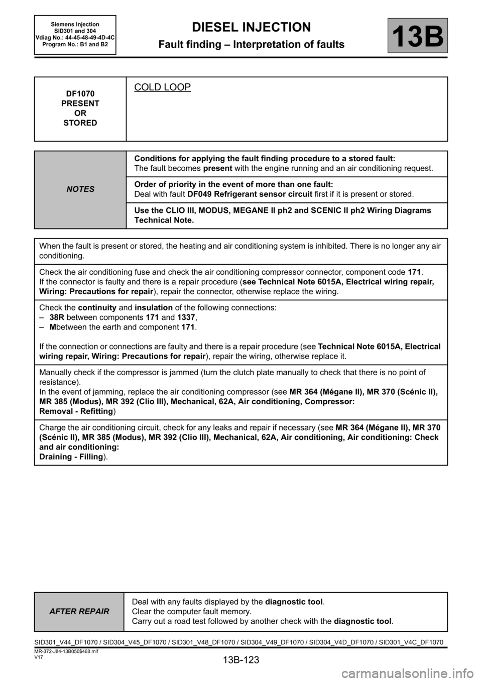
DF1070
PRESENT
OR
STOREDCOLD LOOP
NOTESConditions for applying the fault finding procedure to a stored fault:
The fault becomes present with the engine running and an air conditioning request.
Order of priority in the event of more than one fault:
Deal with fault DF049 Refrigerant sensor circuit first if it is present or stored.
Use the CLIO III, MODUS, MEGANE II ph2 and SCENIC II ph2 Wiring Diagrams
Technical Note.
When the fault is present or stored, the heating and air conditioning system is inhibited. There is no longer any air
conditioning.
Check the air conditioning fuse and check the air conditioning compressor connector, component code 171.
If the connector is faulty and there is a repair procedure (see Technical Note 6015A, Electrical wiring repair,
Wiring: Precautions for repair), repair the connector, otherwise replace the wiring.
Check the continuity and insulation of the following connections:
– 38R between components 171 and 1337,
– Mbetween the earth and component 171.
If the connection or connections are faulty and there is a repair procedure (see Technical Note 6015A, Electrical
wiring repair, Wiring: Precautions for repair), repair the wiring, otherwise replace it.
Manually check if the compressor is jammed (turn the clutch plate manually to check that there is no point of
resistance).
In the event of jamming, replace the air conditioning compressor (see MR 364 (Mégane II), MR 370 (Scénic II),
MR 385 (Modus), MR 392 (Clio III), Mechanical, 62A, Air conditioning, Compressor:
Removal - Refitting)
Charge the air conditioning circuit, check for any leaks and repair if necessary (see MR 364 (Mégane II), MR 370
(Scénic II), MR 385 (Modus), MR 392 (Clio III), Mechanical, 62A, Air conditioning, Air conditioning: Check
and air conditioning:
Draining - Filling).
AFTER REPAIRDeal with any faults displayed by the diagnostic tool.
Clear the computer fault memory.
Carry out a road test followed by another check with the diagnostic tool.
SID301_V44_DF1070 / SID304_V45_DF1070 / SID301_V48_DF1070 / SID304_V49_DF1070 / SID304_V4D_DF1070 / SID301_V4C_DF1070
Page 139 of 329
13B-139
MR-372-J84-13B050$585.mif
V17
Siemens Injection
SID301 and 304
Vdiag No.: 44-45-48-49-4D-4C
Program No.: B1 and B2DIESEL INJECTION
Fault finding – Interpretation of statuses13B
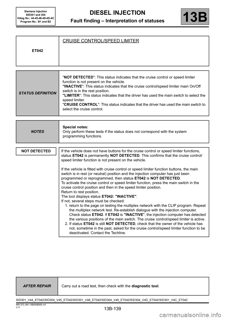
ET042
CRUISE CONTROL/SPEED LIMITER
STATUS DEFINITION"NOT DETECTED": This status indicates that the cruise control or speed limiter
function is not present on the vehicle.
"INACTIVE": This status indicates that the cruise control/speed limiter main On/Off
switch is in the rest position.
"LIMITER": This status indicates that the driver has used the main switch to select the
speed limiter.
"CRUISE CONTROL": This status indicates that the driver has used the main switch to
select the cruise control.
NOTESSpecial notes:
Only perform these tests if the status does not correspond with the system
programming functions.
NOT DETECTED
If the vehicle does not have buttons for the cruise control or speed limiter functions,
status ET042 is permanently NOT DETECTED. This confirms that the cruise control/
speed limiter function is not present on the vehicle.
If the vehicle is fitted with cruise control or speed limiter function buttons, the main
switch is in rest (or neutral) position and the injection computer has just been
programmed or reprogrammed, then status ET042 is NOT DETECTED.
To activate the cruise control or speed limiter function, press the main switch in the
cruise control position and then in the speed limiter position.
Return to rest position.
The tool displays status ET042: "INACTIVE".
If not, several steps must be checked:
1. return to the page on testing the multiplex network with the CLIP program. Repeat
the multiplex network test. Re-establish dialogue with the injection computer.
Check status ET042. If ET042 is "INACTIVE", the injection computer has detected
the various positions of the main switch. The cruise control/speed limiter is active.
2. If status ET042 is still NOT DETECTED, check that the owner of the vehicle has
not, sometime in the past, asked for the cruise control/speed limiter function to be
deactivated. Contact the Techline.
AFTER REPAIRCarry out a road test, then check with the diagnostic tool.
SID301_V44_ET042/SID304_V45_ET042/SID301_V48_ET042/SID304_V49_ET042/SID304_V4D_ET042/SID301_V4C_ET042
Page 157 of 329
13B-157
MR-372-J84-13B050$624.mif
V17
13B
DIESEL INJECTION
Fault finding – Interpretation of statuses
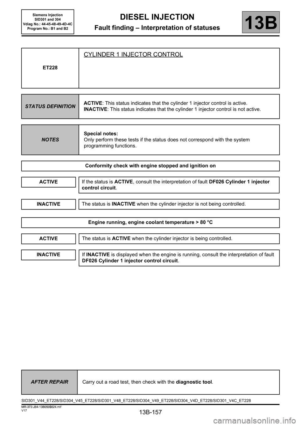
ET228
CYLINDER 1 INJECTOR CONTROL
STATUS DEFINITIONACTIVE: This status indicates that the cylinder 1 injector control is active.
INACTIVE: This status indicates that the cylinder 1 injector control is not active.
NOTESSpecial notes:
Only perform these tests if the status does not correspond with the system
programming functions.
Conformity check with engine stopped and ignition on
ACTIVE
Engine running, engine coolant temperature > 80 °C
ACTIVE
INACTIVE
If the status is ACTIVE, consult the interpretation of fault DF026 Cylinder 1 injector
control circuit.
The status is INACTIVE when the cylinder injector is not being controlled.
The status is ACTIVE when the cylinder injector is being controlled.
If INACTIVE is displayed when the engine is running, consult the interpretation of fault
DF026 Cylinder 1 injector control circuit.
INACTIVE
AFTER REPAIRCarry out a road test, then check with the diagnostic tool.
SID301_V44_ET228/SID304_V45_ET228/SID301_V48_ET228/SID304_V49_ET228/SID304_V4D_ET228/SID301_V4C_ET228
MR-372-J84-13B050$624.mif
Siemens Injection
SID301 and 304
Vdiag No.: 44-45-48-49-4D-4C
Program No.: B1 and B2
Page 158 of 329
13B-158
MR-372-J84-13B050$624.mif
V17
Siemens Injection
SID301 and 304
Vdiag No.: 44-45-48-49-4D-4C
Program No.: B1 and B2DIESEL INJECTION
Fault finding – Interpretation of statuses13B
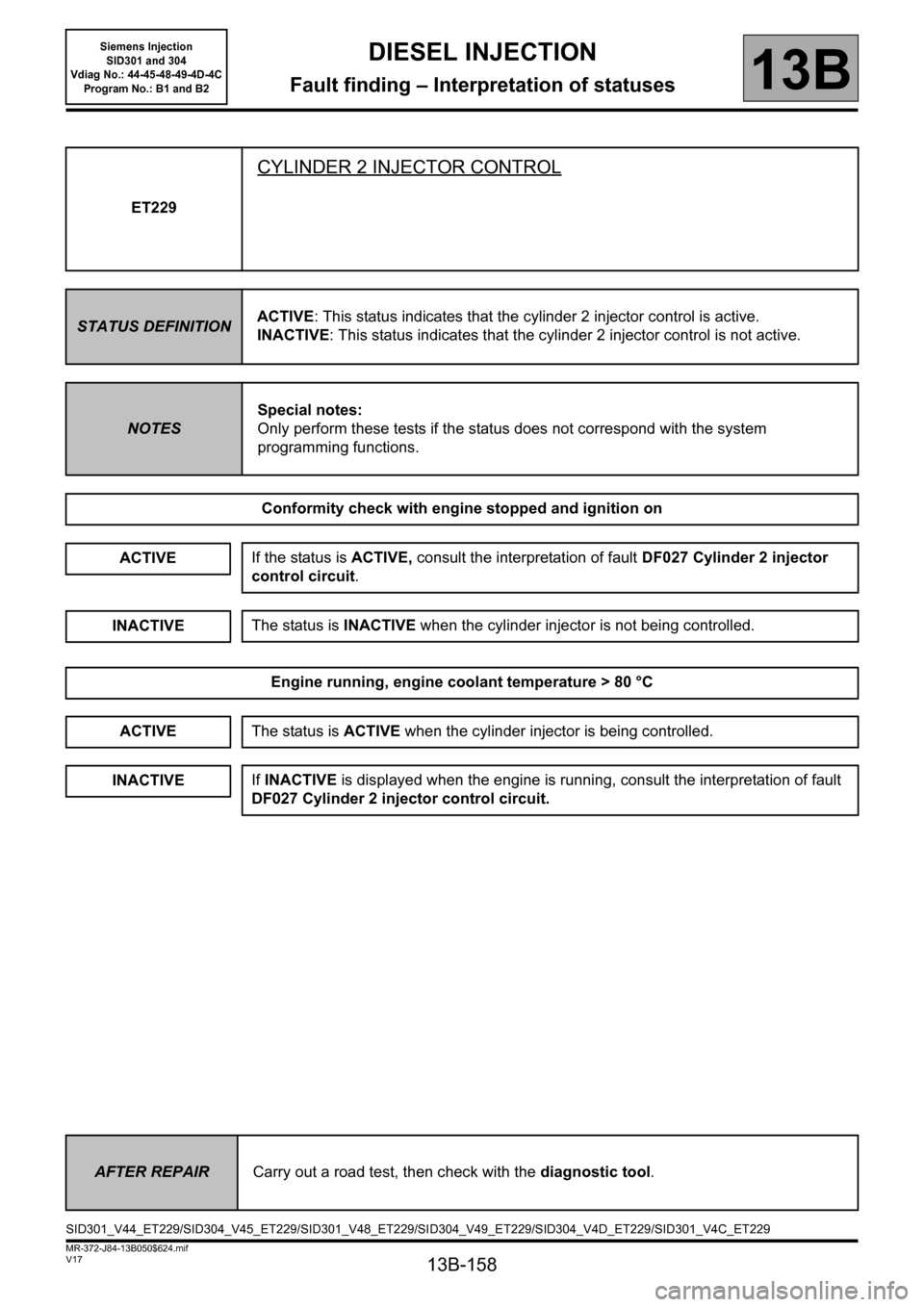
ET229
CYLINDER 2 INJECTOR CONTROL
STATUS DEFINITIONACTIVE: This status indicates that the cylinder 2 injector control is active.
INACTIVE: This status indicates that the cylinder 2 injector control is not active.
NOTESSpecial notes:
Only perform these tests if the status does not correspond with the system
programming functions.
Conformity check with engine stopped and ignition on
ACTIVE
Engine running, engine coolant temperature > 80 °C
If the status is ACTIVE, consult the interpretation of fault DF027 Cylinder 2 injector
control circuit.
INACTIVEThe status is INACTIVE when the cylinder injector is not being controlled.
ACTIVEThe status is ACTIVE when the cylinder injector is being controlled.
INACTIVEIf INACTIVE is displayed when the engine is running, consult the interpretation of fault
DF027 Cylinder 2 injector control circuit.
AFTER REPAIRCarry out a road test, then check with the diagnostic tool.
SID301_V44_ET229/SID304_V45_ET229/SID301_V48_ET229/SID304_V49_ET229/SID304_V4D_ET229/SID301_V4C_ET229
Page 159 of 329
13B-159
MR-372-J84-13B050$624.mif
V17
Siemens Injection
SID301 and 304
Vdiag No.: 44-45-48-49-4D-4C
Program No.: B1 and B2DIESEL INJECTION
Fault finding – Interpretation of statuses13B
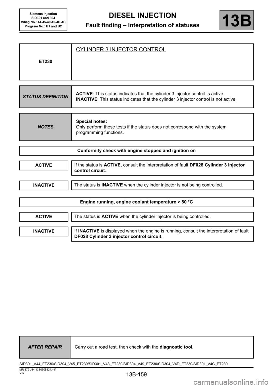
ET230
CYLINDER 3 INJECTOR CONTROL
STATUS DEFINITIONACTIVE: This status indicates that the cylinder 3 injector control is active.
INACTIVE: This status indicates that the cylinder 3 injector control is not active.
NOTESSpecial notes:
Only perform these tests if the status does not correspond with the system
programming functions.
Conformity check with engine stopped and ignition on
ACTIVE
Engine running, engine coolant temperature > 80 °C
If the status is ACTIVE, consult the interpretation of fault DF028 Cylinder 3 injector
control circuit.
INACTIVEThe status is INACTIVE when the cylinder injector is not being controlled.
ACTIVEThe status is ACTIVE when the cylinder injector is being controlled.
INACTIVEIf INACTIVE is displayed when the engine is running, consult the interpretation of fault
DF028 Cylinder 3 injector control circuit.
AFTER REPAIRCarry out a road test, then check with the diagnostic tool.
SID301_V44_ET230/SID304_V45_ET230/SID301_V48_ET230/SID304_V49_ET230/SID304_V4D_ET230/SID301_V4C_ET230
Page 160 of 329

13B-160
MR-372-J84-13B050$624.mif
V17
Siemens Injection
SID301 and 304
Vdiag No.: 44-45-48-49-4D-4C
Program No.: B1 and B2DIESEL INJECTION
Fault finding – Interpretation of statuses13B
ET231
CYLINDER 4 INJECTOR CONTROL
STATUS DEFINITIONACTIVE: This status indicates that the cylinder 4 injector control is active.
INACTIVE: This status indicates that the cylinder 4 injector control is not active.
NOTESSpecial notes:
Only perform these tests if the status does not correspond with the system
programming functions.
Conformity check with engine stopped and ignition on
ACTIVE
Engine running, engine coolant temperature > 80 °C
The status is INACTIVE when the cylinder injector is not being controlled.
If the status is ACTIVE, consult the interpretation of fault DF029 Cylinder 4 injector
control circuit.
INACTIVE
ACTIVEThe status is ACTIVE when the cylinder injector is being controlled.
INACTIVEIf INACTIVE is displayed when the engine is running, consult the interpretation of fault
DF029 Cylinder 4 injector control circuit.
AFTER REPAIRCarry out a road test, then check with the diagnostic tool.
SID301_V44_ET231/SID304_V45_ET231/SID301_V48_ET231/SID304_V49_ET231/SID304_V4D_ET231/SID301_V4C_ET231
Page 177 of 329
13B-177
MR-372-J84-13B050$624.mif
V17
13B
DIESEL INJECTION
Fault finding – Interpretation of statuses
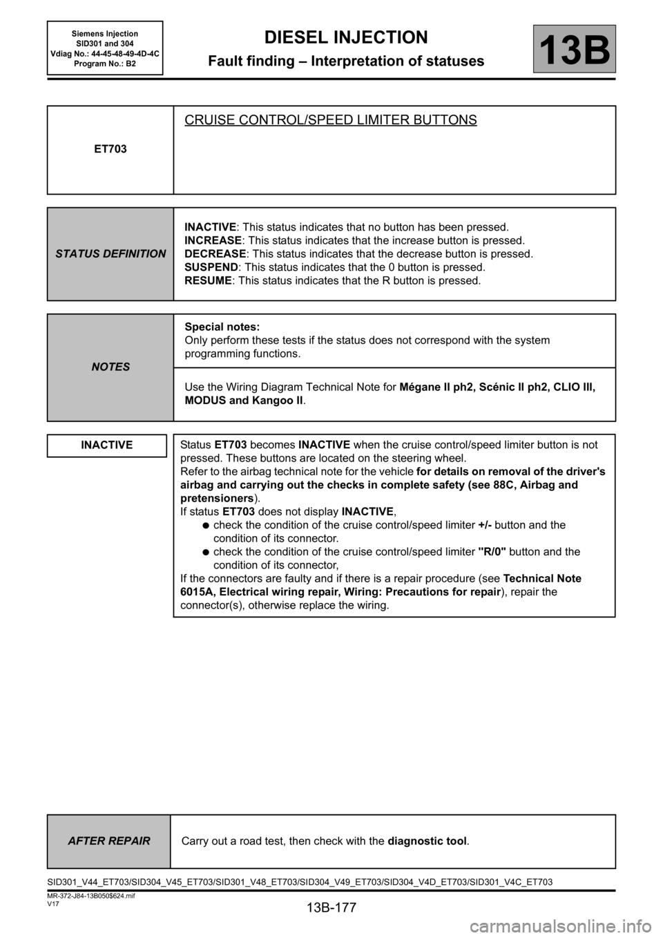
ET703
CRUISE CONTROL/SPEED LIMITER BUTTONS
STATUS DEFINITIONINACTIVE: This status indicates that no button has been pressed.
INCREASE: This status indicates that the increase button is pressed.
DECREASE: This status indicates that the decrease button is pressed.
SUSPEND: This status indicates that the 0 button is pressed.
RESUME: This status indicates that the R button is pressed.
NOTESSpecial notes:
Only perform these tests if the status does not correspond with the system
programming functions.
Use the Wiring Diagram Technical Note for Mégane II ph2, Scénic II ph2, CLIO III,
MODUS and Kangoo II.
INACTIVE
Status ET703 becomes INACTIVE when the cruise control/speed limiter button is not
pressed. These buttons are located on the steering wheel.
Refer to the airbag technical note for the vehicle for details on removal of the driver's
airbag and carrying out the checks in complete safety (see 88C, Airbag and
pretensioners).
If status ET703 does not display INACTIVE,
●check the condition of the cruise control/speed limiter +/- button and the
condition of its connector.
●check the condition of the cruise control/speed limiter "R/0" button and the
condition of its connector,
If the connectors are faulty and if there is a repair procedure (see Te c h n i c a l N o t e
6015A, Electrical wiring repair, Wiring: Precautions for repair), repair the
connector(s), otherwise replace the wiring.
AFTER REPAIRCarry out a road test, then check with the diagnostic tool.
SID301_V44_ET703/SID304_V45_ET703/SID301_V48_ET703/SID304_V49_ET703/SID304_V4D_ET703/SID301_V4C_ET703
Siemens Injection
SID301 and 304
Vdiag No.: 44-45-48-49-4D-4C
Program No.: B2
Page 178 of 329
13B-178
MR-372-J84-13B050$624.mif
V17
Siemens Injection
SID301 and 304
Vdiag No.: 44-45-48-49-4D-4C
Program No.: B2DIESEL INJECTION
Fault finding – Interpretation of statuses13B
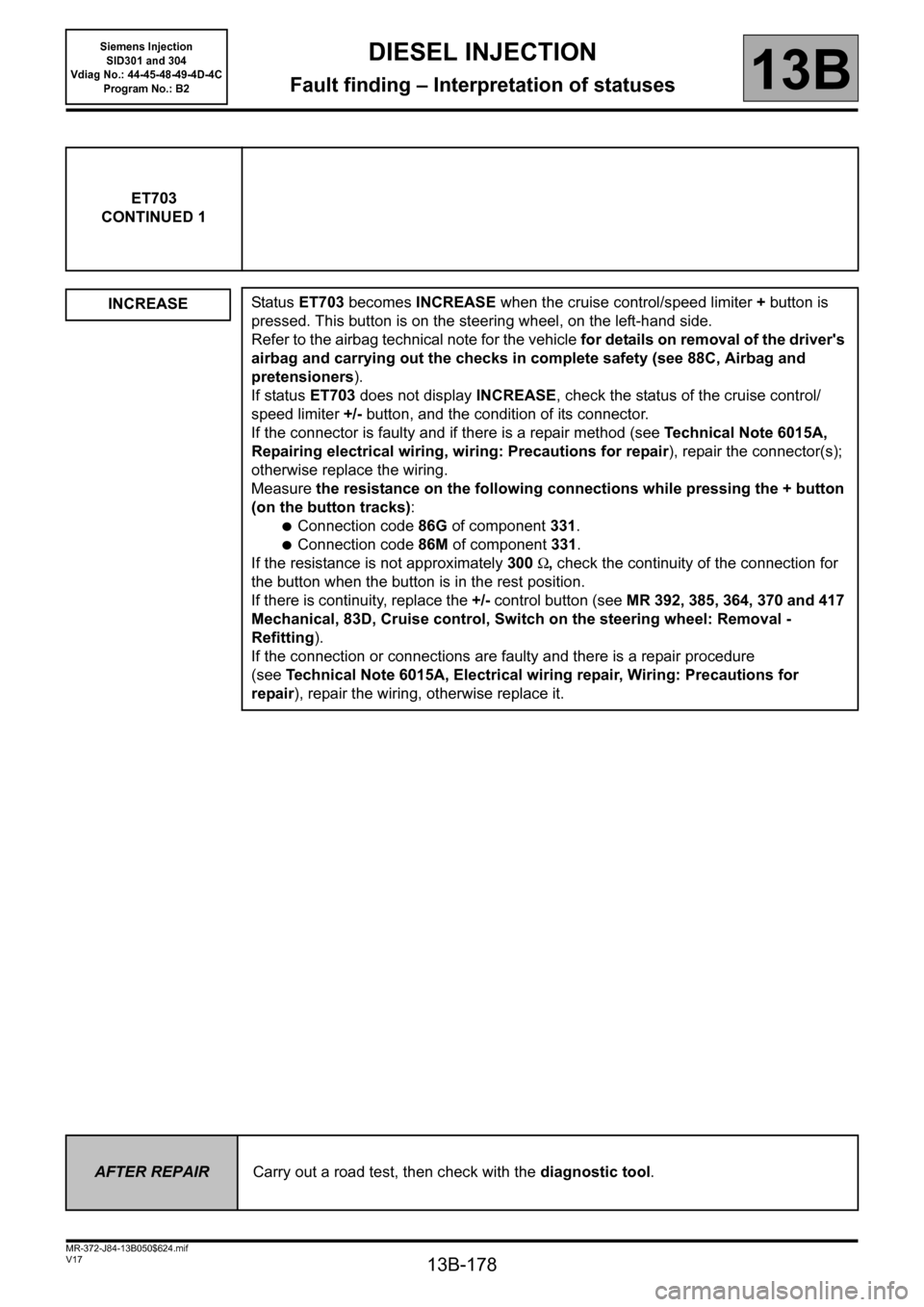
ET703
CONTINUED 1
INCREASE
Status ET703 becomes INCREASE when the cruise control/speed limiter + button is
pressed. This button is on the steering wheel, on the left-hand side.
Refer to the airbag technical note for the vehicle for details on removal of the driver's
airbag and carrying out the checks in complete safety (see 88C, Airbag and
pretensioners).
If status ET703 does not display INCREASE, check the status of the cruise control/
speed limiter +/- button, and the condition of its connector.
If the connector is faulty and if there is a repair method (see Technical Note 6015A,
Repairing electrical wiring, wiring: Precautions for repair), repair the connector(s);
otherwise replace the wiring.
Measure the resistance on the following connections while pressing the + button
(on the button tracks):
●Connection code86G of component 331.
●Connection code 86M of component 331.
If the resistance is not approximately 300Ω, check the continuity of the connection for
the button when the button is in the rest position.
If there is continuity, replace the +/- control button (see MR 392, 385, 364, 370 and 417
Mechanical, 83D, Cruise control, Switch on the steering wheel: Removal -
Refitting).
If the connection or connections are faulty and there is a repair procedure
(seeTechnical Note 6015A, Electrical wiring repair, Wiring: Precautions for
repair), repair the wiring, otherwise replace it.
AFTER REPAIRCarry out a road test, then check with the diagnostic tool.
Page 189 of 329
13B-189
MR-372-J84-13B050$702.mif
V17
13B
DIESEL INJECTION
Fault finding – Interpretation of parameters
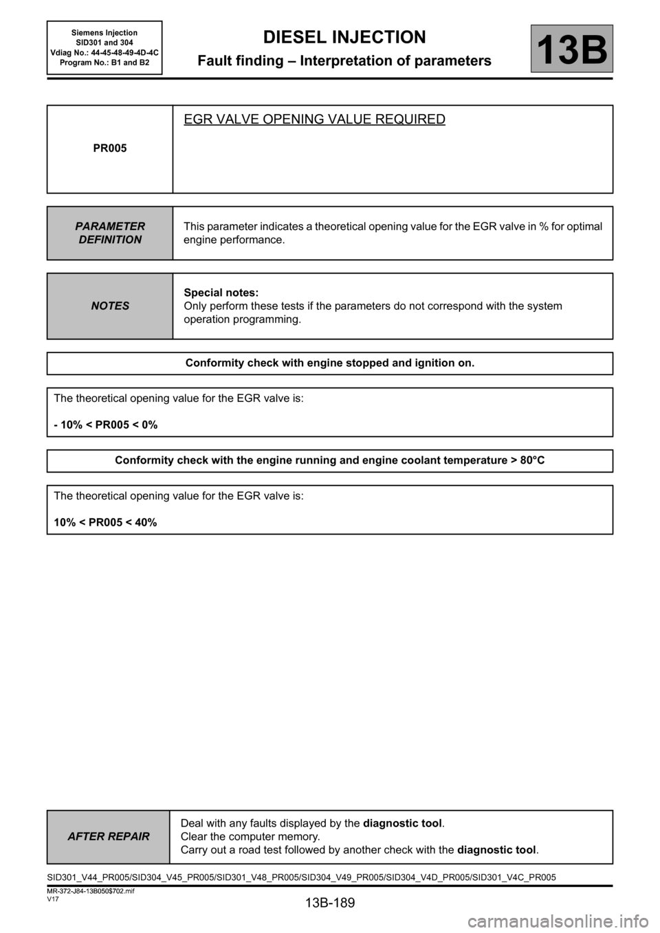
PR005
EGR VALVE OPENING VALUE REQUIRED
PARAMETER
DEFINITIONThis parameter indicates a theoretical opening value for the EGR valve in % for optimal
engine performance.
NOTESSpecial notes:
Only perform these tests if the parameters do not correspond with the system
operation programming.
Conformity check with engine stopped and ignition on.
The theoretical opening value for the EGR valve is:
- 10% < PR005 < 0%
Conformity check with the engine running and engine coolant temperature > 80°C
The theoretical opening value for the EGR valve is:
10% < PR005 < 40%
AFTER REPAIRDeal with any faults displayed by the diagnostic tool.
Clear the computer memory.
Carry out a road test followed by another check with the diagnostic tool.
SID301_V44_PR005/SID304_V45_PR005/SID301_V48_PR005/SID304_V49_PR005/SID304_V4D_PR005/SID301_V4C_PR005
MR-372-J84-13B050$702.mif
Siemens Injection
SID301 and 304
Vdiag No.: 44-45-48-49-4D-4C
Program No.: B1 and B2