engine RENAULT TWINGO 2009 2.G Engine And Peripherals Workshop Manual
[x] Cancel search | Manufacturer: RENAULT, Model Year: 2009, Model line: TWINGO, Model: RENAULT TWINGO 2009 2.GPages: 652
Page 162 of 652

11A-45
TOP AND FRONT OF ENGINE
Timing belt: Removal - Refitting
K9K
11A
aRemove a bolt from the camshaft pulley wheel (25) .
aLoosen the two other camshaft pulley wheel bolts by
one turn.
14489
109042
Page 163 of 652
11A-46
TOP AND FRONT OF ENGINE
Timing belt: Removal - Refitting
K9K
11A
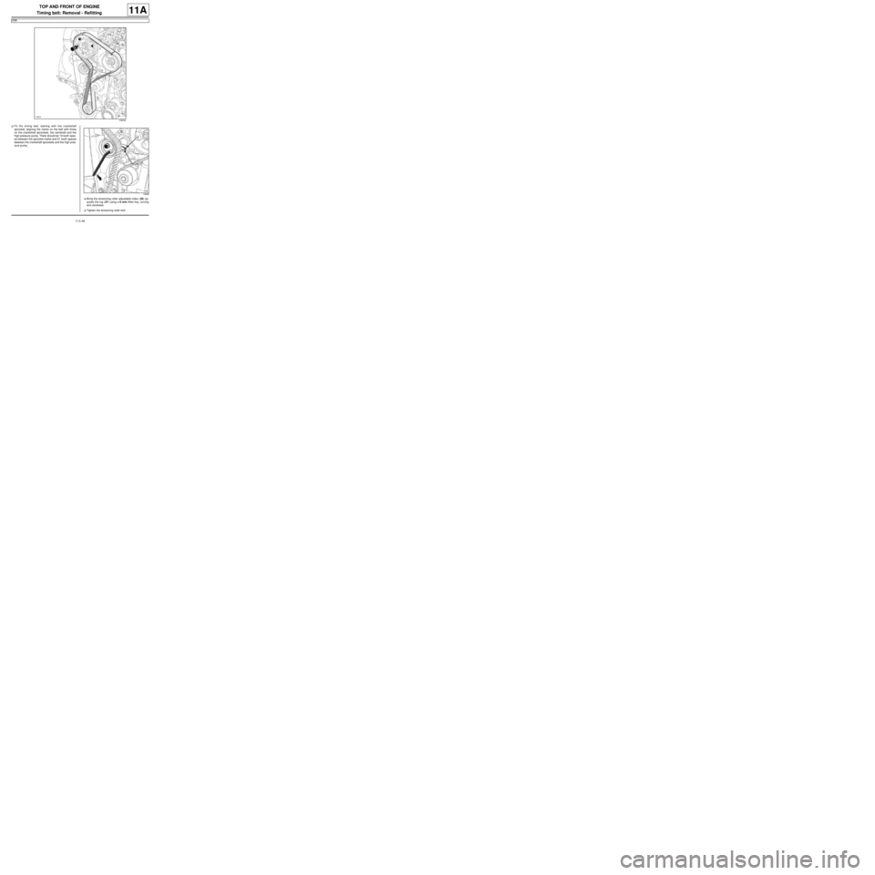
aFit the timing belt, starting with the crankshaft
sprocket, aligning the marks on the belt with those
on the crankshaft sprockets, the camshaft and the
high-pressure pump. There should be 19 tooth spac-
es between the sprocket marks and 51 tooth spaces
between the crankshaft sprockets and the high pres-
sure pump.
aBring the tensioning roller adjustable index (26) op-
posite the lug (27) using a 6 mm Allen key, turning
anti-clockwise.
aTighten the tensioning roller bolt.
109044
19658
Page 164 of 652
11A-47
TOP AND FRONT OF ENGINE
Timing belt: Removal - Refitting
K9K
11A
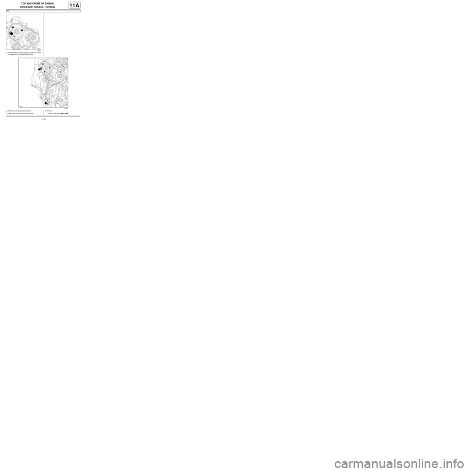
aCheck that the camshaft pulley hub bolts are not ful-
ly up against the camshaft pulley wheel.
aRefit the camshaft pulley wheel bolt.
aTighten the camshaft pulley wheel bolts.aRemove:
-the TDC setting pin (Mot. 1489),
109047
109045
Page 165 of 652
11A-48
TOP AND FRONT OF ENGINE
Timing belt: Removal - Refitting
K9K
11A
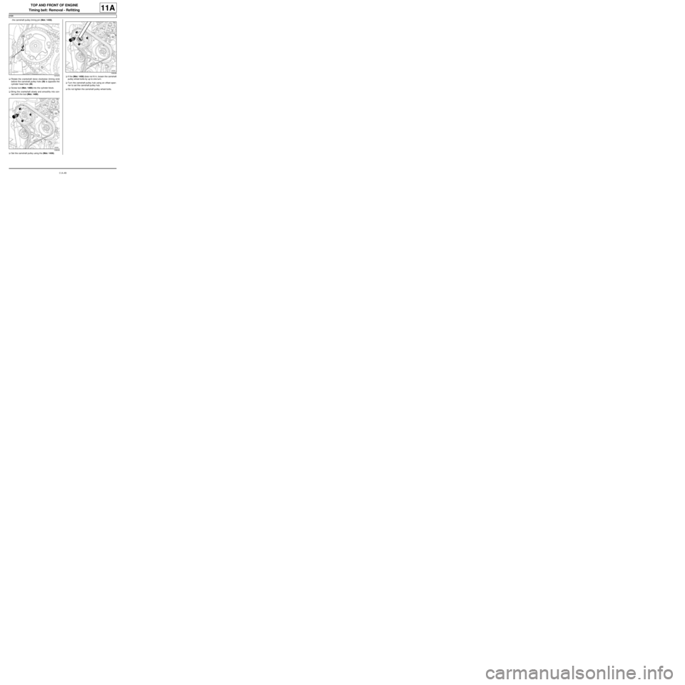
-the camshaft pulley timing pin (Mot. 1430).
aRotate the crankshaft twice clockwise (timing end)
before the camshaft pulley hole (28) is opposite the
cylinder head hole (29) .
aScrew tool (Mot. 1489) into the cylinder block.
aBring the crankshaft slowly and smoothly into con-
tact with the tool (Mot. 1489).
aSet the camshaft pulley using the (Mot. 1430).aIf the (Mot. 1430) does not fit in, loosen the camshaft
pulley wheel bolts by up to one turn.
aTurn the camshaft pulley hub using an offset span-
ner to set the camshaft pulley hub.
aDo not tighten the camshaft pulley wheel bolts.
107270
109049
109048
Page 166 of 652
11A-49
TOP AND FRONT OF ENGINE
Timing belt: Removal - Refitting
K9K
11A
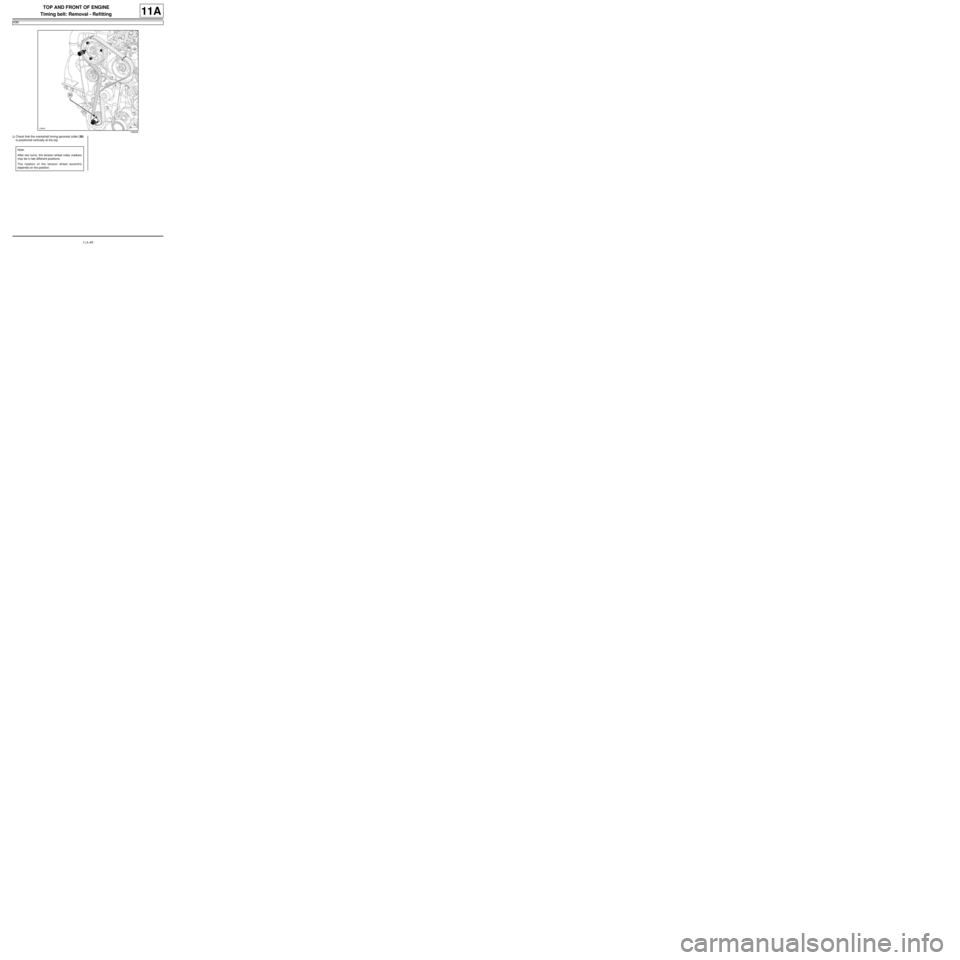
aCheck that the crankshaft timing sprocket collet (30)
is positioned vertically at the top.
109045
Note:
After two turns, the tension wheel index markers
may be in two different positions.
The rotation of the tension wheel eccentric
depends on the position.
Page 167 of 652
11A-50
TOP AND FRONT OF ENGINE
Timing belt: Removal - Refitting
K9K
11A
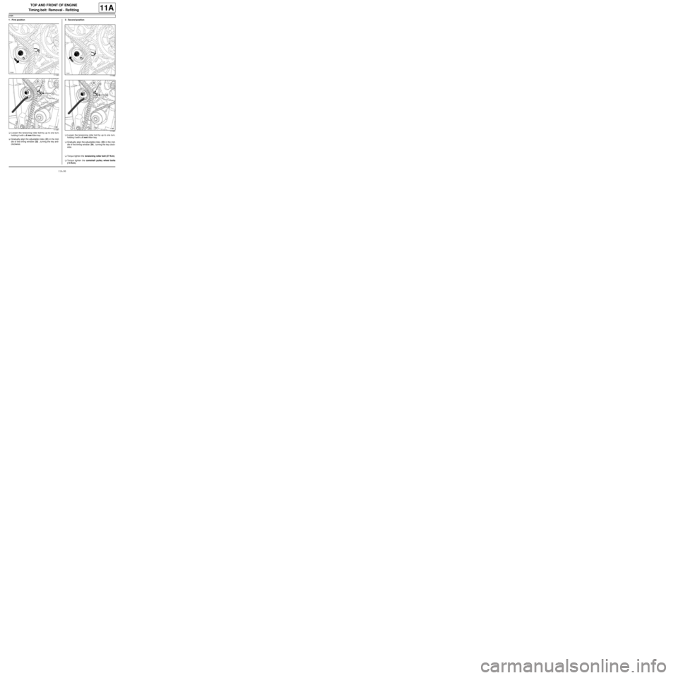
1 - First position
aLoosen the tensioning roller bolt by up to one turn,
holding it with a 6 mm Allen key.
aGradually align the adjustable index (31) in the mid-
dle of the timing window (32) , turning the key anti-
clockwise.2 - Second position
aLoosen the tensioning roller bolt by up to one turn,
holding it with a 6 mm Allen key.
aGradually align the adjustable index (33) in the mid-
dle of the timing window (34) , turning the key clock-
wise.
aTorque tighten the tensioning roller bolt (27 N.m).
aTorque tighten the camshaft pulley wheel bolts
(14 N.m).
111083
111081111082
111081
Page 168 of 652
11A-51
TOP AND FRONT OF ENGINE
Timing belt: Removal - Refitting
K9K
11A
aRemove:
-the (Mot. 1489),
-the (Mot. 1430).
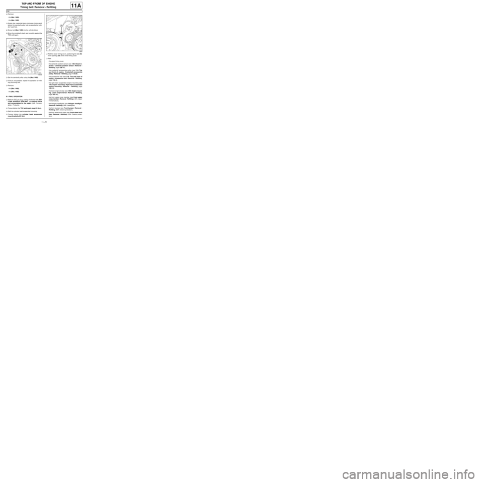
aRotate the crankshaft twice clockwise (timing end)
before the camshaft pulley hole is opposite the cylin-
der head hole.
aScrew tool (Mot. 1489) into the cylinder block.
aBring the crankshaft slowly and smoothly against the
TDC setting pin.
aSet the camshaft pulley using the (Mot. 1430).
aIf this is not possible, repeat the operation for refit-
ting the timing belt.
aRemove:
-the (Mot. 1489),
-the (Mot. 1430).
III - FINAL OPERATION
aRefit the TDC pin plug, coating the thread with SILI-
CONE ADHESIVE SEALANT (see Vehicle: Parts
and consumables for the repair) (04B, Consum-
ables - Products).
aTorque tighten the TDC setting pin plug (25 N.m).
aRefit the cylinder head suspended mounting .
aTorque tighten the cylinder head suspended
mounting bolts (25 Nm).aRefit the lower timing cover, positioning the tab (35)
in the opening (36) of the inner timing cover.
aRefit:
-the upper timing cover,
-the camshaft position sensor (see 13B, Diesel in-
jection, Camshaft position sensor: Removal -
Refitting, page 13B-14) ,
-the crankshaft accessories pulley (see 11A, Top
and front of engine, Crankshaft accessories
pulley: Removal - Refitting, page 11A-20) ,
-the accessories belt (see 11A, Top and front of
engine, Accessories belt: Removal - Refitting,
page 11A-3) ,
-the right-hand suspended engine mounting (see
19D, Engine mounting, Right-hand suspended
engine mounting: Removal - Refitting, page
19D-13) ,
-the lower engine tie-bar (see 19D, Engine mount-
ing, Lower engine tie-bar: Removal - Refitting,
page 19D-18) ,
-the front upper cross member (see Front upper
cross member: Removal - Refitting) (42A, Upper
front structure),
-the halogen headlights (see Halogen headlight:
Removal - Refitting) (80B, Headlights),
-the front bumper (see Front bumper: Removal -
Refitting) (55A, Exterior protection),
-the front wheel arch liners (see Front wheel arch
liner: Removal - Refitting) (55A, Exterior protec-
tion),
109049
19659
Page 169 of 652
11A-52
TOP AND FRONT OF ENGINE
Timing belt: Removal - Refitting
K9K
11A
-the front wheels (see Wheel: Removal - Refitting)
(35A, Wheels and tyres),
-the scoop under the scuttle panel grille (see Scoop
under the scuttle panel grille: Removal - Refit-
ting) (56A, Exterior equipment),
-the scuttle panel grille (see Scuttle panel grille:
Removal - Refitting) (56A, Exterior equipment),
-the windscreen wiper arms (see Windscreen wip-
er arm: Removal - Refitting) (85A, Wiping -
Washing),
-the engine cover.
aConnect the battery (see Battery: Removal - Refit-
ting) (80A, Battery).
Page 170 of 652
11A-53
TOP AND FRONT OF ENGINE
Timing belt: Removal - Refitting
K4M
11A
REMOVAL
I - REMOVAL PREPARATION OPERATION
aPosition the vehicle on a two-post lift (see Vehicle:
Towing and lifting) (02A, Lifting equipment).
aDisconnect the battery (see Battery: Removal - Re-
fitting) (80A, Battery).
aRemove:
-the engine undertray,
-the front right-hand wheel (see Wheel: Removal -
Refitting) (35A, Wheels and tyres),
-the front right-hand wheel arch liner (see Front
wheel arch liner: Removal - Refitting) (55A, Ex-
terior protection),
-the front bumper (see Front bumper: Removal -
Refitting) (55A, Exterior protection),
-the headlights (see Halogen headlight: Removal
- Refitting) (80B, Headlights),
-the bonnet catch (see Bonnet lock: Removal -
Refitting) (52A, Non-side opening element mecha-
nisms),
-the front upper cross member (see Front upper
cross member: Removal - Refitting) (42A, Upper
front structure),
-the accessories belt (see 11A, Top and front of
engine, Accessories belt: Removal - Refitting,
page 11A-3) ,
-the air filter unit (see 12A, Fuel mixture, Air filter
unit: Removal - Refitting, page 12A-13) ,
-the throttle valve (see 12A, Fuel mixture, Throttle
valve: Removal - Refitting, page 12A-20) ,
-the windscreen wiper arms (see Windscreen wip-
er arm: Removal - Refitting) (85A, Wiping -
Washing),
-the scuttle panel grille (see Scuttle panel grille:
Removal - Refitting) (56A, Exterior equipment), Special tooling required
Mot. 1489TDC locating pin.
Mot. 1368Tool for tightening eccentric
tensioning roller bolt. 8 mm
Torx wrench and 12.7 mm
square.
Mot. 1496Camshaft timing tool.
Mot. 1750Additional tool to suppor t the
camshaft adjusting tool, Mot.
1496.
Mot. 1490-01For locking and adjusting the
camshaft pulle ys.
Mot. 1487Tool for refitting camshaft cov-
ers (57 mm diameter).
Mot. 1488Tool for refitting camshaft cov-
ers (43 mm diameter).
Equipment required
indelible pencil
Tightening torquesm
fixed roller bolt50 N.m
lower timing cover bolts12 N.m
exhaust camshaft pul-
ley nut30 N.m + 84˚
camshaft dephaser pul-
ley bolt100 N.m
timing tension wheel nut27 N.m
TDC setting pin plug20 N.m
upper timing cover bolts41 N.m
upper timing cover nuts41 N.m
rear suspended engine
reinforcement bolt105 N.m
rear suspended engine
mounting bolt on the
rear suspended engine
mounting suppor t105 N.m
rear suspended engine
mounting bolt on the
subframe105 N.m Tightening torquesm
Page 171 of 652

11A-54
TOP AND FRONT OF ENGINE
Timing belt: Removal - Refitting
K4M
11A
-the scoop under the scuttle panel grille (see Scoop
under the scuttle panel grille: Removal - Refit-
ting) (56A, Exterior equipment).
aRemove:
-the rear suspended engine mounting bolt (1) from
the subframe,
-the rear suspended engine mounting bolt (2) from
the rear suspended engine mounting support,
-the rear suspended engine mounting reinforce-
ment bolt (3) ,
-the rear suspended engine mounting,
-the right-hand suspended engine mounting (see
19D, Engine mounting, Right-hand suspended
engine mounting: Removal - Refitting, page
19D-13) .aDisconnect the upstream oxygen sensor connector
(4) .
aUnclip the wiring from the upstream oxygen sensor
at (5) .
aMove the upstream oxygen sensor wiring aside.
aUnclip the connector (6) from the lifting eye.
aRemove the lifting eye bolts (7) .
131769
132373
103271