engine RENAULT TWINGO 2009 2.G Engine And Peripherals Workshop Manual
[x] Cancel search | Manufacturer: RENAULT, Model Year: 2009, Model line: TWINGO, Model: RENAULT TWINGO 2009 2.GPages: 652
Page 280 of 652

12A-15
FUEL MIXTURE
Air filter unit: Removal - Refitting
K9K
12A
REMOVAL
I - REFITTING OPERATION FOR PART
CONCERNED
aSlide the air filter box towards the gearbox side.
aCheck the condition of the air filter box mountings,
replace them if necessary.
aClip:
-the air filter box onto its mountings,
-the air filter air outlet pipe to the air filter.
aTighten the air pipe clip on the air filter outlet.
aRefit the air filter air inlet pipe on the vehicle.
aPosition the turbocharger pressure sensor on the air
filter box.
aRefit the bolt mounting the turbocharger pressure
sensor on the air filter box.
aConnect the connectors:
-of the inlet air temperature sensor,
-of the turbocharging pressure sensor,
-of the flow sensor,
-of the EGR.
aClip on the air filter box harnesses.
aClip the air filter inlet air pipe to the air filter box.
II - FINAL OPERATION.
aRefit the engine cover.Note:
Ensure that the centring lug of the box is fully
inserted in the cylinder head.
Page 284 of 652
12A-19
FUEL MIXTURE
Air resonator: Removal - Refitting
K4M
12A
REMOVAL
I - REMOVAL PREPARATION OPERATION
aPosition the vehicle on a two-post lift (see Vehicle:
Towing and lifting) (02A, Lifting equipment).
aRemove:
-the engine undertray,
-the front left-hand wheel (see Wheel: Removal -
Refitting) (35A, Wheels and tyres),
-the front left-hand wheel arch liner (see Front
wheel arch liner: Removal - Refitting) (55A, Ex-
terior protection).
II - REMOVAL OPERATION
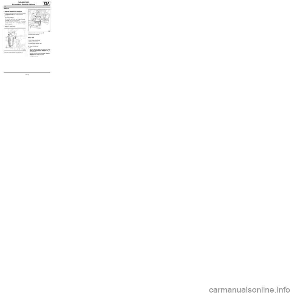
aRemove the air resonator mounting bolts (1) .aDisconnect the air resonator pipe (2) .
aRemove the air resonator .
REFITTING
I - REFITTING OPERATION
aRefit the air resonator.
aConnect the air resonator pipe.
II - FINAL OPERATION
aRefit:
-the front left-hand wheel arch liner (see Front
wheel arch liner: Removal - Refitting) (55A, Ex-
terior protection),
-the front left-hand wheel (see Wheel: Removal -
Refitting) (35A, Wheels and tyres),
-the engine undertray.
131764
131765
Page 295 of 652
12A-30
FUEL MIXTURE
Inlet distributor: Removal - Refitting
D7F
12A
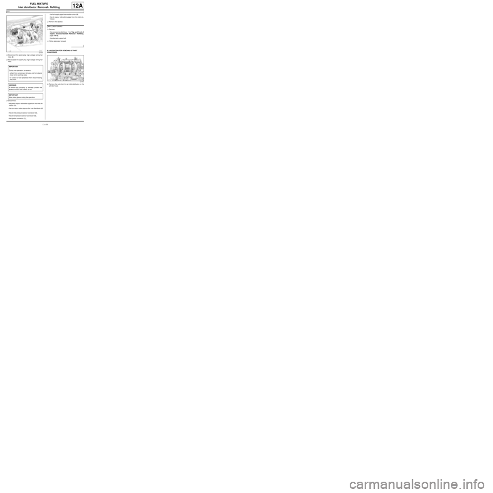
aDisconnect the spark plug high voltage wiring har-
ness (2) .
aMove aside the spark plug high voltage wiring har-
ness.
aDisconnect:
-the petrol vapour rebreather pipe from the inlet dis-
tributor (3) ,
-the non-return valve pipe on the inlet distributor (4)
,
-the air inlet pressure sensor connector (5) ,
-the air temperature sensor connector (6) ,
-the injector connector (7) ,-the fuel supply pipe intermediate union (8) ,
-the oil vapour rebreathing pipe from the inlet dis-
tributor.
aRemove the dipstick.
aRemove:
-the accessories belt (see 11A, Top and front of
engine, Accessories belt: Removal - Refitting,
page 11A-3) ,
-the alternator upper bolt.
aTilt the alternator forward.
II - OPERATION FOR REMOVAL OF PART
CONCERNED
aRemove the nuts from the air inlet distributor on the
cylinder head.
121737
IMPORTANT
During this operation, be sure to:
-refrain from smoking or bringing red hot objects
close to the working area,
-be careful of fuel splashes when disconnecting
the union.
WARNING
To avoid any corrosion or damage, protect the
areas on which fuel is likely to run.
IMPORTANT
Wear latex gloves during the operation.
AIR CONDITIONING
121734
Page 297 of 652
12A-32
FUEL MIXTURE
Inlet distributor: Removal - Refitting
D7F
12A
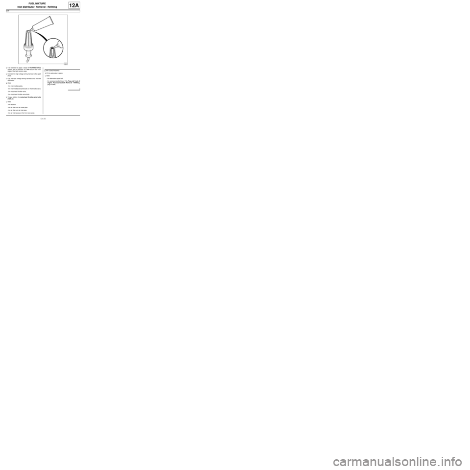
aIt is essential to apply a bead of FLUORSTAR 2L
grease with a diameter of 2 mm around the inner
edge of the high tension caps.
aConnect the high voltage wiring harness to the spark
plugs.
aClip the high voltage wiring harness onto the inlet
distributor.
aRefit:
-the intermediate plate,
-the intermediate bracket bolts on the throttle valve,
-the motorised throttle valve,
-the motorised throttle valve bolts.
aTorque tighten the motorised throttle valve bolts
(10 N.m)
aRefit:
-the dipstick,
-the air filter unit air outlet pipe.
-the air filter unit air inlet pipe,
-the air inlet scoop on the front end panel.aFit the alternator in place.
aRefit:
-the alternator upper bolt,
-the accessories belt (see 11A, Top and front of
engine, Accessories belt: Removal - Refitting,
page 11A-3) .
106640
AIR CONDITIONING
Page 298 of 652
12A-33
FUEL MIXTURE
Inlet distributor: Removal - Refitting
D4F, and 772
12A
REMOVAL
I - REMOVAL PREPARATION OPERATION
aRemove the air filter unit (see 12A, Fuel mixture,
Air filter unit: Removal - Refitting, page 12A-13) .
aUnclip the fuel supply pipe on the engine oil filler
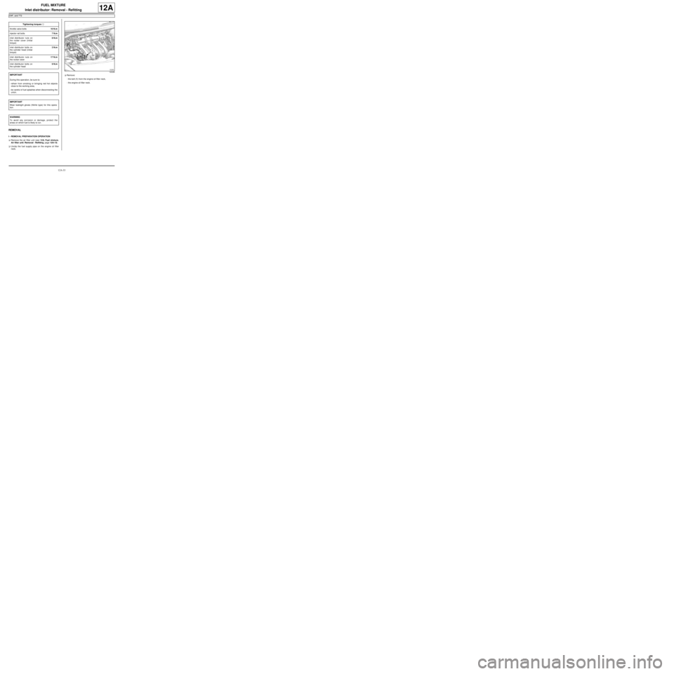
neck.aRemove:
-the bolt (1) from the engine oil filler neck,
-the engine oil filler neck. Tightening torquesm
throttle valve bolts10 N.m
injector rail bolts7 N.m
inlet distributor nuts on
the rocker cover (initial
torque)8 N.m
inlet distributor bolts on
the cylinder head (initial
torque)3 N.m
inlet distributor nuts on
the rocker cover17 N.m
inlet distributor bolts on
the cylinder head9 N.m
IMPORTANT
During this oper ation, be sure to:
-refrain from smoking or bringing red hot objects
close to the working area,
-be careful of fuel splashes when disconnecting the
union.
IMPORTANT
Wear leaktight gloves (Nitrile type) for this opera-
tion.
WARNING
To avoid any corrosion or damage, protect the
areas on which fuel is likely to run.
120299
Page 299 of 652
12A-34
FUEL MIXTURE
Inlet distributor: Removal - Refitting
D4F, and 772
12A
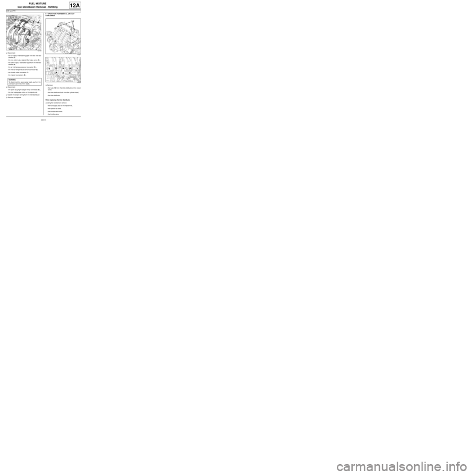
aDisconnect:
-the oil vapour rebreathing pipe from the inlet dis-
tributor (2) ,
-the non-return valve pipe on the brake servo (3) ,
-the petrol vapour rebreather pipe from the inlet dis-
tributor (4) ,
-the air inlet pressure sensor connector (5) ,
-the inlet air temperature sensor connector (6)
-the throttle valve connector (7) ,
-the injector connectors (8) .
aDisconnect:
-the spark plug high voltage wiring harnesses (9) ,
-the fuel supply pipe union on the injector rail.
aUnpick the engine wiring from the inlet distributor.
aRemove the dipstick.II - OPERATION FOR REMOVAL OF PART
CONCERNED
aRemove:
-the nuts (10) from the inlet distributor on the rocker
cover,
-the inlet distributor bolts from the cylinder head,
-the inlet distributor.
When replacing the inlet distributor
aUsing the workbench, remove:
-the fuel supply pipe to the injector rail,
-the injector rail bolts,
-the throttle valve bolts,
-the throttle valve.
121733
WARNING
To disconnect the spark plug leads, pull on the
extensions and not on the leads.
110421
109729
Page 301 of 652
12A-36
FUEL MIXTURE
Inlet distributor: Removal - Refitting
D4F, and 772
12A
III - FINAL OPERATION
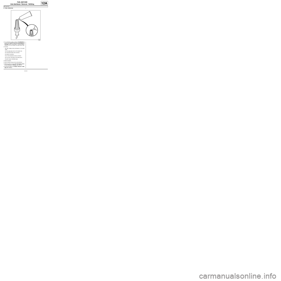
aIt is essential to apply a bead of FLUOSTAR 2L
grease (see Vehicle: Parts and consumables for
the repair) (04B, Consumables - Products) 2 mm in
diameter on the inner edge of the high tension caps.
aConnect:
-the high voltage wiring harnesses to the spark
plugs,
-the fuel supply pipe union on the injector rail,
-the motorised throttle valve connector,
-the injector connectors,
-the air inlet temperature sensor connector,
-the non-return valve pipe on the brake servo,
-the petrol vapour rebreather pipe.
aRefit the dipstick.
aClip the engine wiring onto the inlet distributor.
aRefit the air filter unit (see 12A, Fuel mixture, Air fil-
ter unit: Removal - Refitting, page 12A-13) .
aConnect the battery (see Battery: Removal - Refit-
ting) (80A, Battery).
106640
Page 302 of 652
12A-37
FUEL MIXTURE
Inlet distributor: Removal - Refitting
D4F, and 780 or 782
12A
REMOVAL
I - REMOVAL PREPARATION OPERATION
aRemove the throttle valve (see 12A, Fuel mixture,
Throttle valve: Removal - Refitting, page 12A-20)
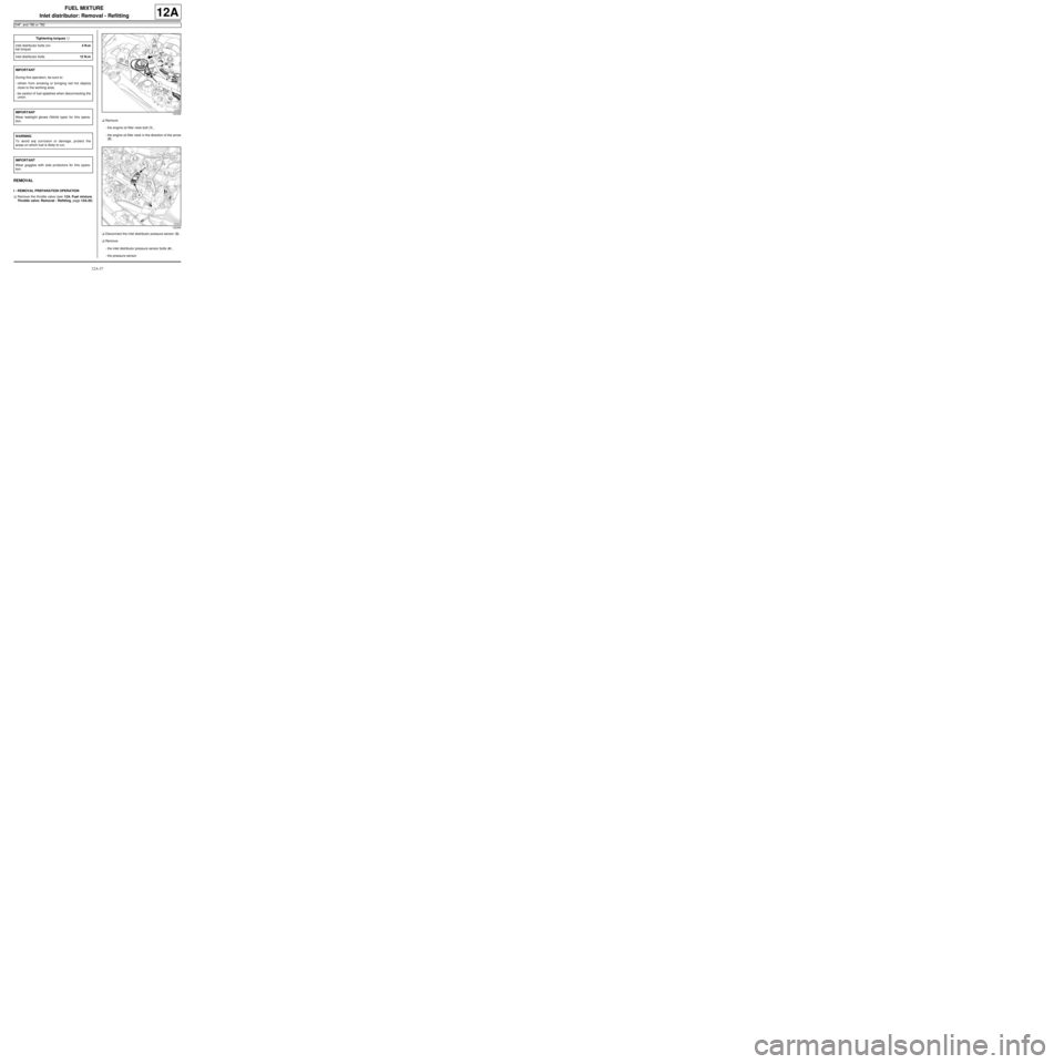
.aRemove:
-the engine oil filler neck bolt (1) ,
-the engine oil filler neck in the direction of the arrow
(2) .
aDisconnect the inlet distributor pressure sensor (3) .
aRemove:
-the inlet distributor pressure sensor bolts (4) ,
-the pressure sensor. Tightening torquesm
inlet distributor bolts (ini-
tial torque)4 N.m
inlet distributor bolts12 N.m
IMPORTANT
During this oper ation, be sure to:
-refrain from smoking or bringing red hot objects
close to the working area,
-be careful of fuel splashes when disconnecting the
union.
IMPORTANT
Wear leaktight gloves (Nitrile type) for this opera-
tion.
WARNING
To avoid any corrosion or damage, protect the
areas on which fuel is likely to run.
IMPORTANT
Wear goggles with side protectors for this opera-
tion.
122392
122393
Page 310 of 652
12A-45
FUEL MIXTURE
Injector holder shim: Removal - Refitting
K4M
12A
REMOVAL
I - REMOVAL PREPARATION OPERATION
aDisconnect the battery (see ) (80A, Battery).
aRemove:
-the windscreen wiper arms (see Windscreen wip-
er arm: Removal - Refitting) (85A, Wiping -
Washing),
-the scuttle panel grille (see Scuttle panel grille:
Removal - Refitting) (56A, Exterior equipment),
-the scoop under the scuttle panel grille (see Scoop
under the scuttle panel grille: Removal - Refit-
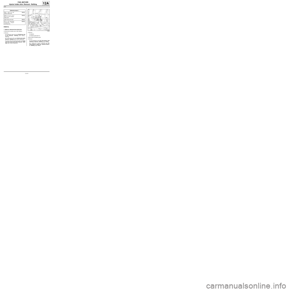
ting) (56A, Exterior equipment).aRemove:
-the dipstick,
-the dipstick guide bolts (1) .
aMove aside the dipstick guide.
aRemove:
-the inlet distributor (see 12A, Fuel mixture, Inlet
distributor: Removal - Refitting, page 12A-29) ,
-the « injector rail - injector » assembly (see 17B,
Petrol injection, Injector rail - Injectors: Remov-
al - Refitting, page 17B-27) . Tightening torquesm
bolts 1 and 2 on the
injector holder shim30 N.m
bolts 3, 4, 5, 6, 7, 8, 9
and 10 on the injector
holder shim25 N.m
upper timing cover bolt40 N.m
bolt on the right-hand
suspended engine
mounting cover62 N.m
132368
Page 311 of 652
12A-46
FUEL MIXTURE
Injector holder shim: Removal - Refitting
K4M
12A
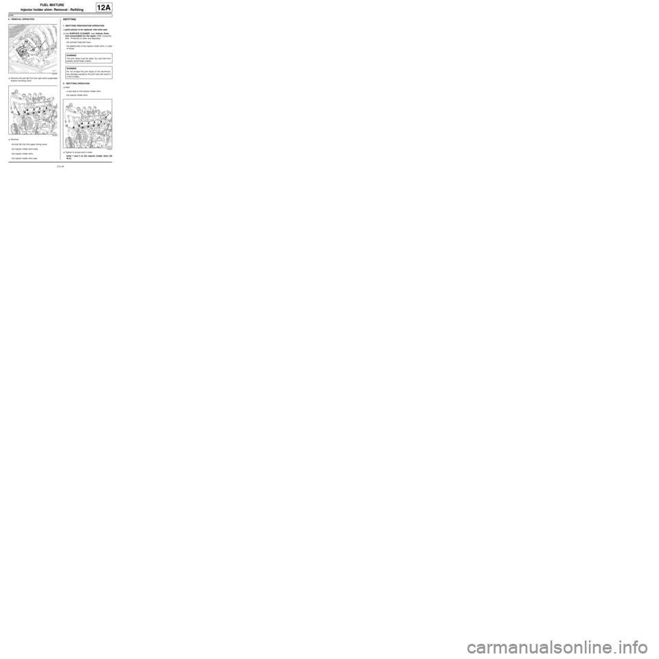
II - REMOVAL OPERATION
aRemove the bolt (2) from the right-hand suspended
engine mounting cover.
aRemove:
-the bolt (3) from the upper timing cover,
-the injector holder shim bolts,
-the injector holder shim,
-the injector holder shim seal.REFITTING
I - REFITTING PREPARATION OPERATION
aparts always to be replaced: Inlet shim seal.
aUse SURFACE CLEANER (see Vehicle: Parts
and consumables for the repair) (04B, Consuma-
bles - Products) to clean and degrease:
-the cylinder head joint face,
-the gasket face of the injector holder shim, in case
of reuse.
II - REFITTING OPERATION
aRefit:
-a new seal on the injector holder shim,
-the injector holder shim.
aTighten to torque and in order:
-bolts 1 and 2 on the injector holder shim (30
N.m),
131777
102303
WARNING
The joint faces must be clean, dr y and free from
grease (avoid finger marks).
WARNING
Do not scrape the joint faces of the aluminium,
any damage caused to the joint face will result in
a risk of leaks.
102303